Project 1
Project 1
Given below is a plan view of a framing layout of a typical school classroom. Design beam marked B1 and the floor slab per IS 456-2000. Use M25 concrete and Fe 415 steel. Use 20 mm clear cover for slab and 30 mm clear cover for beam. Consider a 2.5 kN/m2 super imposed dead load accounting for floor finish and ceiling.
Solution:
In the given framing layout, we first need to analyze the slab followed by the beam. The individual slab panels have length of 8 m and width of 3 m . Their aspect ratio is 8/3 = 2.67 which is greater than 2. Therefore, the slab will behave like a one way slab spanning between the horizontal beams.
Slabs are acting like 4 span continuous slab with 3m length of each span. Per cl 24.2 of IS 456-2000, for slabs spanning in one direction and continuous over supports shall be designed according to provisions applicable to continuous beams.
Let us start with estimating thickness of slab based on span/depth ratios per IS 456-2000.
Per 23.2.1 of IS 456-2000, span/effective depth for continuous member = 26
Let effective depth of slab required be d
3000/d = 26
d = 3000/26 = 115 mm
Considering clear cover of 20 mm and 8mm diameter longitudinal bars, let us provide 150 mm thick slab.
Super imposed dead load = 2.5 kN/m2
Self weight of slab = 0.15*25 = 3.75 kN/m2
Given floor is that of a classroom of a school. Per Table 1 of IS 875 part 2, live load to be used for classrooms of educational buildings is 3 kN/m2
Therefore, the slab is subjected to a total dead (fixed) load of 3.75+2.5 = 6.25 kN/m2
Live (not fixed) load = 3 kN/m2
Since the slab is spanning one way and provisions of continuous beam applies, let us use Bending moment coefficients of table 12 of IS 456-2000 to determine design moments of slab.
Given slab is 4 span continuous slab. Let us consider a 1000 mm (1 m) width strip of the slab.
Dead load on the strip = 6.25*1 = 6.25 kN/m
Live load on strip = 3*1 = 3 kN/m
Moment near middle of end span due to dead load = +(1/12)*6.25*32 = 4.7 kNm
Moment near middle of end span due to live load = +(1/10)*3*32 = 2.7 kNm
Ultimate moment near middle of end span per load combination 1.5D+1.5L = 1.5*(4.7 + 2.7)= 11.1 kNm
Moment at middle of interior span due to dead load = +(1/16)*6.25*32 = 3.52 kNm
Moment at middle of interior span due to live load = +(1/12)*3*32 = 2.25 kNm
Ultimate moment at middle of interior span per load combination 1.5D+1.5L = 1.5*(3.52 + 2.25)= 8.7 kNm
Moment at support next to end support due to dead load = -(1/10)*6.25*32 = -5.62 kNm
Moment at support next to end support due to live load = -(1/9)*3*32 -3 kNm
Ultimate moment at support next to end support per load combination 1.5D+1.5L = 1.5*(-5.62- 3)= -13 kNm
Moment at other interior support due to dead load = -(1/12)*6.25*32 = -4.69 kNm
Moment at other interior support due to live load = -(1/9)*3*32 -3 kNm
Ultimate moment at other interior support per load combination 1.5D+1.5L = 1.5*(-4.69- 3)= -11.6 kNm
The design moments for the slab is as shown below:
Let us determine the slab reinforcement based on moment demands
Effective depth of top and bottom slab reinforcement = d=150 – 20 – 8/2 = 126 mm
Bottom reinforcement required near middle of end span:
[(1.015*fy)/(100*fck)]*p2 – p + 100*Mu/(0.87*fy*b*d2)=0
fck = 25 MPa; fy = 415 MPa; Mu = 11.1*106 Nmm; b = 1000 mm; d = 126 mm
Substituting these values in above quadratic equation, we get
0.168*p2 – p + 0.194 = 0
p = 0.2
Area of steel required = (0.2/100)*1000*126=252 mm2
5 – 8 mm diameter bars within 1000 mm width.
Rebar spacing required = 1000/(5-1)=250 mm
Bottom reinforcement required at middle of interior span:
[(1.015*fy)/(100*fck)]*p2 – p + 100*Mu/(0.87*fy*b*d2)=0
fck = 25 MPa; fy = 415 MPa; Mu = 8.7*106 Nmm; b = 1000 mm; d = 126 mm
Substituting these values in above quadratic equation, we get
0.168*p2 – p + 0.152 = 0
p = 0.156
Area of steel required = (0.156/100)*1000*126=196.56 mm2
4 – 8 mm diameter bars within 1000 mm width.
Rebar spacing required = 1000/(4-1)=333.33 mm
Top reinforcement required at support next to interior support:
[(1.015*fy)/(100*fck)]*p2 – p + 100*Mu/(0.87*fy*b*d2)=0
fck = 25 MPa; fy = 415 MPa; Mu = 13*106 Nmm; b = 1000 mm; d = 126 mm
Substituting these values in above quadratic equation, we get
0.168*p2 – p + 0.227 = 0
p = 0.236
Area of steel required = (0.236/100)*1000*126=297.36 mm2
6 – 8 mm diameter bars within 1000 mm width.
Rebar spacing required = 1000/(6-1)=200 mm
Top reinforcement required at other interior support:
[(1.015*fy)/(100*fck)]*p2 – p + 100*Mu/(0.87*fy*b*d2)=0
fck = 25 MPa; fy = 415 MPa; Mu = 11.6*106 Nmm; b = 1000 mm; d = 126 mm
Substituting these values in above quadratic equation, we get
0.168*p2 – p + 0.202 = 0
p = 0.209
Area of steel required = (0.209/100)*1000*126=263.34 mm2
6 – 8 mm diameter bars within 1000 mm width.
Rebar spacing required = 1000/(6-1)=200 mm
Maximum allowable spacing of slab reinforcement = min(3*d, 300) = min(3*126,300)= 300 mm.
Also, provide 8mm@300mm spacing temperature and shrinkage reinforcement in the other direction.
The slab reinforcement is as shown below
After the slab has been designed, now we need to design the beam B1.
Typical span of beam = 8m = 8000 mm
Per span/effective depth = 26 for continuous beam, effective depth required = 8000/26=307.7 mm
Considering clear cover of 30 mm, 8mm stirrups and 16 mm longitudinal reinforcement, let us consider 450 mm deep beam.
Also, let us assume 250 mm wide beam
The beam is a typical interior beam supporting the one way slab.
Uniform dead load on beam from slab = dead load on slab*tributary width of beam = 6.25*3 = 18.75 kN/m
Uniform live load on beam from slab = live load on slab*tributary width of beam = 3*3 = 9 kN/m
Weight of portion of beam below the slab = 25*0.25*(0.45-0.15)= 1.87 kN/m
Total dead load on beam = 18.75 + 1.87 = 20.6 kN/m
Live load on beam = 9 kN/m
Given beam is three span continuous beam. Let us determine moment in beam based on table 12 coefficients.
Moment near middle of end span due to dead load = +(1/12)*20.6*82 = 109.9 kNm
Moment near middle of end span due to live load = +(1/10)*9*82 = 57.6 kNm
Ultimate moment near middle of end span per load combination 1.5D+1.5L = 1.5*(109.9 + 57.6)= 251.25 kNm
Moment at middle of interior span due to dead load = +(1/16)*20.6*82 = 82.4 kNm
Moment at middle of interior span due to live load = +(1/12)*9*82 = 48 kNm
Ultimate moment at middle of interior span per load combination 1.5D+1.5L = 1.5*(82.4 + 48)= 195.6 kNm
Moment at support next to end support due to dead load = -(1/10)*20.6*82 = -131.85 kNm
Moment at support next to end support due to live load = -(1/9)*9*82 -64 kNm
Ultimate moment at support next to end support per load combination 1.5D+1.5L = 1.5*(-131.85-64)= -294 kNm
Maximum moment = 294 kNm in the beam
Let us check adequacy of beam depth for the given moment to ensure under reinforced singly reinforced section
For Fe 415 steel, xu,max/d = 0.48
xu,max = 0.48*d
Compression force = 0.36*fck*xu,max*b = 0.36*fck*0.48*d*b = 0.1728*fck*b*d
Lever arm length = d-0.42*xu = d-(0.42*0.48*d)=0.8*d
Mu,lim = 0.1728*fck*b*d*0.8*d = 0.138*fck*b*d2
For the considered beam section,
fck = 25 MPa, b = 250 mm, d = 450-30-8-16/2=404 mm
Mu.lim = 0.138*25*250*4042 = 140.77 kNm
Moment demand in beam is 294 kNm. Therefore, the beam depth is not adequate to ensure under reinforced section which is singly reinforced.
Let effective depth required to ensure singly reinforced section be d
294*106 = 0.138*25*250*d2
d = 583.84 mm
Since the beam will end up being very deep , let us also consider widening the beam so that we end up with effective depth of around 500 mm.
Let us consider 350 mm wide beam.
294*10^6 = 0.138*25*350*d2
d = 493 mm
Let us consider 350 mm x 550 mm beam
We need to revise the total dead load on the beam since the beam has been upsized.
Weight of portion of beam below the slab = 25*0.35*(0.55-0.15)= 3.5 kN/m
Total dead load on beam = 18.75+ 3.5 = 22.25 kN/m
Moment near middle of end span due to dead load = +(1/12)*22.25*82 = 118.7 kNm
Moment near middle of end span due to live load = +(1/10)*9*82 = 57.6 kNm
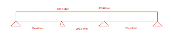
Ultimate moment near middle of end span per load combination 1.5D+1.5L = 1.5*(118.7 + 57.6)= 264.4 kNm
Moment at middle of interior span due to dead load = +(1/16)*22.25*82 = 89 kNm
Moment at middle of interior span due to live load = +(1/12)*9*82 = 48 kNm
Ultimate moment at middle of interior span per load combination 1.5D+1.5L = 1.5*(89 + 48)= 205.5 kNm
Moment at support next to end support due to dead load = -(1/10)*22.25*82 = -142.4 kNm
Moment at support next to end support due to live load = -(1/9)*9*82 -64 kNm
Ultimate moment at support next to end support per load combination 1.5D+1.5L = 1.5*(-142.4-64)= -309.6 kNm
Maximum moment = 309.6 kNm in the beam
Let us check adequacy of beam depth for the given moment to ensure under reinforced singly reinforced section
Mu,lim = 0.1728*fck*b*d*0.8*d = 0.138*fck*b*d2
For the considered beam section,
fck = 25 MPa, b = 350 mm, d = 550-30-8-16/2=504 mm
Mu.lim = 0.138*25*350*5042 = 306.7 kNm
Moment demand in beam is 309.6 kNm. Therefore, the beam depth is not adequate to ensure under reinforced section which is singly reinforced. This is also because of the fact that grade of concrete is M25. Let us propose to use higher grade of concrete (M30) instead of M25 since typically M30 concrete is used in beams
Mu.lim = 0.138*30*350*5042 = 368.1 kNm
Maximum moment is less than Mu,lim. Therefore, we can proceed with 350 mm x 550 mm beam with M30 concrete and Fe 415 steel
The design moments are as shown below
Bottom reinforcement required near middle of end span:
[(1.015*fy)/(100*fck)]*p2 – p + 100*Mu/(0.87*fy*b*d2)=0
fck = 30 MPa; fy = 415 MPa; Mu = 264.4*106 Nmm; b = 350 mm; d = 504 mm
Substituting these values in above quadratic equation, we get
0.140*p2 – p + 0.824 = 0
p = 0.95
Area of steel required = (0.95/100)*350*504=1675.8 mm2
9 - 16 mm diameter bars.
It is not possible to accommodate 9 bars within 350 mm width, let us consider 25mm diameter bars
Number of 25 mm diameter bars required = 3.4
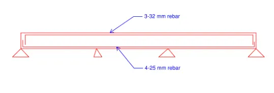
Provide 4-25 mm diameter bars
Bottom reinforcement required at middle of interior span:
[(1.015*fy)/(100*fck)]*p2 – p + 100*Mu/(0.87*fy*b*d2)=0
fck = 30 MPa; fy = 415 MPa; Mu = 205.5*106 Nmm; b = 350 mm; d = 504 mm
Substituting these values in above quadratic equation, we get
0.140*p2 – p + 0.64 = 0
p = 0.71
Area of steel required = (0.71/100)*350*504=1252.44 mm2
3 – 25 mm diameter bars
Top reinforcement required at support next to interior support:
[(1.015*fy)/(100*fck)]*p2 – p + 100*Mu/(0.87*fy*b*d2)=0
fck = 30 MPa; fy = 415 MPa; Mu =309.6*106 Nmm; b = 350 mm; d = 504 mm
Substituting these values in above quadratic equation, we get
0.140*p2 – p + 0.964 = 0
p = 1.15
Area of steel required = (1.15/100)*350*504=2028.6 mm2
5 – 25 mm diameter bars
Since it is very difficult to accommodate 5-25mm within 350 mm width due to clear spacing, let us provide 32 mm rebar.
Provide 3-32 mm bars at top
Therefore, the beam reinforcement is as shown below: