Project 1
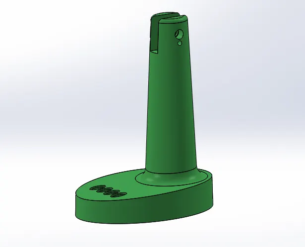
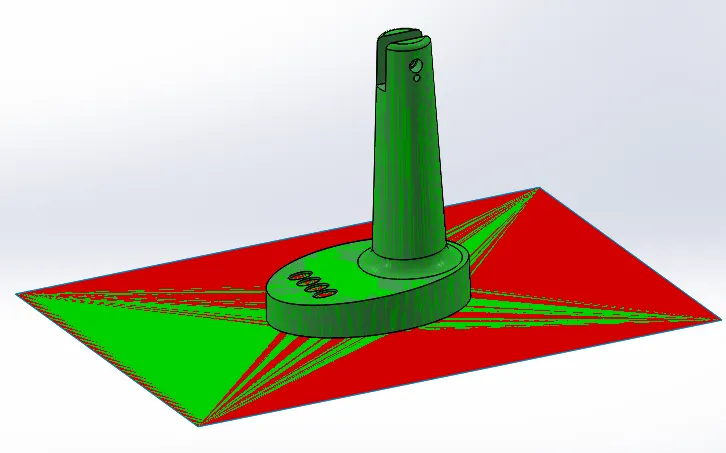
Step 1 - Draft Analysis - was done to select the tool direction and to check for an adequate draft is provided or not.
Step 2. Skrinkage - was given as per the ABS matrial = 0.6% i.e - 1.006
Step 3. Parting line - was drawn in such a way that the minimum number of sliders to make and matchining draft was provided.
Step 4. Shut-off surface - was made.
Step 5. Parting surface - was made using planar surface and then trim command is used to match the surface.
Step 6. Core and cavity surfaces - merging core and cavity surfaces with parting surfaces.
Step 7. Assembly - I started working in assembly where i created two new part file.
Step 8. Sprue alignment - sprue location was aligned in the center of the part.
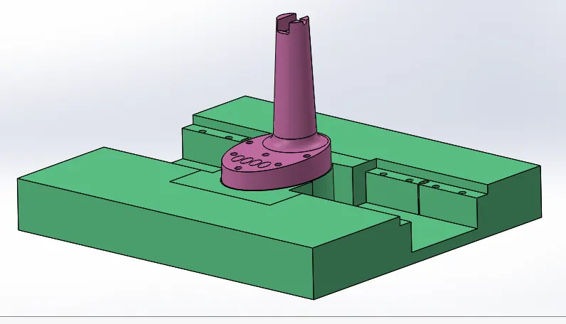
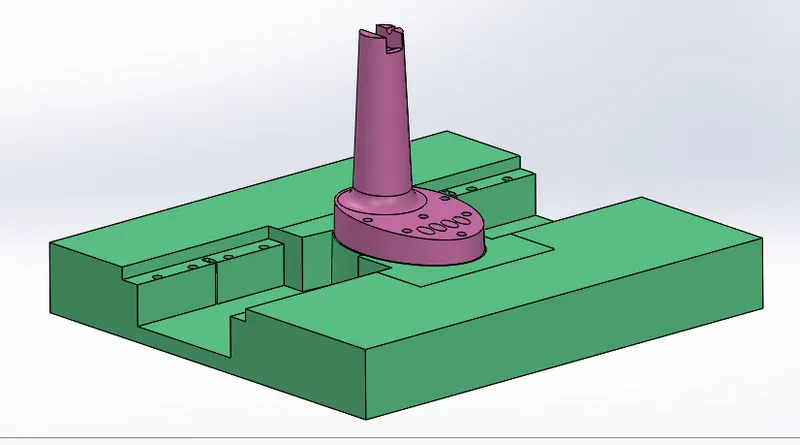
Step 9. Core block - Outer core block and inner core block was made as per the component and merged them.
Step 10 - Cavity block - as per the core block as procedure was followed to make the cavity block.
Step 11. Reliefs - added reliefs between the blocks wherever was necessary to avoid rubbing of the blocks.
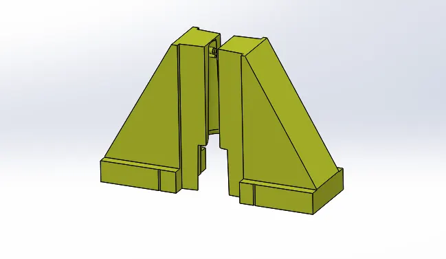
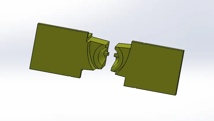
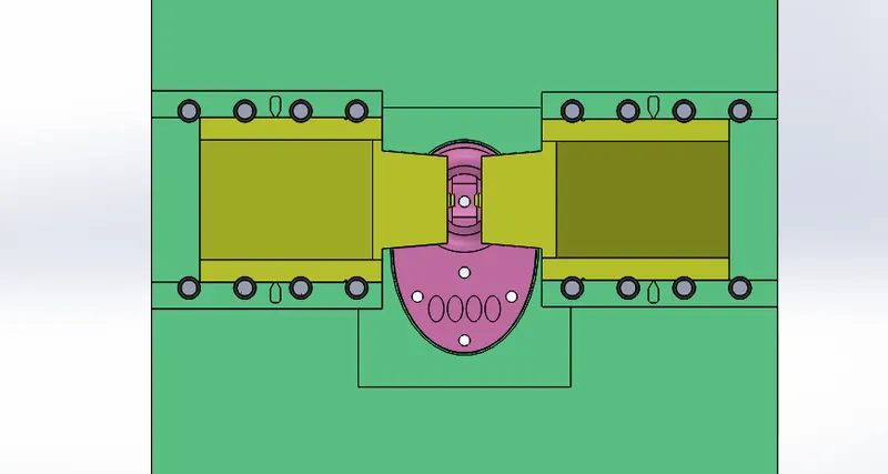
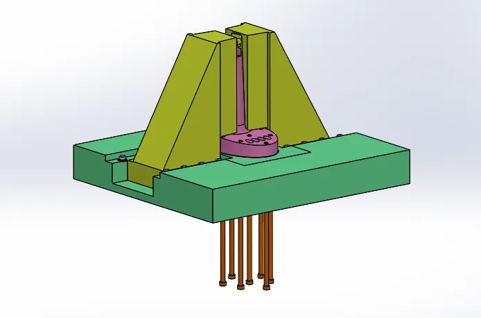
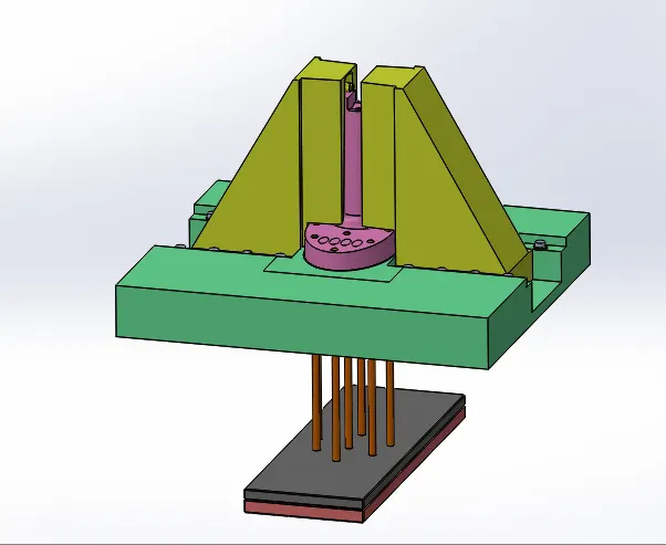
Step 12. Sliders - sliders was made as per the profile wherever is needed and mached according to the core and cavity block.
Step 13. Washers - washer was made for slider movement.
Step 14. Slider lock - was added as per calculation of movement to eject the part easily.
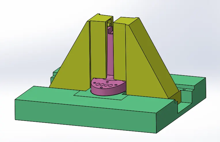
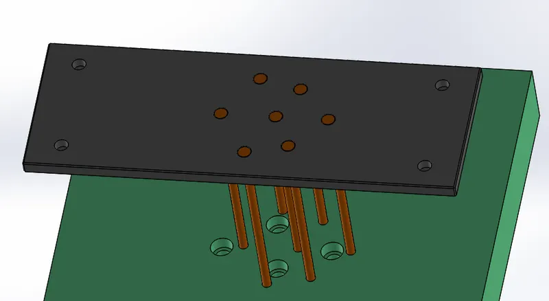
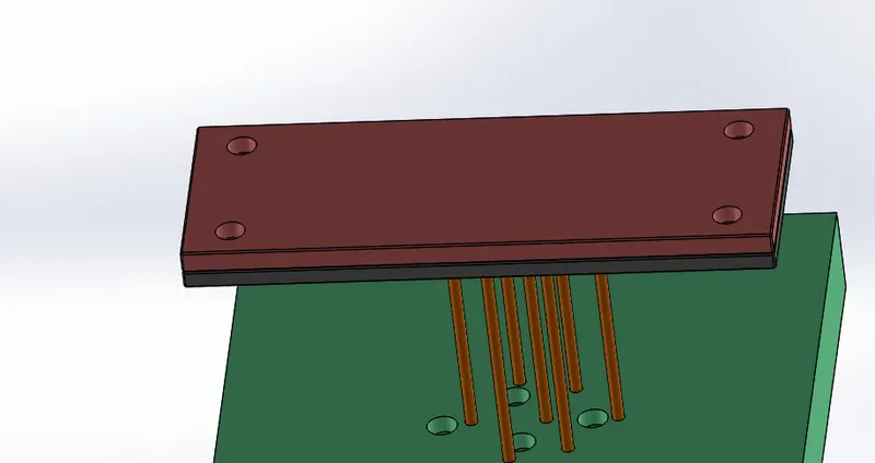
Step 15. Ejector pin - making ejector pin to eject the component and modifying core block as per pin.
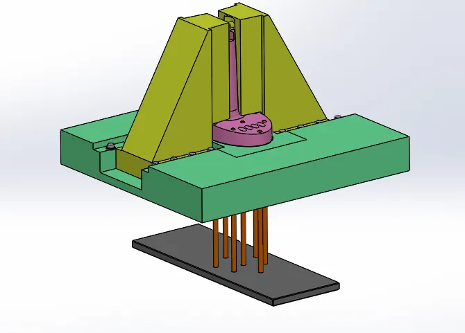
Step 16. Ejector plate - making ejector plate for the ejector pin movement.
Step 17. Ejector back plate - making ejector back plate for ejector plate fitting.
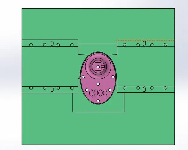
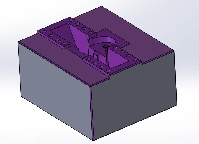
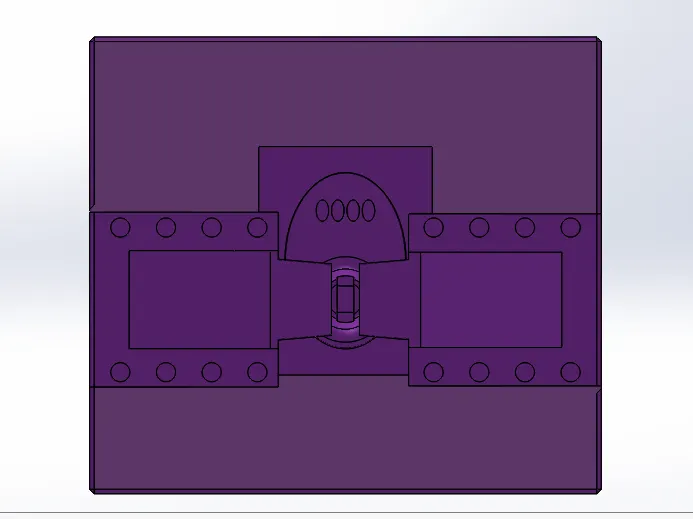
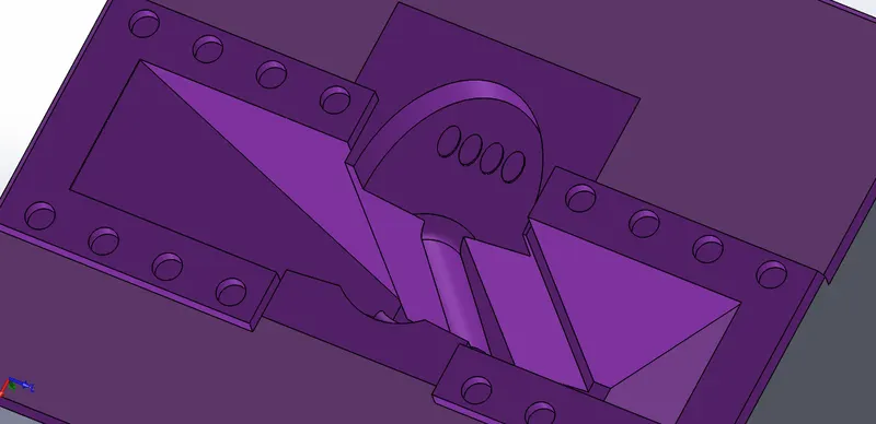
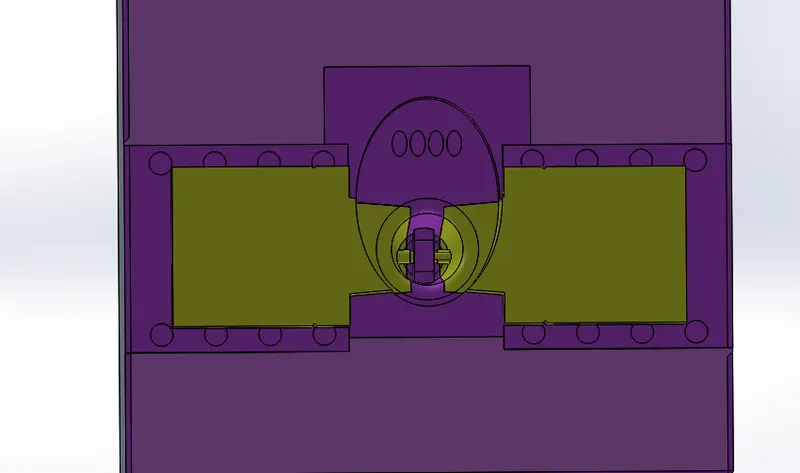
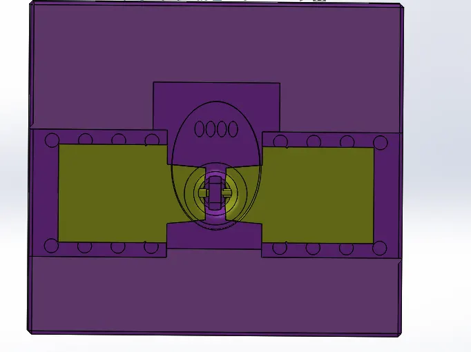
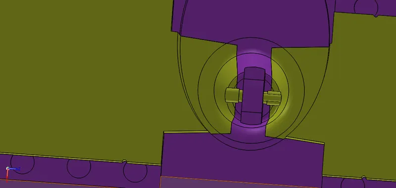
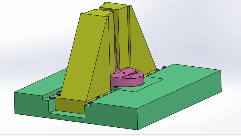
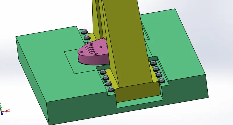
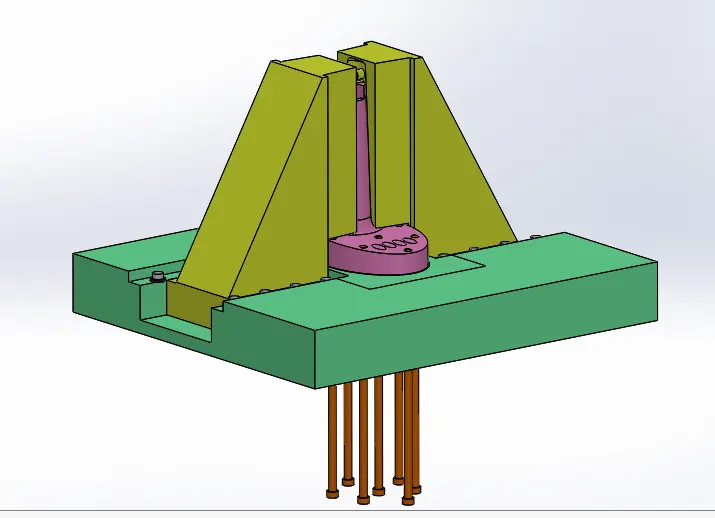
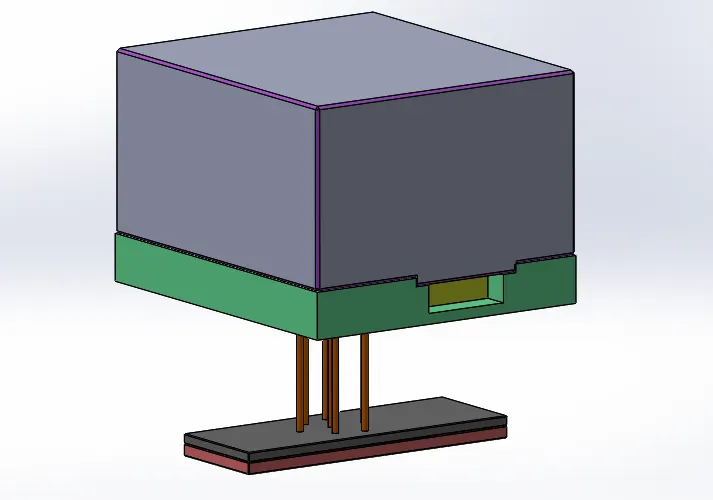
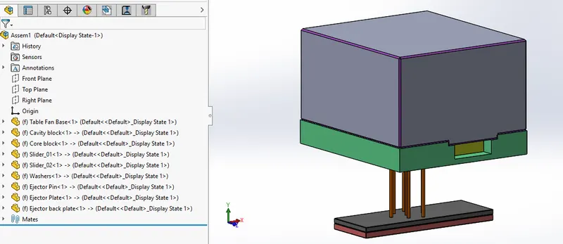
Here are the pictures of the mold created.