Project 1
Q1.
Aim :- To design the battery pack with the capacity 150Kw 120V by using 3500mAh 3.6V. And BMS topology for the battry pack
Calculation:- To design the battery pack we need cells which are connected in series and parallel to meet the requirment. The required condition - 220v and 50Ah.
Let us consider the cells with
Nominal voltage = 3.6v
Capacity = 3000mAh = 3Ah
To meet the requirment of 120v and 150Kw, we need to find the number of cells connected in series and parallel.
First convert the battery capacity 150Kw to Ah
Amper hour = Watt hour / Voltage
Amper hour = 150*1000 / 120 = 1,250 Ah
Series:-
Number of cells in series = required voltage / Nominal voltage of the cell
Number of cells in series = 120/3.6 = 33.33
We have to round off to lower value and higher value
Case-1) Number of cells in series = 33
Case-2) Number of cells in series = 34
Total volatge = nominal votage of cell * number of cells in series
The condition to choose the number of cells are
Nomial voltage of battery should not excide the Load volatge
Max Volatge of battery should be less than the Load Max Volatge
Min Volatge of battery should be greater than the Load min Voltage
We have to round off to lower value so that it will not excide the required value
There fore Number of cells in series = 33
Output total volatge will be 118.8V
The output voltage can be adjusted to 120v by a Buckboost converter to meet the requirment of 120v
Parallel:
Number of cells in parallel = required capacity / cell capacity
Number of cells in parallel = 1,250 / 3 = 416.6
We have to round off to lower value and higher value
Case-1) Round off to lower value = Number of cells in series = 416
Case-2) Round off to higher value Number of cells in series = 417
The output capacity = cell capacity * number of cells in parallel
We can round off to higher value = 417
The output capacity = each cell capacity * number of cells in parallel = 417*3 = 1,251Ah
The number of cells in Parallel = 417
The Output Capacity will be 1,251Ah
The Current can be limitted to requied value bu using current limitters.
Now the battery pack is made of 33S417P pack so that it can meet the required output of 120v,1250Ah or 120V 5Kw
As the number of cells in series and parallel are very high which makes manufacturing difficult. So, we need to divide it into sub battery packs and remake the connections to get the requried output
As the BMS Supports the max 18 cells in series so we need to divide the 33 sereis cells to 18 cells series sub battery pack which leads to 2 seres sub connections one with 18 and another with 15
To make it compact parallel connectons we need to make 52 cells in parallel for each sub pack which leads to 8 parallel connections
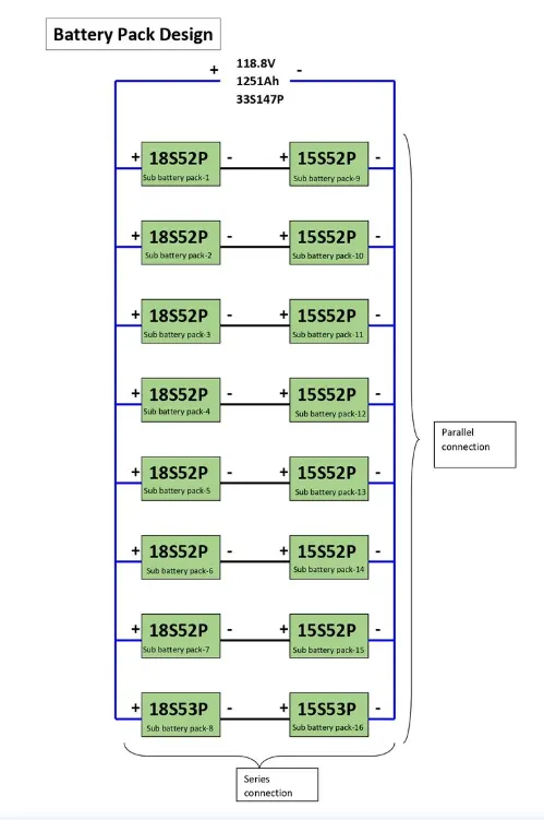
Total result in 2 sub battery packs in sereis one with 18 cells in series and another with 15 cells in series and 8 sub battery pack in parallel each with 52 cells in parallel and any one with 53 to meet the requirment 33S417P.
One sub battery pack configuration is 18S52P and another sub battery pack configuration is 15S52P which results in 33S52P pack with 8 copies. these 8 33S52P are connected in parallel (One of the pack with 33S53P) to make 33S417P.
Basic connections block diagram:
Back line indicates the series connection
Blue Line indicates the Parallel connection
Each 18S52P pack is connected in series with the each 15S52P pack results in 33S52P
All 8 33S52P(18S52P+15S52P) are connected in parallel results in 33S417P
Note that last pack in parallel connection contains as 18S35P series with 15S53P pack, one parallel connection is increased in that sub pack to meet the Requirement of 33S147P.
Battery Management Sytem (BMS):
BMS Topologi used in this battery pack is Master and Slave BMS Topologi. Because the total battery pack is made of sub battery packs so controlling and manufacturing will be easy.
Master and Slave BMS which has number of slave controllers are 16 and a Master controller which can handel 16 slaves.
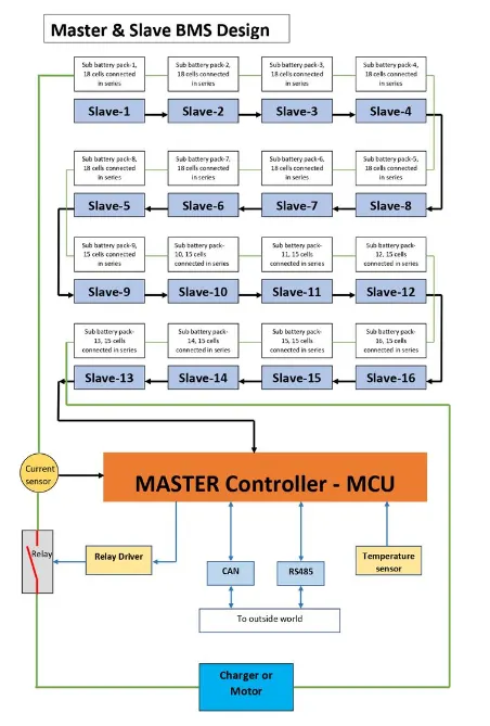
It consisting of input sensors of volatge,current and temperature. The voltage sensor analog signal is converted to digital signal by AFE, the current sennsor analog signal is converted to digital signal by the MCU or we can connect the ADC converter between the Current sensor and MCU, the temperature sensor analog signal is converted to digital signal by the MCU or we can connect the ADC converter between the Temperature sensor and MCU. The Realy module control the Realy which make or brack the circuit by the command given be the MCU. The CAN and RS485 are Communication protocalls to the Outside world.
The Blocks inside the red line are the BMS blocks. It isdesigned with the three 18 cell Slave controller which is AFE, it converts the anolog signal from voltage sensor in the battery to Digital signal. The 3 Slaves are connectes in seres as shown, the salve-1 will collect the data feom module-1 and send to slave-2, slave -2 will collect the data from module-2 , now the salve -2 consisting the data of slave-1 and 2 and it sends the both the data to slave-3, the save-3 will collect the data from module-3, now the slave-3 consisting the data of slave-1,2 and 3, like continues for all 16 slaves and at last all the data is send to Master controller which is MCU. It control the battery pack according to the protocals which is given to MCU.
Note that all the slave have a capacity of 18 cell series connection even though half of the sub battery packs have only 15 series cell besuse if we want to upgrade the capacity we can do by increasing Ah of battery pack i.e., by incresing the number of series cells. It makes easy to upgrade the battery pack but in a limitted way.
We can also use the combination of 8 Master and slave BMS i.e., 2 slaves 18S52Pa and 15S52P and a master controller of 8 numbers. For all master control will have one single controller or all the 8 master controllers can directly connected to the MCU. But its costly and complicated process.
Conclusion:
The battery pack was made to design as 33S147P divided into sub battery packs which is combination of 18S52P series with 15S52P, this combination is paralled with 8 copies as shown above toatl results in 33S147P with capacity of 150Kw with 120V.
To charge and discharge the Total battery pack Master and Slave BMS topology is used which is efficient in all ways like cost, design,control and instalation.
***************************************************************************************************
Q.2
3S2P Battery Pack configuration with generic battery block using Matlab/Simulink.
Total No of Cell in Battery Pack = No Cell in series * No cell in parallel
No Cell in Battery Pack = 3*2= 6
Step 1 Arrangement of 6 Cell
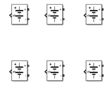
Figure 1 Arrangement of 6Cells
Step :2 Parallel Connection
The Figure 2 shows the batteries connected in parallel. For Parallel connection, batteries are connected from terminals to same terminals of other batteries that is positive terminal (+) of one battery is connected with positive (+) terminal of other battery and negative terminal (-) of one battery with negative terminal (-) of other battery.
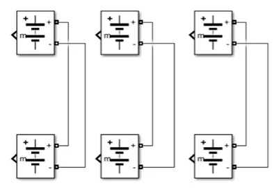
Figure 2: Battery connected in parallel connection
Step 3 Series Connection
The Figure 3 shows the battery connected in seris and parallel combination. Batteries are connected form terminal to terminal in a way that the positive (+) terminal of one battery is connected with negative (-) terminal of the other battery and negative terminal (-) of one battery is connected with the positive terminal (+) of the other battery.
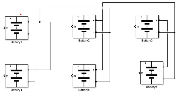
Figure 3 Battery connected in series and Parallel
Model Explantion:-
The figure 4 shows the 3S2P Battery pack simulink Model The voltage measurement block is connected across the battery pack to measure the battery pack voltage. The scope output used for the battry pack consists of SOC ( State of charge) , Current and voltage. The controlled current signal is given as the load to the battery pack. the constant block is determined eith battery capacity and it is given to the controlled curreent block.
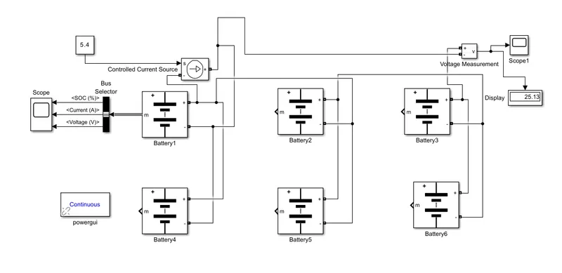
The Parameter Given inside the battery Given Below,
1. Nominal Voltage Cell 7.2V
2. Rated Capcity of cell 5.7Ah.
3. Maximum voltage of cell 8.3 v
Nominal Voltage of battery pack = No Cell in series *Nominal voltage of cell
Nominal Voltage of battery pack = 3* 7.2= 21.6V
Rated Capacity Battery Pack = No cell in parallel * Rated capacity of Cell
Rated Capacity Battery Pack = 2* 5.4 =10.8 Ah
The Model is For an 21.6 v and 10.8 Ah Battery.
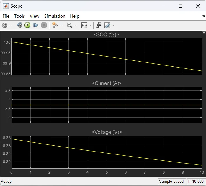
The Figure 5 shows the single battery output SOC, Voltage and current.
Plot 1: The SOC ( State Of Charge) is Started to reduce from 100% to 50% corresponding to the load given.
plot 2 : The current signal is determined by the load and the decrease in current is due to regenrative braking.
Plot 3: The voltage is around 8.3V. The increasing and decreasing voltage is with respect to the regenerative braking.
Overall Battery pack Voltage is =Maximum Voltage of battery * No cell in series
voltage =8.38*3= 25.13V
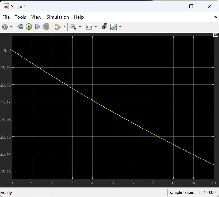
Over All battery pack Volatage
****************************************************************************************************