Project 1
project-1
Buck Converter with continuous inductor current(Asynchronous)
Design Specifications:
Vin =40v-50v
Vout =30v
p=500w
Iout=16.67A
Ro=1.76ohm
let consider
inductor ripple current is 20%, ripple voltage across the capacitor is 1%, switching frequency is(Fs) 1MHz.
The duty cycle Range D= 0.9-0.75
Inductor Value L0 =3.529`micro`(found it from the formula)`
Capacitor Value C0 =42.50 `micro`(found it from the formula)`
inductor average current IL=15.5A-17A
Inductor selection:
The selected inductor should withstand 1.5times of the inductor average current is 26A, Internal resistance should be very small.
the selected inductor model is VER2923-332
Capacitor selection
A real capacitor can be modeled as an equivalent series resistance(ESR)
`delta*ESR=delta IL*ESR
ESR =0.0882Ohm.
Compensator Selection:
Frequency of double pole(FLC)=13K HZ
Frequency of Zero(F ESR)=42.47K Hz
Zero crossover frequency(F0)= Fs/10=100k Hz
FLC <FESR<F0<(FS/2)
From the above condition, we conclude that type 2 compensator is suitable for the buck converter
For the desired location of poles and zeros:
Fz1=0.75*FLC=9.75K Hz.
Fp2= Fs/2=500k Hz.
calculation of capacitors and resistors values of type 2 compensator.
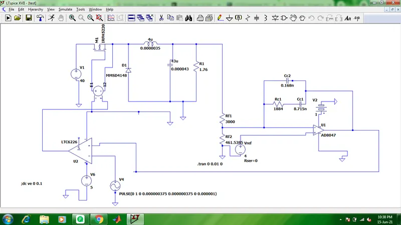
Let consider rf1=3000 ohm,
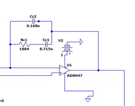
rc1=1.884k ohm, cc1=8.715n farad, cc2=0.168n farad, rf2=461.5385 ohm.
cross over frequency, phase margin of the loop gain transfer function of the closed-loop system.
4.309e-09 s^2 + 0.001413 s + 70.4
-----------------------------------------------------------
2.295e-21 s^4 + 7.289e-15 s^3 + 2.778e-10 s^2 + 4.575e-05 s
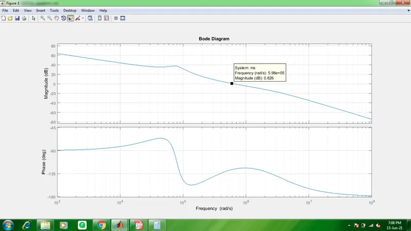
from bode plot phase margin is 53.79, switching frequency cross over frequency is 96k Hz
Voltage sensor: From the Voltage divider circuit sensing the output voltage and it is (Vref)4V.

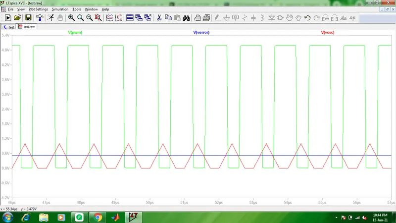
PWM Generator:
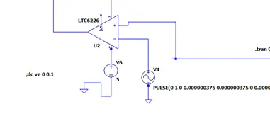
Using LTC6226 Op-Amp generating PWM pulses to Mosfet.
Type -2 Compensator:
Schematic diagram of Simulation Circuit:
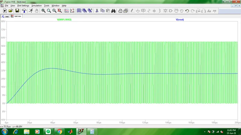
Wave forms of pwm and output voltage:
Vout Voltage and voltage across MOSFET: