Project 1
1. Design a multi-storey Residential Building located in Bangalore using STAAD Pro Connect Edition. The specification must be as follows:
|
Building floors |
G + 6 + R |
|
Plan dimension |
B = 25m , L = 16m |
|
Storey Height |
h = 3.5m |
|
Soil |
Hard soil |
|
Use |
Residential Purpose |
|
Safe Bearing Capacity |
180 kN/m2 |
|
Maximum slab thickness |
150mm |
Assume suitable sections for structural elements. Follow IS456, IS1893 and IS 875
Aim :
To design a multi story residential building located in Bangalore using STAAD pro connect edition
Procedure :
- Generation of nodes
- Adding beams and columns
- Defining and assigning materails ans material properties to struture
- Assigning supports
- Application of loads
- Analysis
Generation of nodes :
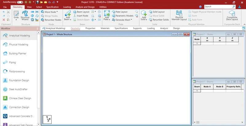
- Initially a new project is created with metric units and is saved in the appropriate location.
- The nodes are generated based on the dimensions of the building
- The dimensions are B=25m, L=16m and H=3.5m
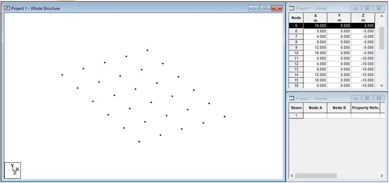
- The nodes are added starting from origin
- The first plane of nodes are added in positive X and negative Z directions with the spacing of 4m in X-axis and 5m in Y-axis
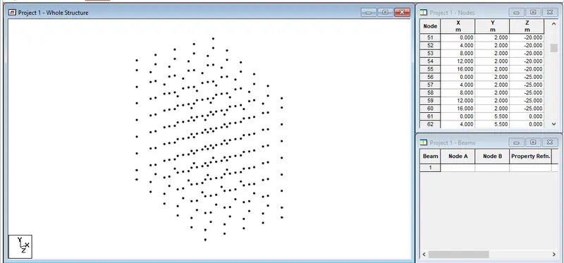
- Later all these nodes are copied and pasted to 6 floors starting from ground floor to 6 th floor with a height of 3.5m in Y direction
- Later, a roof has been added at the height of 2m from 6th floor.
Adding Beams and columns :
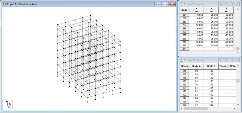
- Beams and columns are added initaially to the structure using the add beam option from geometry tab
- After adding all the beams and columns the materail and specifications are to be defined and assigned to these beams and columns
Assigining Materials and defining properties to the structure :
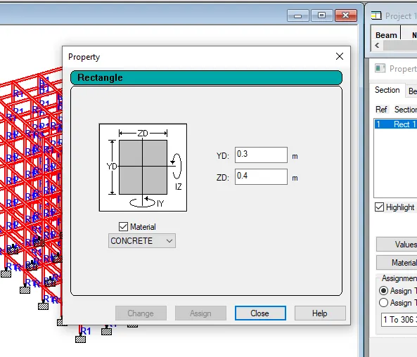
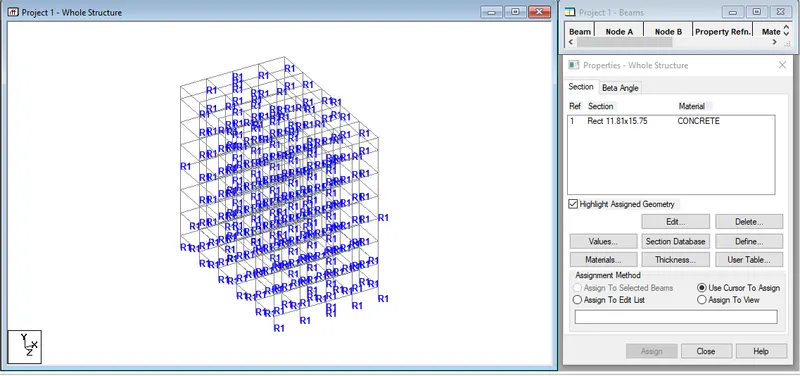
- Go to properties tab and cliclk on define to define a new crosssection
- In this case a rectangular section of 300mmX400mm is created
- This defined concrete crosssection is assigned to all the beams and columns using assign to view option.
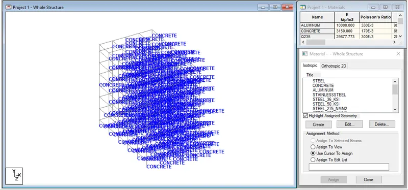
- Later, go to materails tab and assign conc rete to whole view using assign to view option.
Assigning supports:
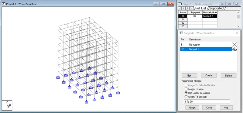
- A fixed support is defines using the define option in supports tab
- All the base nodes are selected and a fixed support is assigned to all these nodes
- Assign to selcted nodes option is used here to assign the fixed support to all base nodes.
Assigning of loads:
The various loadsacting on a structure are
- Self weight
- Floor load
- wind load
- load combinations
Self weight :
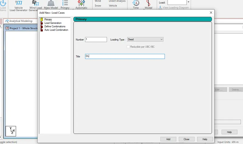
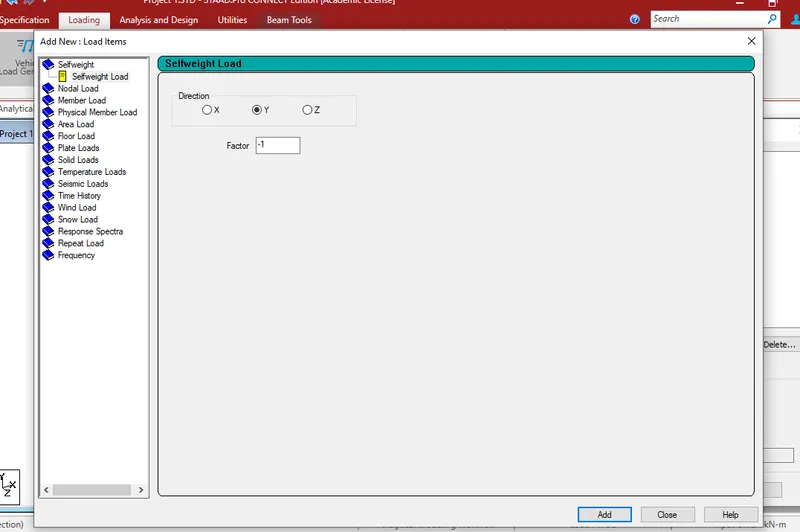
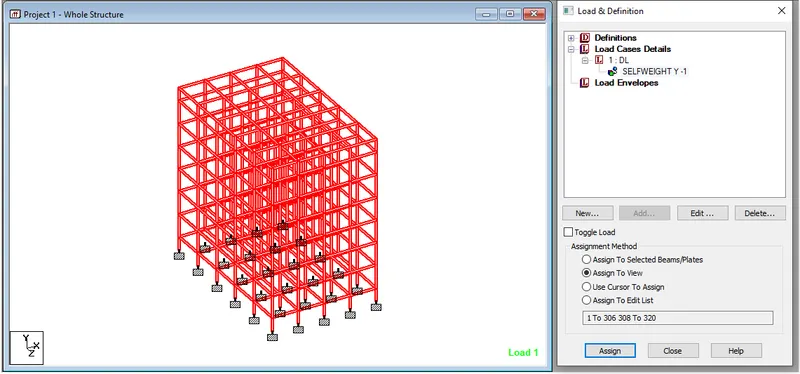
The self weight of the structure is calculate dby STAAD pro with self weight command in load case column. A self weight factor is added from the dead load case and is assigned to all the members.
Material specifications :
Assuming the size of beams = 300mmX400mm
Assuming size of columns = 300mX400mm
Assuming thickness of slab as 150mm
Load calculations:
(1) Dead loads:
(a) Dead load on floor :
- Dead weight due to slab = 0.15 x 25 = 3.75kN/sqm
- Partitions = 1.5kN/sqm
- Floor finish = 2.5kN/sqm
- Miscellaneous = 1kN/sqm
- Total floor load = 8.75kN/sqm
(b) Dead load on roof:
- Dead load on roof slab = 3.75kN/sqm
- Insulation and water proofing = 0.5kN/sqm
- MEP services = 0.5kN/sqm
- Miscellaneous = 0.5kN/sqm
- Total roof load = 5.25kN/sqm
(2) Live load :
(a) For residential bilding live load for a floor is 3kN/sqm
(b) For roof the live load is 1.5kN/sqm
(c) Wind load calculation as per IS875 part-111
Design wind spedd
we know that
Vz=Vbxk1xk2xk3xk4
Where,
Vb is basic wind speed (m/s)
k1 is reisk coefficent (IS 875 part-111 Table -1)
k2 is terrain roughness and height factor
k3 is topograhpy factor (IS 875 part-111 Clause 6.3.3)
k4 is importance factor for cyclic region
Vb = 33m/s ,for Bangalore (as per IS875 part-111)
k1 = 1
k2 = 1.15 (for height of 23m)
k3 = 1
k4 = 1
therefore , Vb = 33x1x1.15x1x1
Vb = 37.95m/s
Wind pressure (Pz) :
Pz = 0.6x (Vz)^2
Pz = 0.6 x (3.795)^2
Pz = 864.121N
Pz = 0.864kN
Similarly, we can calculate the wind pressure for different heights like below
| Height (m) | k1 | k2 | k3 | k4 | Vz | Pz | Pz in kN |
| 3.5 | 1 | 1.05 | 1 | 1 | 34.65 | 720.37 | 0.72 |
| 7 | 1 | 1.05 | 1 | 1 | 34.65 | 720.37 | 0.72 |
| 10.5 | 1 | 1.06 | 1 | 1 | 35.2 | 743.42 | 0.74 |
| 14 | 1 | 1.08 | 1 | 1 | 35.64 | 762.12 | 0.76 |
| 17.5 | 1 | 1.1 | 1 | 1 | 36.3 | 790.61 | 0.79 |
| 21 | 1 | 1.125 | 1 | 1 | 37.13 | 827.18 | 0.83 |
| 24.5 | 1 | 1.13 | 1 | 1 | 37.29 | 834.32 | 0.83 |
(d) Seismic load :
Design base shear :
Vb =Ah x W
where,
Ah = Horizontal coefficient of accelaration
W = seismic weight
As we know that Ah can be calculated by formula
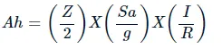
so, as the given location is bangalore
Seismic zone(Z) = Zone ii
Soil type(Sa) = Hard soil
Importance factor = 1 for residential building
Response reduction factor = 5
Calculation of Sa/g (design accelaration co-efficient for different soil types :

where,
h = height of the building
d = base dimension of the building at the plinth level along the consideration direction of earthquake shaking in m
Along X direction
Tx =0.09x23/4
T = 0.52 s
Along Z direction
Tz = 0.09x23/5
T = 0.41 s
Considerting the maximum time period, T = 0.52 s.
According to the IS code for hard soil whose T valueis between 0.4s to 4s , the value for Sa/g = 1.47
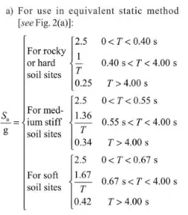
Sa/g = 1/T = 1.47
For reduction factor (R)
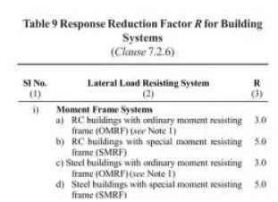
R = 5
I is importance factor, I = 1
Now, Ah = (0.1/2) x 1.47 x (1/5)
Ah = 0.0147
Seismic weight of building :
- Dead and live load calculations for all floors
area of each floor = 16x25 = 400sqm
- Typical floor weight due to dead load
DL = 8.75KN/sqm
so total dead load for each floor = 8.75 x 400 = 3500kn
DL due to roof = 5.25 x 400 = 2100kN
- Due to live load
floor load LL = 3kN/sqm, which is reduced by 50% due to addition of seismic load
LL = 1.5kN/sqm
Total LL for all the floors = 1.5 x 400 = 600kN
LL for roof is neglected according to IS code
- Total seismic weight W = Dl + LL + DL of roof
(3500+600)x6 + 2100 = 26766kN
Design base shear :
Ah = 0.0147
W = 26766kN
Design base shear Vb = 0.0147x26766
Vb = 393.46 kN
lateral force at different levels :
Formula according to IS code
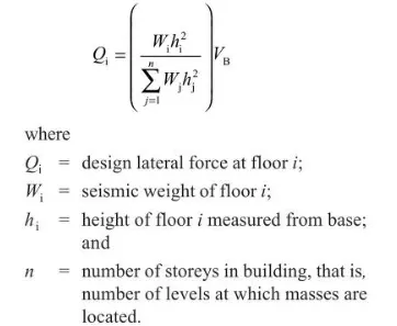
| storey level | wi | hi | wihi2 | ki | Lateral force(Qx) | Lateral force (Qz) |
| Roof | 2100 | 23 | 1110900 | 0.19 | 74.76 | 74.76 |
| fifth floor | 4100 | 21 | 1808100 | 0.31 | 121.98 | 121.98 |
| fourth floor | 4100 | 17.5 | 1255625 | 0.22 | 86.56 | 86.56 |
| third floor | 4100 | 14 | 803600 | 0.14 | 55.08 | 55.08 |
| second floor | 4100 | 10.5 | 452025 | 0.07 | 27.55 | 27.55 |
| first floor | 4100 | 7 | 323900 | 0.06 | 23.61 | 23.61 |
| ground floor | 4100 | 3.5 | 50225 | 0.009 | 3.54 | 3.54 |
| 5804375 | 393.46 | 393.46 |
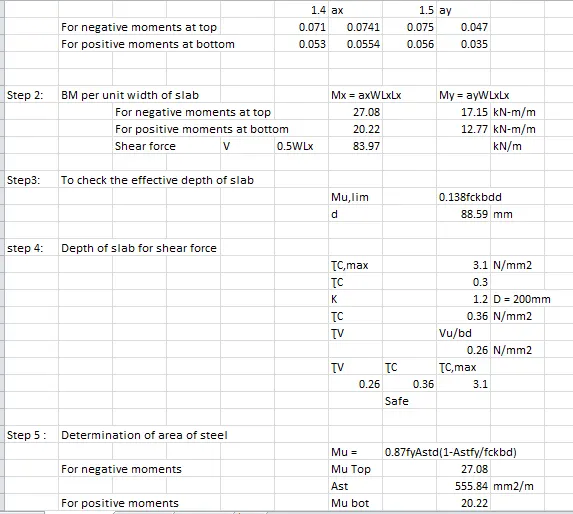
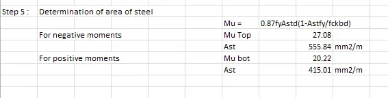
Design of slab element using MS-excel
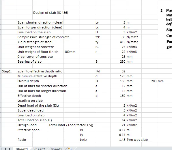
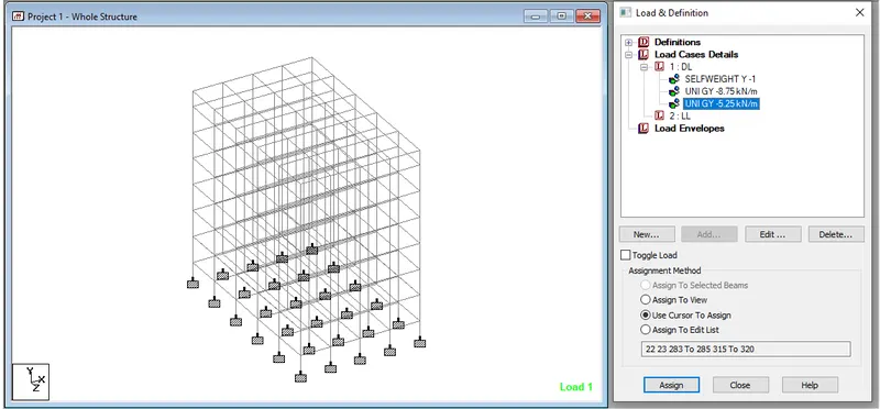
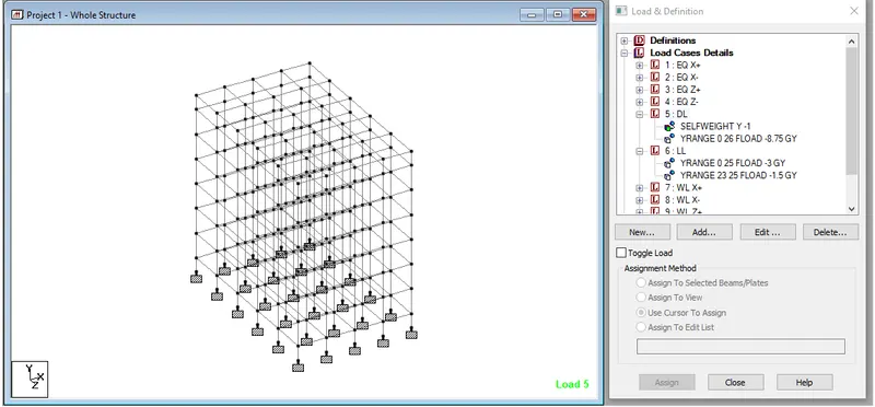
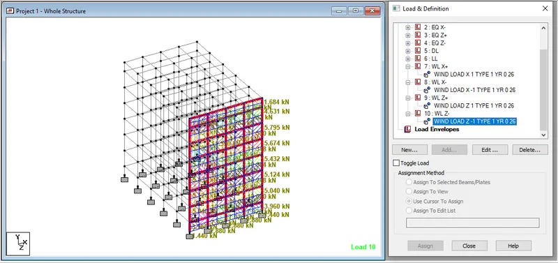
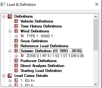
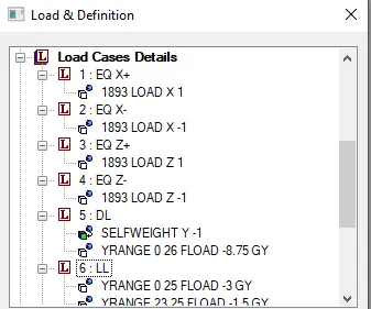
After calculating all the loads , the finaldead loads added to the structure are

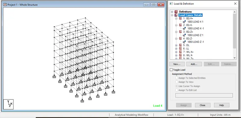
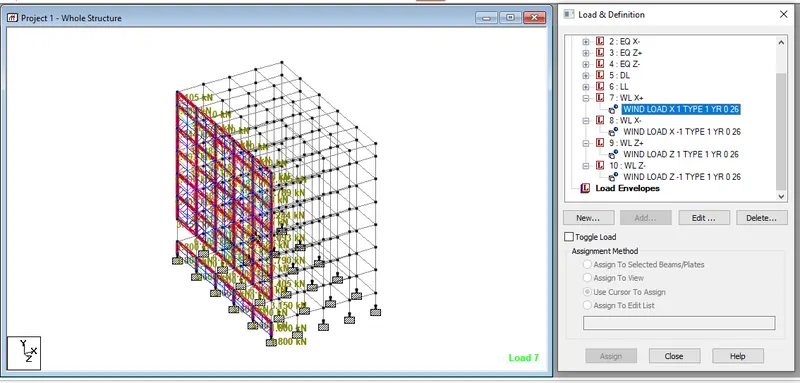
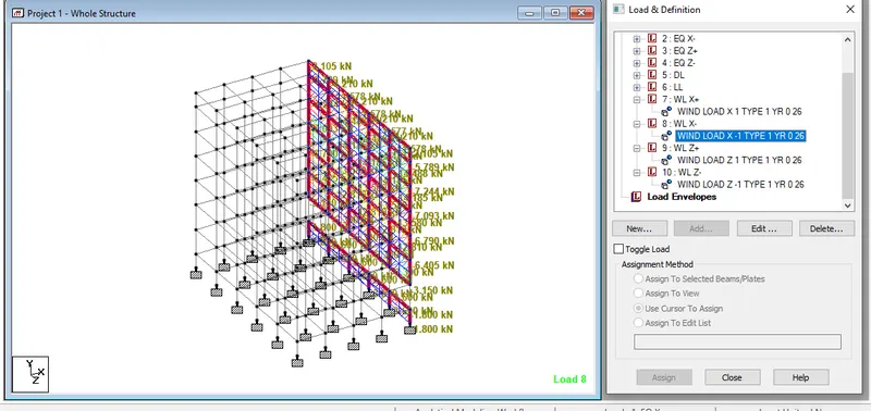
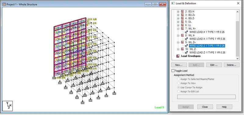
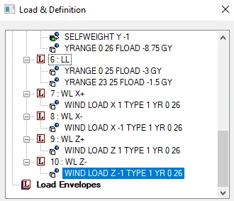
After adding and assigning all the live loads including seismic and wind loads
Lter, all the loads are rearranged into the order as below (As the seiesmic loads are to be added as the first loading cases)
- Seismic loads
- Dead load
- Live load
- Wind load
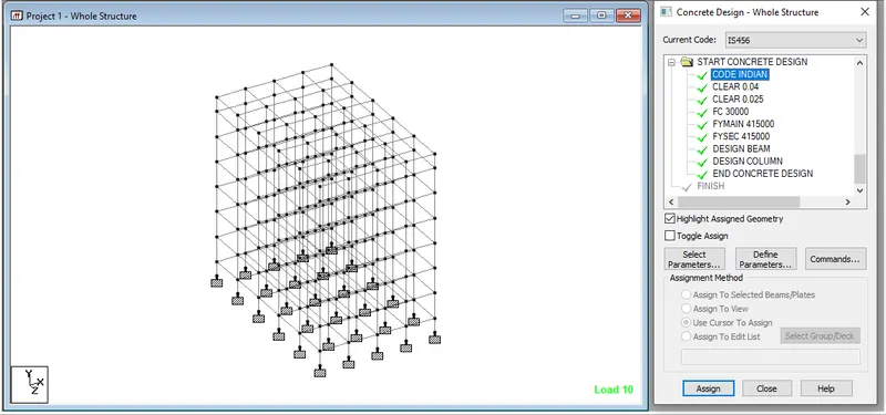
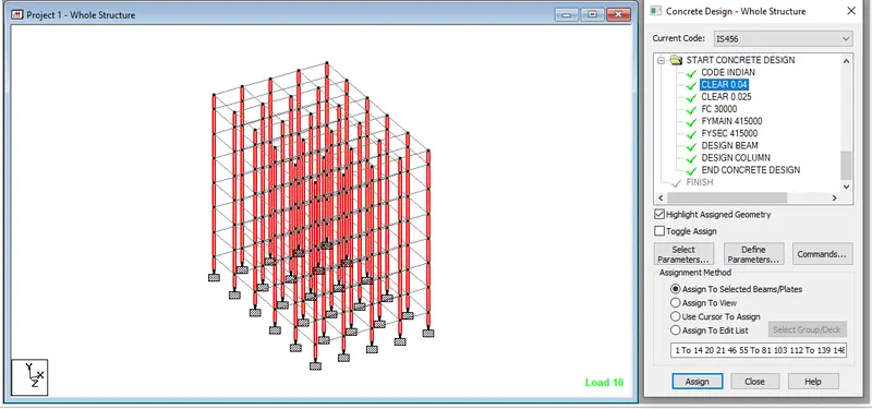
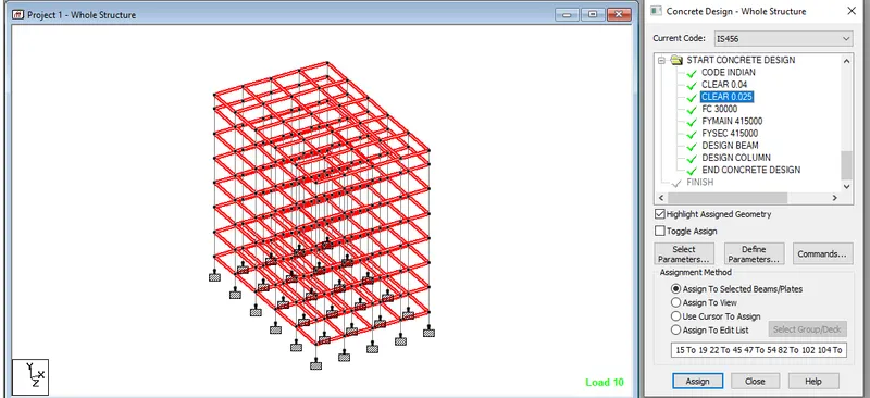
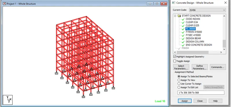
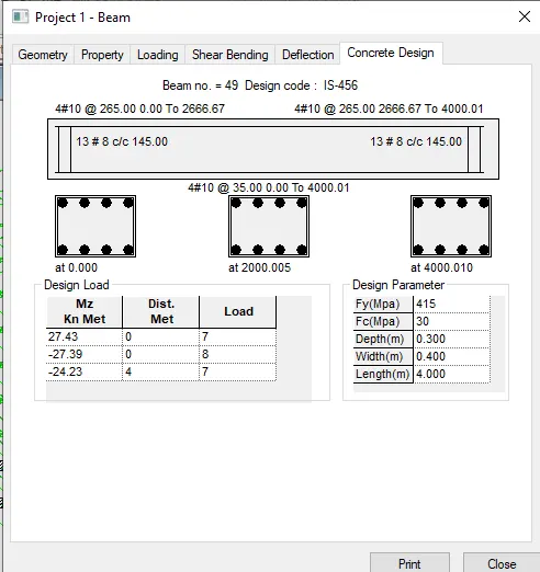
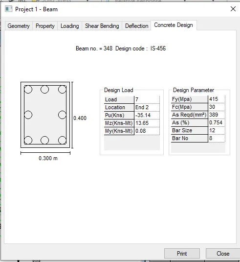
Design of structural elements from STAAD pro
Input and assigining of parameters
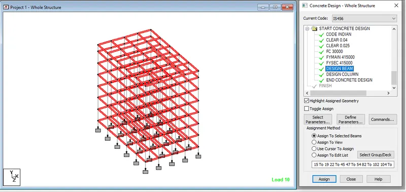
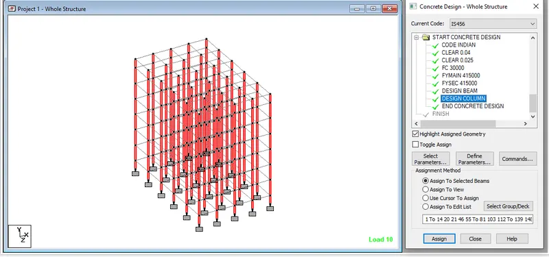
Design of beam from STAAD pro
Design of column from STAAD pro
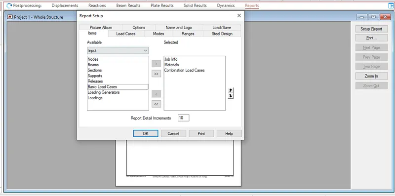
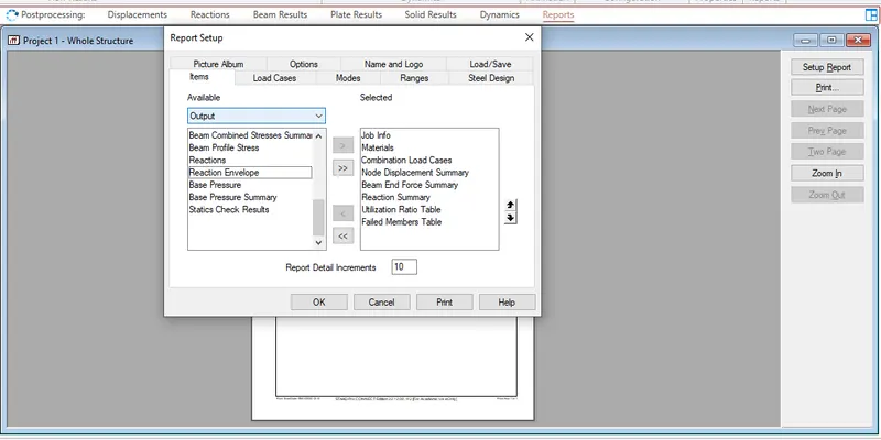
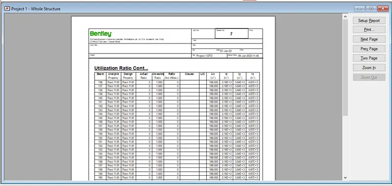
Design basis report(DBR) from STAAD pro
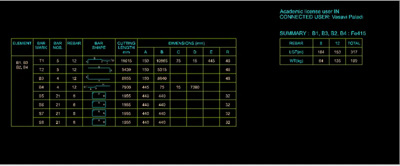
Bar bending schedule for beams
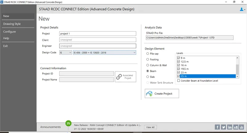
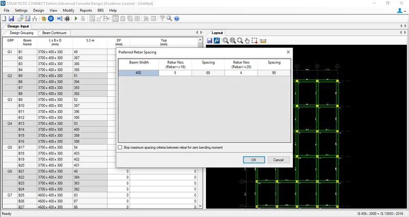
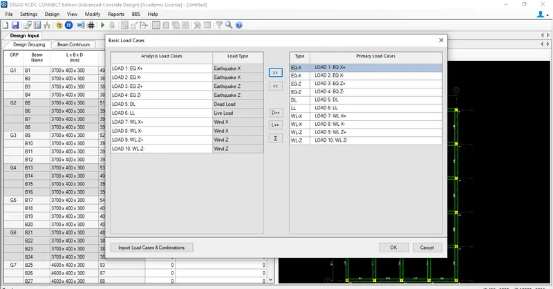
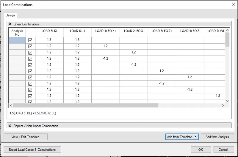
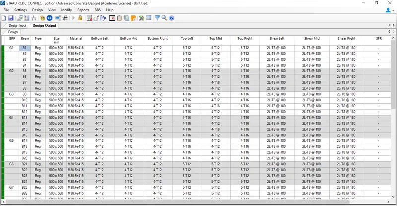
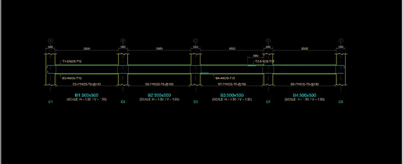
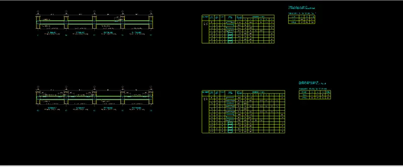
- A step by step procedure for Beam design in RCDC has been shown with the help of pictures below
- After analysing the structure, goto advanced concrete design which is present at the left side under workflow tab
- Select RCDC and selecr beams for a level
- Click on create project after giving it a name
- Now, RCDC takes all the required information from STAAD pro
- Noe, goto settings and give all the required settings such as grade of steel and concreet, clear cover etc
- Now, goto design tab and click on design
- A detailed design of beams can be seen and all the failed beams are shown with a red mark
- Calculations and others can be extracted from Reports tab
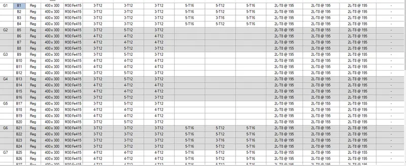
- Bar bending schedule can be extracted from BBS tab
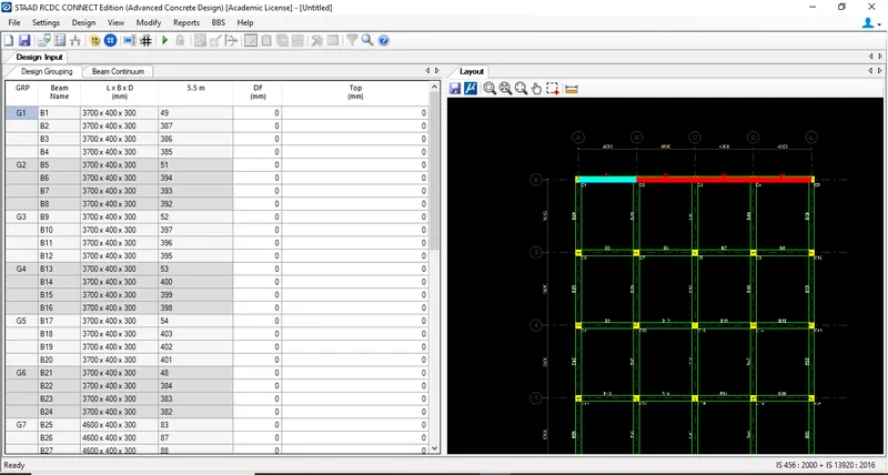
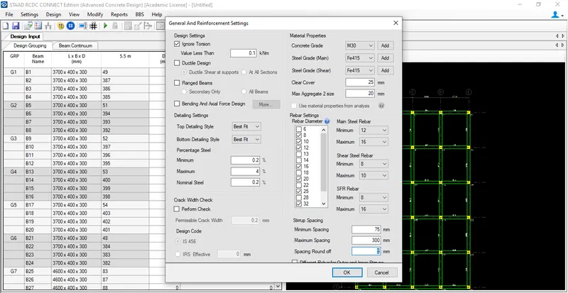
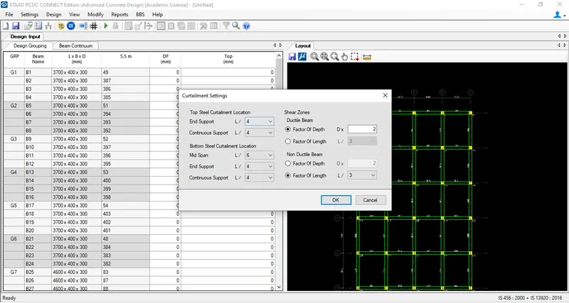
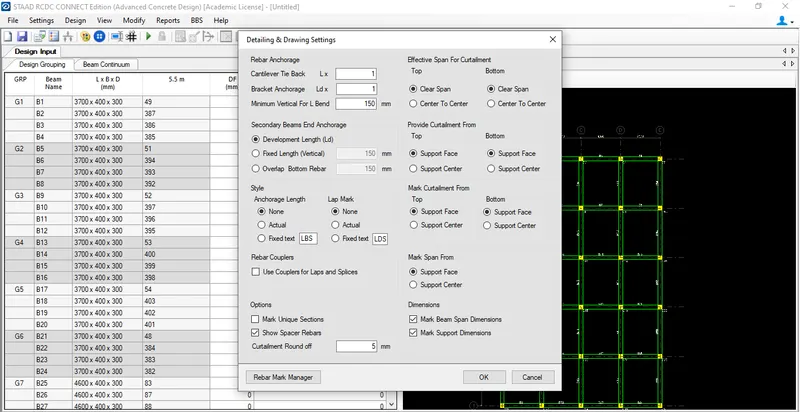
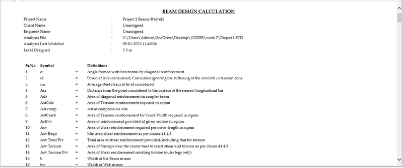
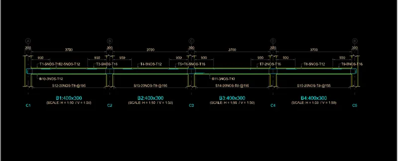
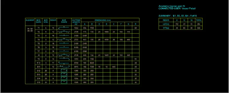
- There were some failed beams in the structure
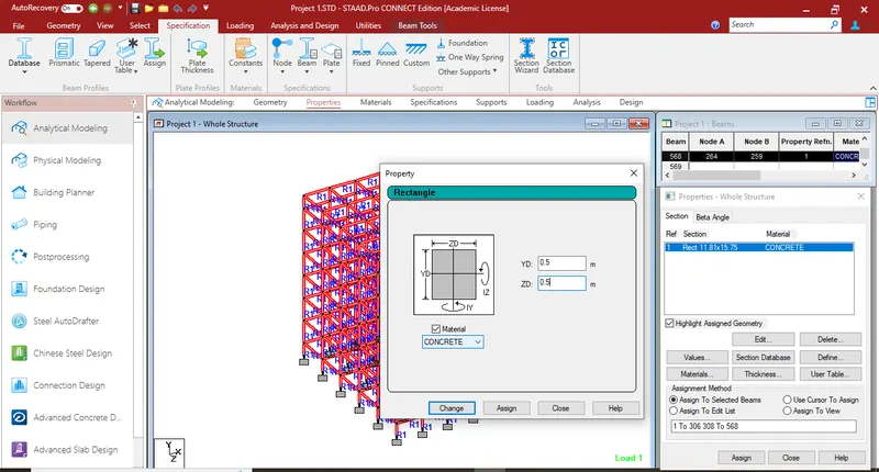
- So the dimensions are changed to make the structure pass the forces applied
- Revised structure is analised and the same procedure as shown above is perfoemed once again and BBS of all passed beams have been extracted.
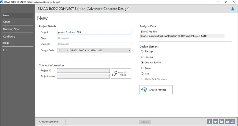
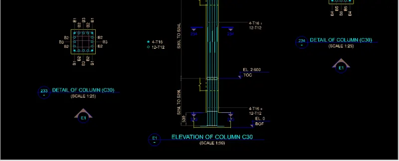
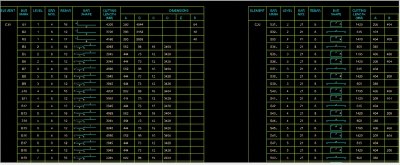
Bar bending schedule for columns
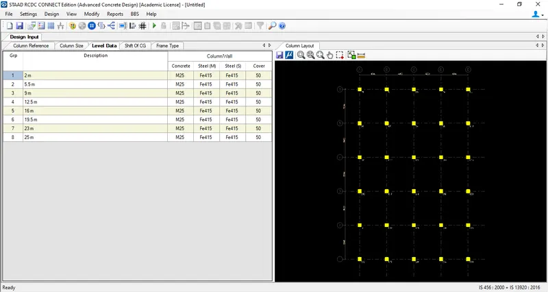
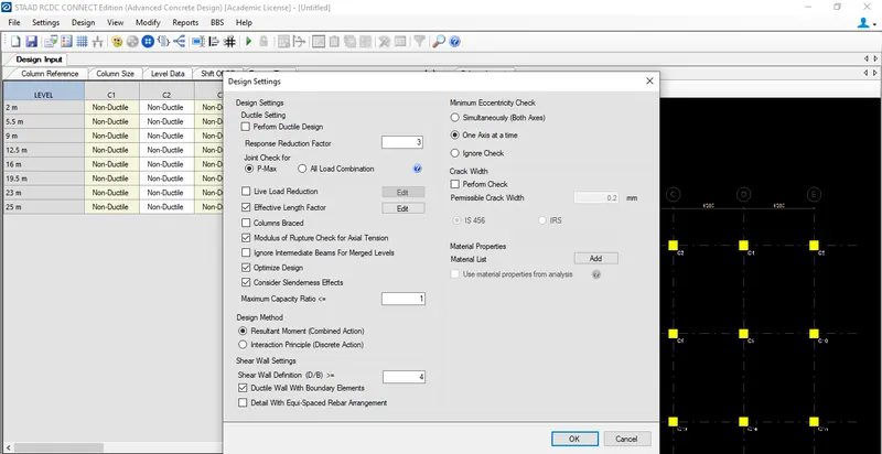
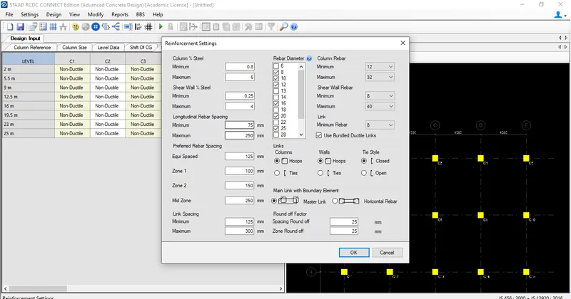
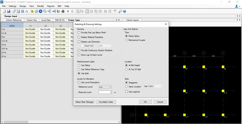
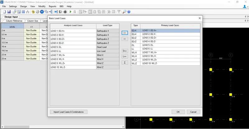
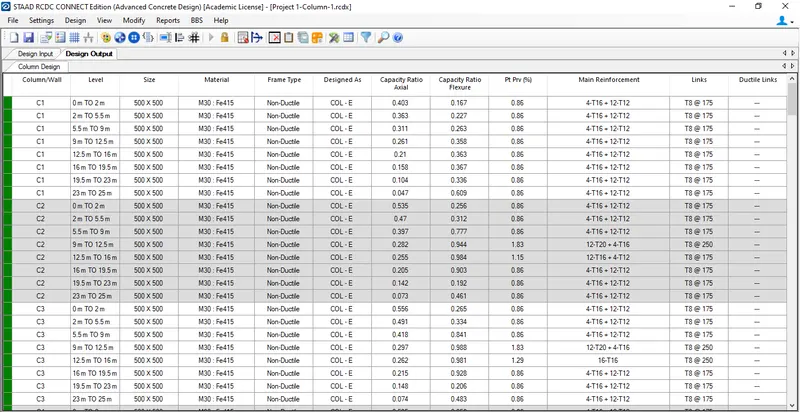
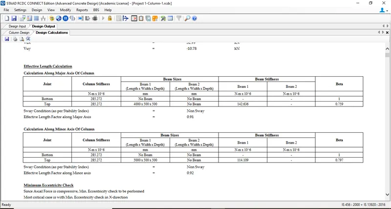
- A step by step procedure for column design in RCDC has been shown with the help of pictures below
- After analysing the structure, goto advanced concrete design which is present at the left side under workflow tab
- Select RCDC and select columns and walls
- Click on create project after giving it a name
- Now, RCDC takes all the required information from STAAD pro
- Noe, goto settings and give all the required settings such as grade of steel and concreet, clear cover etc
- Now, goto design tab and click on design
- A detailed design of columns can be seen and all the failed columns are shown with a red mark
- Calculations and others can be extracted from Reports tab
- Bar bending schedule can be extracted from BBS tab
Design of foundations using STAAD pro
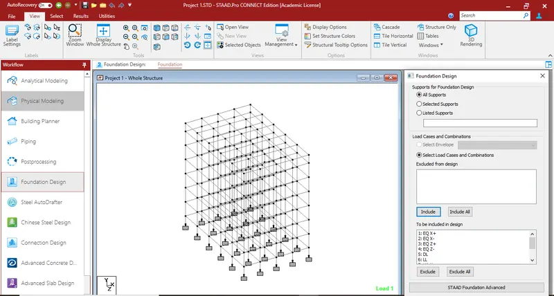
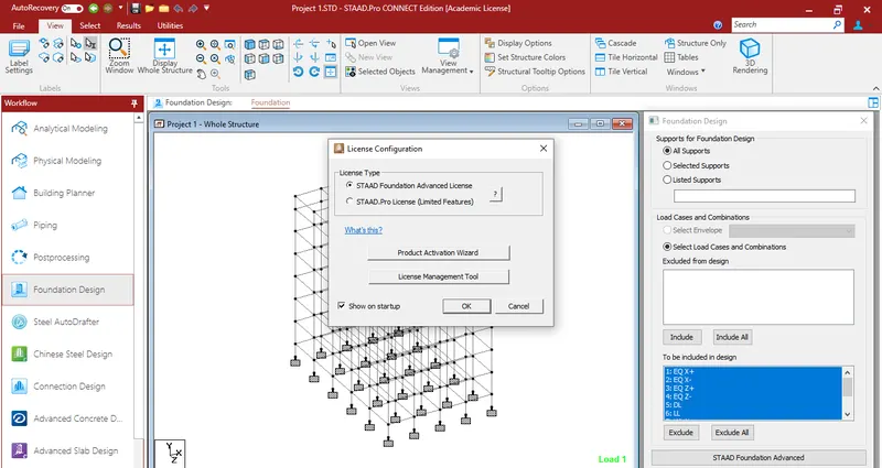
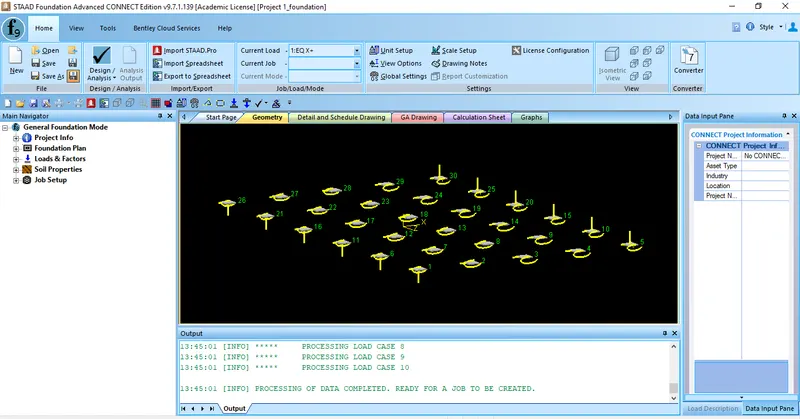
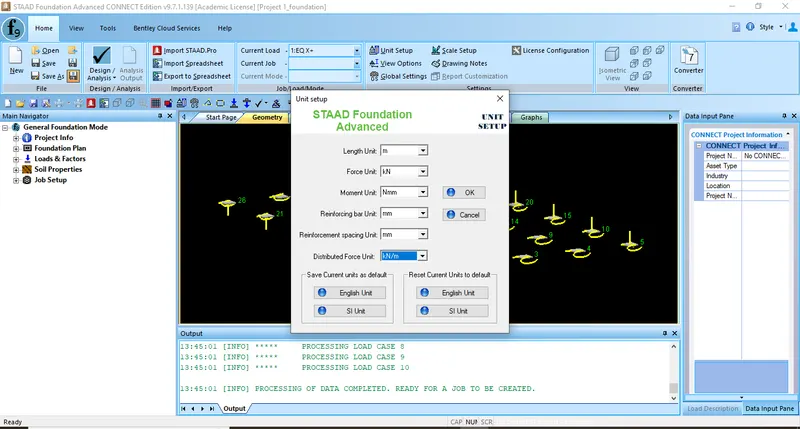
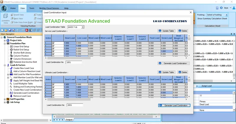
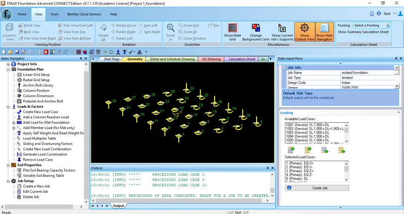
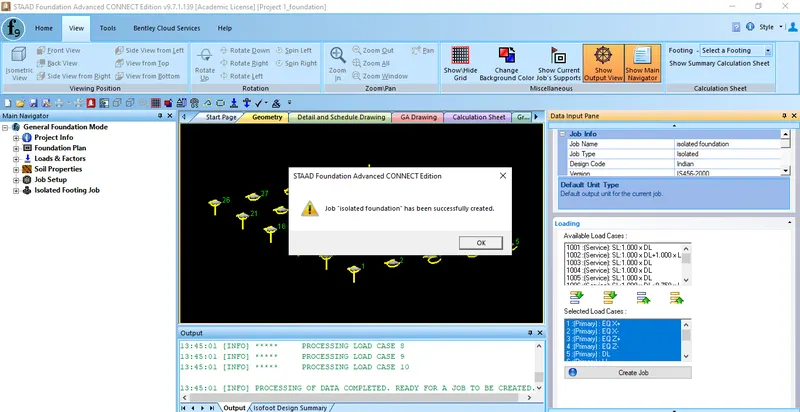
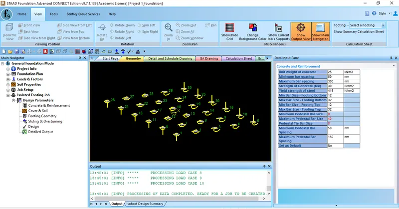
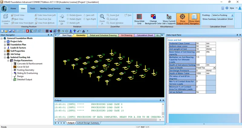
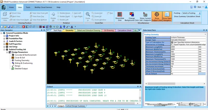
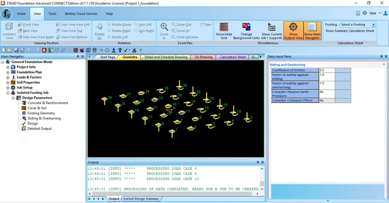
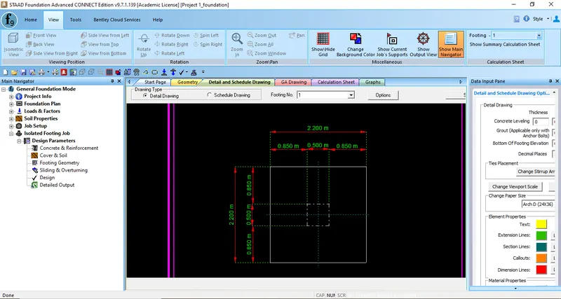
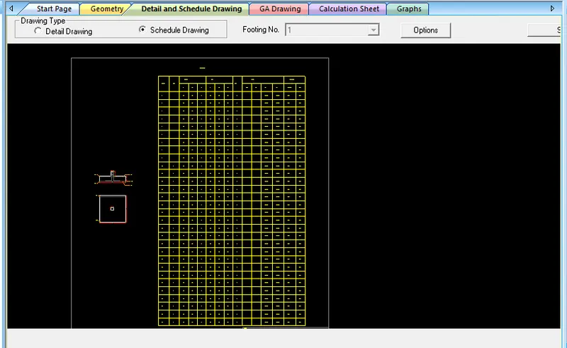
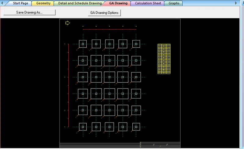
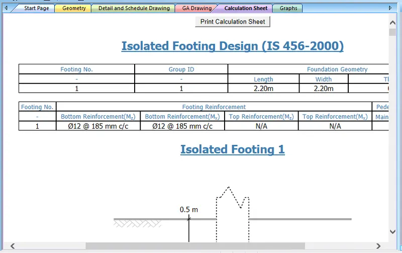
- A step by step procedure for foundation design in STAAD pro has been shown with the help of pictures below
- After analysing the structure, goto foundation design which is present at the left side under workflow tab
- Select RCDC and select columns and walls
- Now, foundation design connect takes all the required information from STAAD pro
- Now, goto units and change tothe required units and give all the required specifications such as grade of steel and concreet, clear cover etc
- Now, goto design in the main navigator bar present at the left side of the screen
- A detailed design of foundation can be seen
- Detailed and schedule drawings, General arrangement drawing and calculation sheets can be extracted from the tab above the working screen
Result :
A residential building of G+6+R has been designed successfully using STAAD pro, RCDC and STAAD foundation connect and all the reports such as calculations are added in the documents section including the STAAD pro file.