Project 1
1. Design a battery pack for a car roughly 150 Kw with 120 V. Use 3500 mAh 3.6V nominal NMC chemistry cell.
a. Design the battery pack configuration.
b. Draw the BMS topology for this battery pack.
Theory:-
Battery Management System :-
A Battery management system(BMS) is said to be the brain of a battery pack. The BMS isa set of electronics that monitors and manages all of the battery’s performance. Most importantly, it keeps the battery from operating outside of its safety margins. The battery management system is critical to the battery’s safe operation, over all performance, and longevity of battery pack. The primary function of the BMS is to protect the battery cells from damage caused by being overcharged or over-discharged. Additionally, the BMS calculates the remaining charge, monitors the battery’s temperature, monitors the battery’s health and safety by checking for loose connections and internal shorts.
The BMS also balances the charge across the cells to keep each cell functioning at maximum capacity.
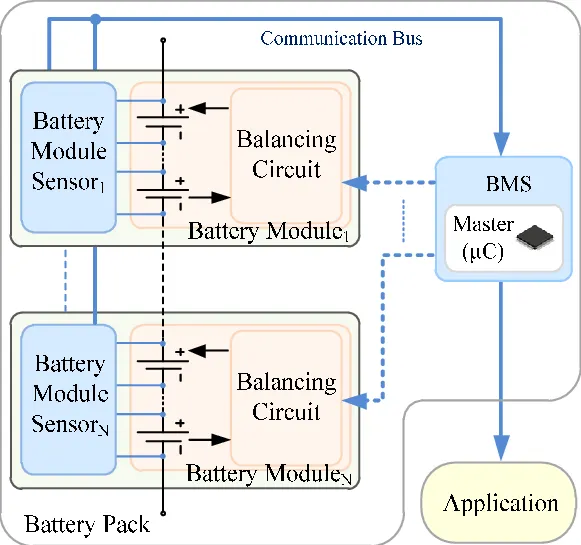
Fig: Battery management system
Solution :-
Given data:-
Required Power = 150 KW
Required Voltage = 120 V.
Battery details :-
Battery capacity = 3500 mAh= 3.5 Ah
Battery Nominal Voltage =3.6V
a) Design the battery pack configuration.
for designing the Battery pack Configuration ,Firstly we have to find the two parameters as follows :-
i) Number of cells connected in Series:-
For this solution let us Take the data from given:-.
Nominal voltage =3.6 v
Cell having capacity of cell(Ah)= 3500 mAh= 3.5 A
Formula :-
Cells connected in series = Required voltage (V) / Nominal cell Vol
From the data
Required Voltage :- 120 v
Nominal Voltage = 3.6 v
Therefore,
Cells connected in series = Required voltage (V) / Nominal cell Voltage(Ah)
The cells connected in series = 120 / 3.6
=33.3 cells
This Digits values are taken as rounding of calcutions as follows :-
Rounding of calculation:-
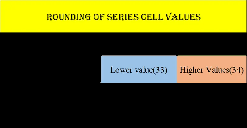
>>When compare with rated voltage, the battery voltage is greater in case 2 then case 1.
So,
No. of cell in series= 34S
Number Of Cells Connected IN Series = 34S -------------(1)
ii) Number of cells connected in Parallel:-
Formula for number of cells connected in parallel:-
Formula:-
Number of cells connected in Parallel = Required Continuous Current(I) / Ce
Given data:-
Required Power = 150 KW
Required Voltage = 120 V.
NMC Battery details :-
Battery capacity = 3500 mAh= 3.5 Ah
Battery Nominal Voltage =3.6V
We know that ,
Power(P) = Current(I) * Voltage(V)
from above formula;
Current(I) = power(P) / Voltage(V)
Hence, From formula;
Current(I) = power(P) / Voltage(V)
= (150 *1000) / 120
Current(I) = 1250 Amps
NMC Battery details :-
Battery capacity = 3500 mAh= 3.5 Ah
Battery Nominal Voltage =3.6V
Therefore,
Number of cells Connected in parallel :-
Number of cells Connected in parallel = Required Current (I) / Cell Nominal
from the data ,
Current(I) = 1250 Amps
Cell nominal Voltage = 3.6 V
Then ,
Number of cells Connected in parallel = Required Current (I) / Cell Nominal Voltage(V)
=1250 / 3.6
=358 P
Therefore
Number of cells Connected in parallel =358 P ................2
From values (1) and (2)
Number Of Cells Connected IN Series = 34S
Number of cells Connected in parallel =358 P
We can conclude that
The Battery pack Configuration = 34S358P
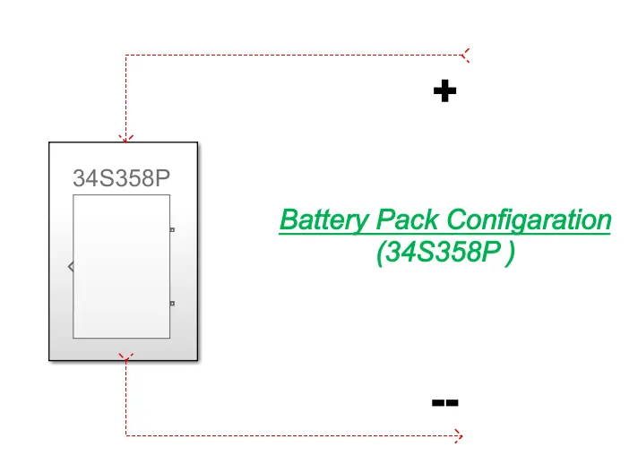
Fig: Battery Pack Configuration (34S358P)
b. Draw the BMS topology for this battery pack:-
BMS Topology:-
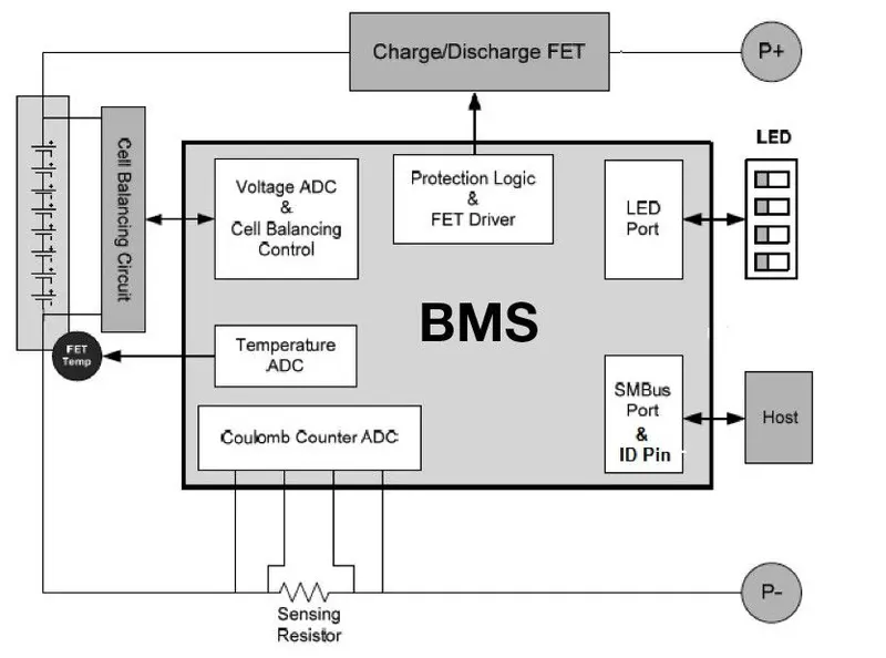
Fig:- BMS TOPOLOGY BLCOK DIAGRAM
Basically BMS topology is classified into following four(4) types:-
1)Centralized Topology:-
This Topology is used for only pack of 18 cells or less than 18 cells in a series only.
2)Master and Slave topology:-
This Topology is used for pack of 18 cells or grater than 18 cells in a series . High Energy storage purpose.
3)Modular Topology:-
This Topology is used for pack of 18 cells or grater than 18 cells in a series. Very large Large Energy storage purpose.
Solution:-
From the Architecture of BMS we can said that the "AFU" Allows only 18 cells connected in series per one unit of modulate.
Hence ,
we required series cells is 34 cells
Therefore we are dividing these 34 cells as 2 slave sets with 1 number of MCU master unit as follows
Slave 1= 17 cells
Slave 2= 17 cells
Based on this cells connected in series and Architecture of BMS we Choose the Master and Slave topology of BMS for this Ev battery pack Topology design.
BMS Topology MODEL :-
Master and Slave Topology:-
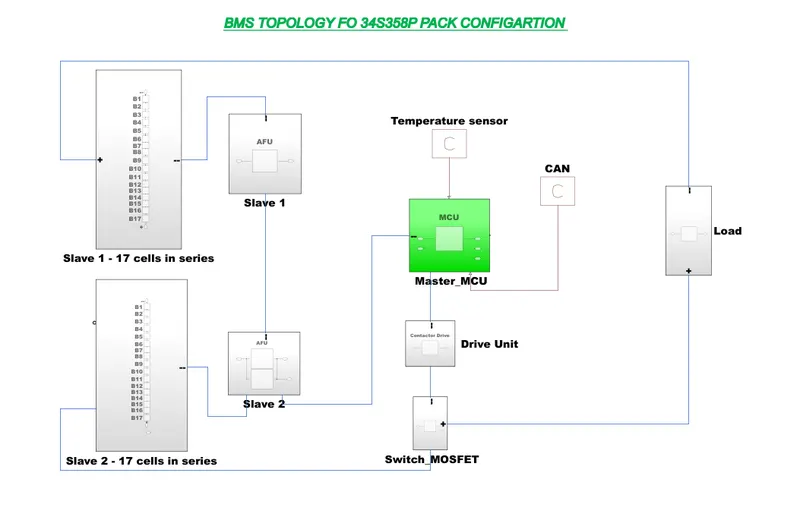
>> Above Model is For BMS Topology of 34s358P battery pack Configuration model
>>This Topology consists a 2 numbers of slave of AFU units with each AFU units slave Consists a 17 numbers Of Cells connected in series.
Conclusion :-
We can conclude from above calculations;
The battery Pack configuration is 34S358P.
Battery BMS Topology is "Master and Slave " Topology is designed and explained theory regarding BMS topology.
2)Build a 3S2P battery pack configuration with generic battery block using Matlab/Simulink.
Aim:-
The main aim is design a given battery pack configuration by using the Matlab/Simulink Tool.
Given data :-
Battery pack configuration = 3S2P
Simulink model :-
For creating the Simulink model battery pack configuration we are used following blocks:-
- Battery,
- scope,
Procedure:
Batteries in 3S2P configuration in Matlab/Simulink. That is 3 cells should be connected in series and 2 cells should be
connected in parallel.
Therefore,
Total number of cells in battery pack = No. of cells in series * No. of cell
Then ,
Total number of cells in battery pack = No. of cells in series * No. of cells in parallel
Step 1:-
Arrangement of 6 cells:-
The figure 1 shows the arrangement of 6 cells.
We have to place total number of cells in battery pack (6 cells)
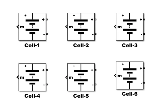
Figure 1: Arrangement of 6 cells
Step 2:-
Parallel connection:-
The figure 2 shows the batteries connected in parallel.
For parallel connection, batteries are connected from terminals to same terminals of other batteries that is positive terminal (+) of one battery is connected with positive (+)terminal of other battery and negative terminal (-) of one battery with negative terminal (-)of other battery.
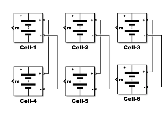
Figure 2 : Battery connected in parallel connection
Step 3:-
Series and parallel connection:-
The figure 3 shows the battery connected in series and parallel combination. Batteries are connected from terminal to terminal in a way that the positive (+) terminal of one battery is connected with the negative (-) terminal of the other battery and negative terminal (-) of one battery is connected with the positive terminal (+)of the other battery.
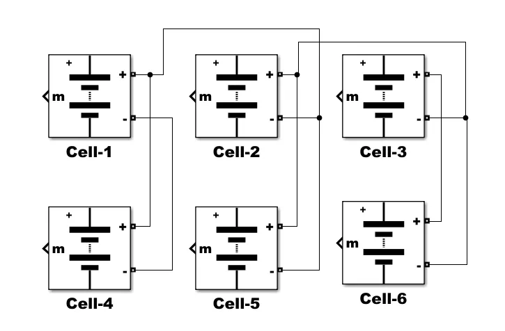
Figure 3 : Battery connected in series and parallel combination
Model Explanation:-
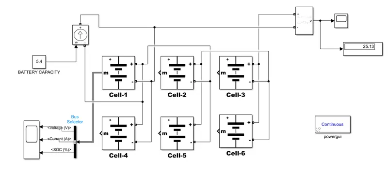
The voltage measurement block is connected across the battery pack to measure the battery pack voltage. The scope output used for the battery pack consists of SOC (State of Charge), Current and voltage. The controlled current signal is given as the load to the battery pack. The constant blocks determined with battery capacity and it is given to the controlled current block.
The parameter given inside the battery is given below:-
- Nominal voltage of a cell 7.2V
- Rated capacity of a cell 5.4Ah
- Maximum voltage of a cell 8.3V
Therefore ,
Nominal voltage of the battery pack = no. of cell in series * nominal voltage of a cell
= 3 * 7.2v
= 21.6 V
Rated capacity of the battery pack = no. of cell in parallel* rated capacity of a cell
= 2 * 5.4Ah
= 10.8Ah
The model is for an 21.6V 7 with 10.8Ah battery capacity
Overall voltage of the battery pack = maximum voltage of the battery * no. of cells in series
= 8.3V * 3
= 25 v
Overall voltage = 25 V
Total Battery pack model:-
Output Scope results :-
Voltage scope :-
Overall voltage of the battery pack = maximum voltage of the battery * no. of cells in series
= 8.3V * 3 = 25 V
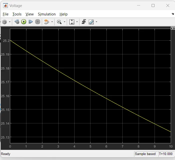
>>From the Above Plot is we can observe that the total battery pack voltage is reduced but 10% of the initial value.
Battery pack details:-
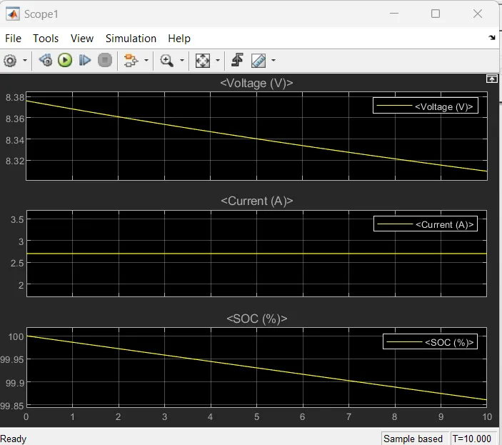
>> From the Above graph we can observe that the
Top Plot is (Voltage):-
>>The voltage is around 8.3V. The increasing and decreasing voltage is with respect to there generative braking
Middle Plot (Current):-
>> The current signal is determined by the load and the decrease in current is due tore generative braking.
Bottom Plot(SOC%):-
>>The SOC (state of charge) is started to reduce from 100% to 99 % corresponding to the load given
Conclusion :-
The battery pack configuration(3S2P) with generic battery block using Matlab/Simulink is created.