Week -2
PART 1:
In Simulink, we use blocks to represent any system to get the desired output. In this project, we use some blocks to get our desired output.
- Pulse generator: The Pulse Generator block generates square wave pulses at regular intervals.
- Simulink PS converter: It Converts the Simulink input signal into a physical signal.
- Switch: Switch controlled by an external physical signal.
- Battery: It gives the power to the close loop.
- Electrical reference: It shows connection to electrical ground.
- Solenoid: Electrical characteristics and generated force of solenoid.
- Ideal translational motion sensor: It is a motion sensor in mechanical translational system.
- PS- Simulink Converter: It converts physical signal into Simulink output signal.
- Mechanical Translational References: Reference connection for mechanical translational ports.
- Scope: It displays signals generated during simulation.
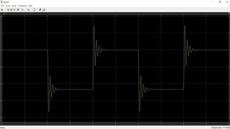
- From the above two graphs, we can observe that plunger is moved from its original position to some amplitude with a time delay of 2sec.
- Then it hit the bell and pause there for 2sec and come to its initial position.
PART 2:
Thermistor: A thermistor is a resistance thermometer or a resistor whose resistance is dependent on temperature.
Block used in model:
peating Sequence Stair
- Controlled Temperature Source
- Thermistor
- Resistor
- Voltage Sensor
- Battery
- Switch
- Scope
- Display
- PS- Simulink Converter
- Simulink-PS Converter
- Solver Configuration
Explanation:
- As per given condition for time and temperature give the values to the Repeating Sequence Stair and configure as per our condition.
- There is a Simulink PS converter that converts Simulink signal to physical signal.
- Give this signal to the controlled temperature source block which represents an ideal source of thermal energy that is powerful enough to maintain specified temperature.
- This signal then passes to Thermistor which connected to the battery.
- The voltage sensor is connected to a resistor which is used to measure the voltage as a threshold value for the condition of our circuit.
- We used the switch and provided a threshold value. If the signal value is greater than the threshold value, then turn it On otherwise it will be turned Off.
Output
- The Angular Velocity graph shows that if the temperature is 20deg.Celcius the fan is off for the first 10sec when the temperature reaches 2drg.Celcius then the fan is for the next 20 sec and when the temperature comes to 23deg.Celcius fan gets off.
Conclusion:
- We use the thermistor to sense the temperature, and according to the given condition, we put the threshold value to the switch for turn On and Off.