Week - 4
PART 1: Implement control logic of a washing machine” using State flow as per given sequence.
Solution:
- If the power supply is available, the system gets activated.
- If the water supply is not available, stop the process & indicate through LED
- The soaking time should be 200s followed by washing time of 100s.
- Then rinsing happens for the next 20s & dryer runs for 50s.
After all the processed have completed turn on the finished LED.
A washing machine is a machine used to wash various types of clothes without applying any physical effort. With a washing machine, you don’t have to rub the clothes with your hand to remove the water from them. The washing machine enables you to wash your clothes automatically without having to supervise its operation.
Stages of washing machine:
- Prewash
- Washing
- Rinsing
- Spinning
Modelling of washing machine in Simulink:
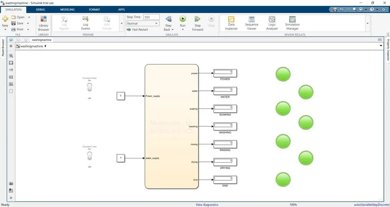
These are the following things we need for modelling the subs system of washing machine logical block settings:
- Toggle switch
- Constant
- State flow chart
- Lamps
- Display
Now following with steps involves in the process we go step by step:
- Switch OFF
- Power ON
- Water supply on
- Soaking
- Washing ON
- Rinsing
- Drying
- END process
This is what it looks like in the state flow chart:
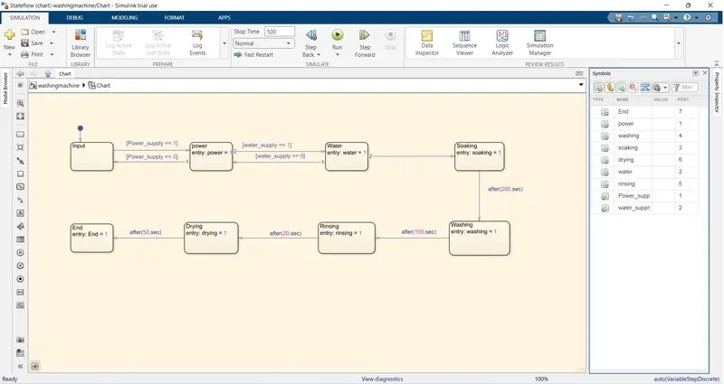
Just according to every step, we define here execute accordingly.
PART 2: Make a Simulink chart for the “Gear shift” logic as per below conditions:
Speed Range(kmph) Gear
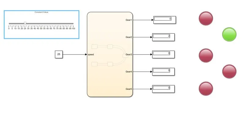
0 to 15 1
16 to 25 2
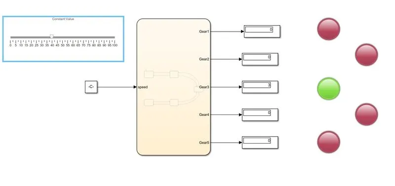
26 to 40 3
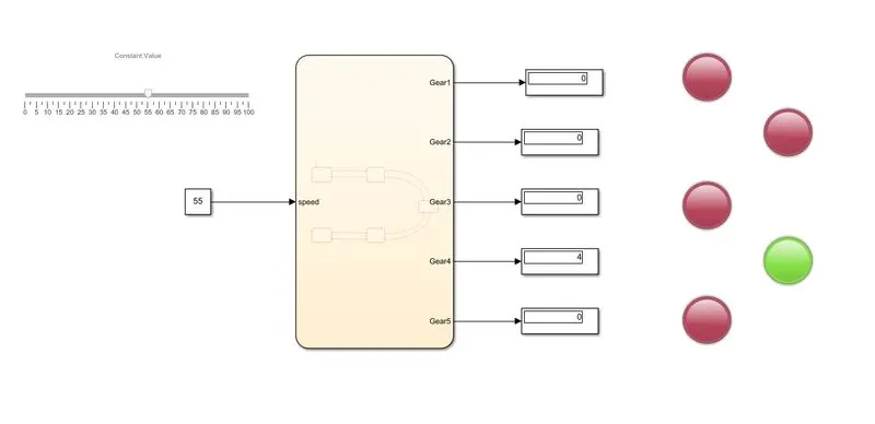
41 to 60 4
Above 61 5
Solution:
IMPLEMENTATION OF CONTROL LOGIC FOR GEAR SHIFT USING STATEFLOW:
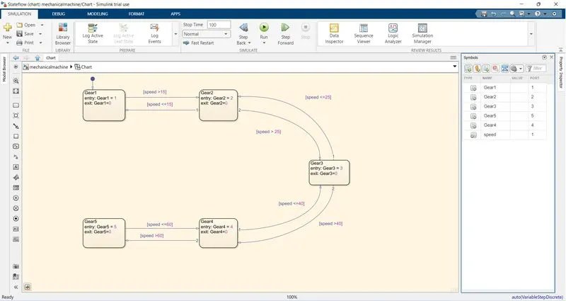
These are the following block setup did we need for the setup:
- State flow chart
- Slider
- Constant
- Display
- Lamps
PROCESS:
- Start Simulink and create a blank model.
- Search for CHART block in the state flow category of library browser.
- Open the chart block and select the various features from the state flow window.
The Transmission operating mechanism:
- To affect a gear change, selecting 1st first gear, for example: the driver depresses the clutch, disengaging the input shaft. Using the shift lever, the driver selects the first gear, and the linkage moves the shift fork to connect the 1st- 2nd locking collar with 1st gear, locking it to the output shaft. Now, when the clutch is released, engaging the input shaft, the output shaft turns because 1st gear is locked to the output shaft by the locking collar.
- As the driver speeds up, selecting 2nd, 3rd ,4th ,5th gear as well as and simply involved repeating the process.
And the output is just as similar as it is:
When speed 0-15 (Gear 1):
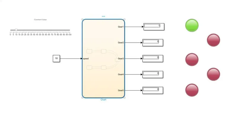
When speed 16-25 (Gear 2):
When speed 26-40 (Gear 3):
When speed 41-60 (Gear 4):
When speed above 61 (Gear 5):
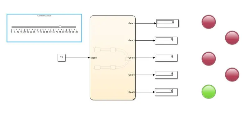
Conclusion: That's how we did the Gear shift logic in the Simulink. As we can see lamp glowing accordingly with gear it shows.