Project 1
Note : Please see the word and simulation files are attached.
Project 1 : Simulation and Design of Power Converters for EV using MATLAB and Simulink
Solution : In the above CCM (40V to 50V and 400V to 500V), Boost CCM (20V to 30V and 200V to 300V) and Buck DCM (10) are choosen.
- Buck CCM Converter : (Project No.1)
Buck converter in continuous conduction mode :
Buck converter does DC-DC conversion.
Buck converter step down DC voltage. It consists of Inductor, Capacitor and two switches which are Transistor and Diode. Transistor (Mosfet or IGBT based on application) is a switch that operates with on and off state. ON and OFF states get controlled by the gate signal.
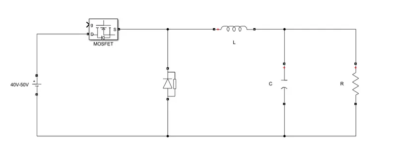
This is the buck converter used to convert DC to DC with step down operation.
|
Calculations : |
|
Vin |
L |
C |
|
40 |
0.00015H |
8.33 × F |
|
50 |
0.00024H |
8.33 × F |
The simulation circuit shows the Buck Converter.
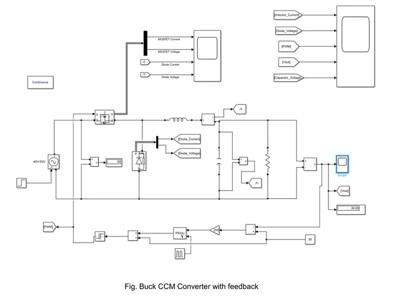
The result of simulation is shown below :
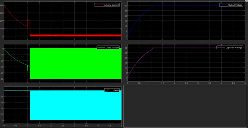
It shows that the output voltage 30V and the capacitor voltage is the same as output voltage.
The inductor current has resulted as 10A.
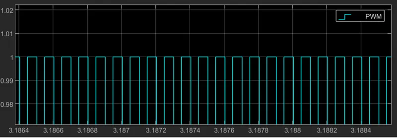
On and OFF operation of a switch is with the frequency 50khz and is shown in below.
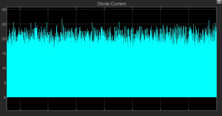
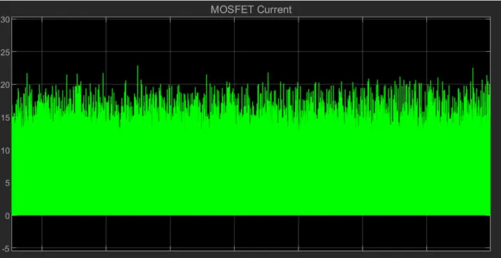
The Diode and MOSFET Current is shown below :
- Buck CCM Converter : (Project No.10)
If the same buck converter parameters are modified as the
Vin = 400 to 500V
Output voltage = 300V
Power = 3KW
Below are the rating requirments for the inductor, capacitor and rersistor.
Calculation :
|
Vin |
L |
C |
|
40 |
0.00015H |
8.33 |
|
50 |
0.00024H |
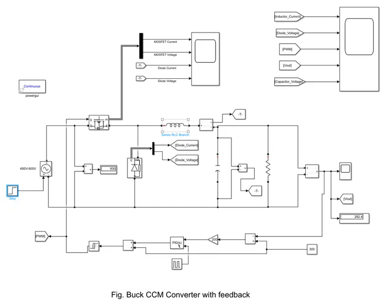
8.33 Matlab circuit simulation as shown below: |
Matlab circuit simulation as shown below:
The result of simulation is shown below :
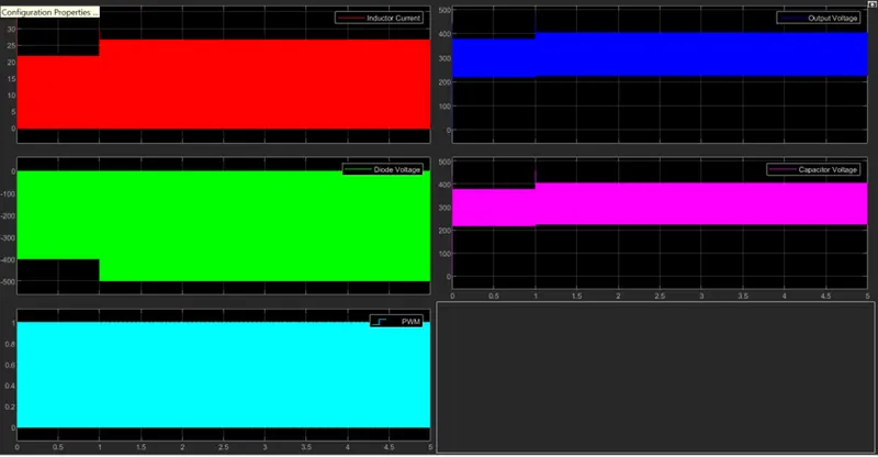
It shows that the output voltage 282.4V and the capacitor voltage is the same as output voltage.
The inductor current has resulted as 20.76A.
On and OFF operation of a switch is with the frequency 50khz and is shown in below.
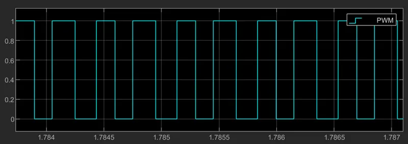
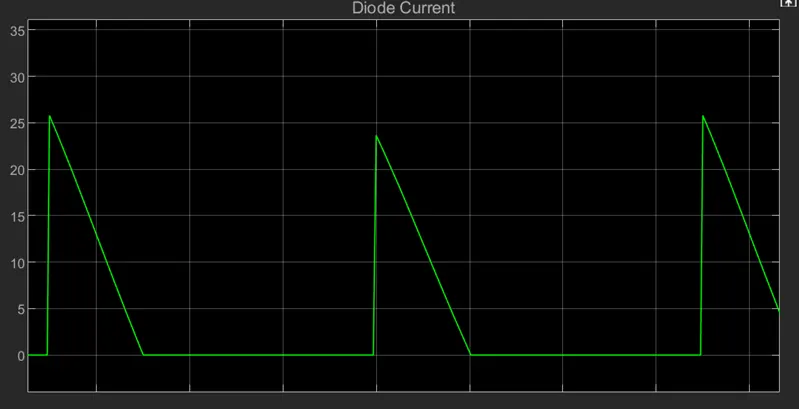
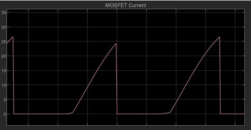
The Diode and MOSFET Current is shown below :
- Buck DCM Converter : (Project No.6)
Buck converter in Discontinuous conduction mode
Buck converter does DC-DC conversion.
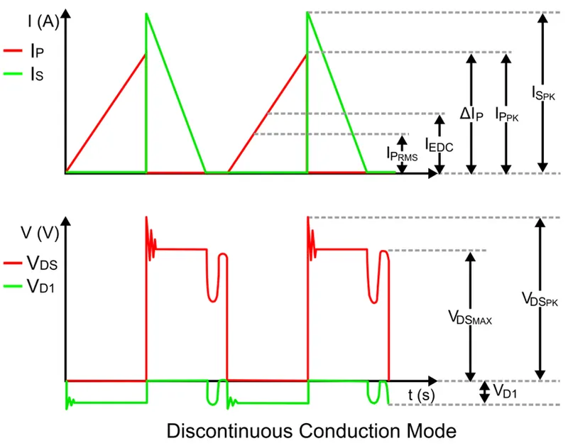
DCM offers higher efficiency than CCM, due to the lack of reverse recovery loss on the diode and a softer turn on of the MOSFET. However, if the duty cycle is too small, then the current that charges the primary inductor will be very high, which lowers the converter’s overall efficiency.
Calculation 4 :
Simulation design of Buck Converter :
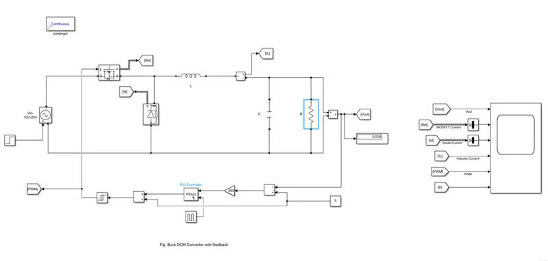
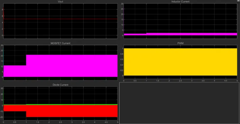
Simulation displays that the output voltage after the run simulation shows that the output voltage is reaching 5.018V.
Other results are as shown below.
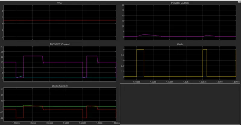
The zoomed results of the BOOST converter are shown in the above results.
It shows the output voltage is 5V diode current and MOSFET current are showing that the switches are operating alternatively and PWM signal is switching on the MOSFET into ON and MOSFET is OFF when PWM signal is OFF.
The above boost converter results if the input voltages are modified the results vary as shown below.
Result : Thus, we have successfully implemented the project 1 using different kinds of converters.