Design of Automotive Mechanical wiring Harness for engine
DESIGN OF AUTOMOTIVE MECHANICAL WIRING HARNESS FOR ENGINE
Master’s
Manufacturing Design
By
Avvaru Hari Tej
Skill-Lync
APRIL 2021
1.1 Basics of the electrical distribution system and wiring harness. 1
1.3 Typical design flow of EDS system.. 3
1.4 Wiring Harness Design Process. 4
1.5 Prerequisite to design wiring harness in CATIA V5. 5
3 PREPARATION OF HARNESS ASSEMBLY.. 18
3.2.1 Options in Route Definition: 22
3.2.3 Routing with external curve: 22
3.2.4 Modifying the wire harness bundle segment 23
3.2.5 Bundle segment definition: 23
3.2.6 Bundle Continuity Check. 23
3.2.7 Geometrical bundle warnings. 24
3.2.9 Important Tips & Techniques. 24
3.3 Wiring Harness Flattening. 27
3.3.1 Settings to do before wiring harness flattening. 27
3.3.2 Commands in Flattening workbench. 30
3.4 Wiring Harness 2D drawing. 32
4 WIRING HARNESS MOUNTINGS. 34
4.1 Different types of Clips & Applications: 34
5 WIRING HARNESS ROUTING AND PACKAGING RULES. 48
5.1 Design criteria for wiring harness. 48
5.2 Packaging rules and best practices. 49
5.3 Harness branching rules. 52
5.4 Guidelines for battery cables routing. 53
5.6 Water ingress protection. 54
5.7 Thermal Protection Management 56
5.10 Routing on/near Dynamic parts (Engine, Wheel) 59
5.11 Harness bending basics. 60
5.12 Interconnection connector management 61
6 WIRING HARNESS ROUTING OF ENGINE. 62
The automotive wiring harness is referred to as the central nervous system in the vehicle. It mainly consists of an electrical harness and the mechanical harness in the design. The current project is focused on the mechanical wiring harness and its rules and procedure to be followed while routing in the virtual condition. CATIA V5 electrical workbench is used as the CAD tool for routing the wires in the engine and tailgate components.
Some terms need to be understood before designing the wiring harness.
1.1 Basics of the electrical distribution system and wiring harness
Electrical Distribution System (EDS): It deals with physical (location of electronic components placed in the vehicle, front end to back end) and logical (different Electrical Control Units) architecture, schematic development, power distribution (set with fuses to check wiring harness is safe in various failure modes), wiring harness design and wiring harness component design of given electrical system.
E & E Architecture: It is a high-level logical connectivity diagram representing the number of systems, sub-systems, and logical connections between them. It is also extended to show the CAN (control area network) network between different electronic controllers.
Logical schematics: It is detailed design of E&E architecture which is extended to show the logical connectivity between different components and controls of different systems and sub-systems.
Electrical schematics: It is detailed design of logical schematics, which describe the pin-to-pin connectivity, properties, fusion distribution, grounding distribution, wire properties (wire type, colour, gauge), interconnects, circuit properties (circuit numbers, connector designation numbers, control device number), specification of component (rating od diode, resistors) etc., This is the end design of electrical core design of system and used as primary input for harness development.
Wiring harness topology: It is strategy to divide the harness between different pieces to achieve the best manufacturability, serviceability and cost-effective design.
Ex: engine harness, door harness, tail gate harness.
Note: Wiring harness cannot be repaired. It is advised to replace the damaged wiring harness parts.
Wiring harness routing: It is the desired path of wiring harness into given vehicle environment by applying set of design rules and industry best practices.
Wiring harness packaging: deals with the fixing/mounting strategy of wiring harness routing to ensure the safe, reliable and durability of wiring harness by applying set of design rules and industry best practices.
Virtual environment: 3D representation of vehicle components.
Benefits: 1) Huge cost saving, 2) Fuse failure avoiding, 3) Easy to predict i.e., warning in harness
Wiring harness is the assembly of different systems, sub-systems in the vehicle. It won’t have any function; it depends on its system and sub-systems. It used to pass the signals between components.
- Wires: Wiring harness consists of various wires bundled together, with each individual wire responsible for carrying electric signals and energy used ins tarting the engine, lights, meters, navigation system, Power windows and doors, and other devices in the vehicle. Wires are Cu conductors insulated with PVC insulation. Initiative in the industry to use the Al wire to get the benefits of weight and cost reduction.
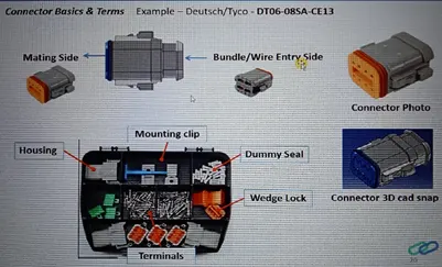
- Connector: An electrical connector, is an electro-mechanical device used to join Electrical termination and create an electric circuit. Electrical connectors consist of Housing, Terminal, Wedge Locks, Seals, Cavity, Mounting Cam etc., Connectors are plastic moulded housing with locking and retention features.
- Terminals: Terminals are defined as “A device designed to terminate a conductor that is to be affixed to a post, stud, chassis, another tongue, etc., to establish an electrical connection.” Terminals are metal (brass) conductor with plating (tin, silver, gold) constructed in specific shape to secure the joint from environmental conditions and with minimum electrical resistance.
- Protection device:
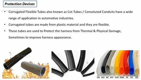
- Corrugated flexible tubes also known as Cot Tubes / Convoluted Conduits have a wide range of application in automotive industries.
- Corrugated tubes are made from plastic material and they are flexible.
- Theses tubes are used to protect the harness from thermal and physical damage, sometimes to improve harness appearance.
- Protection covering are flexible, temperature, wear and tear resistant moulded plastic/polymer parts.
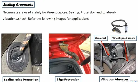
- Sealing Grommets are used mainly for three purposes. Sealing, Protection and to absorb vibration/shock.
- Protection Grommets are rubber moulded components used in wiring harness for protections.
- Insulations are adhesive/non-adhesive tapes and sleeves. They are made from PVC or cotton/polymer material. Cotton tape in high temperature area (engine).
- Clips and clamps: Wide variety of clips and clamps are available to mount the wiring harness.
- Fuse and relay box: are plastic moulded parts used to package Fuses and relays in systematic manner. It also protects them for any damage (Physical and Environmental).
- Retention device: are plastic moulded parts to mount connectors and other harness components. (Connector mounts, secondary locks, connector back shell etc). Primary locking is provided by the terminal itself; secondary locks are not mandatory but there are used to ensure that there is no damage. Back shells are the packaging devices which are used at the end of the connectors. It guides the wire to the connector in a constrain packaging area or to provide the better appearance at the end of the connector.
- Guiding channels: are plastic moulded or metal parts designed to guide harness bundle in given geometric area to secure and protect the harness.
- Electronic components: Diodes, terminating resistors, Flasher, Timer circuits are sometimes part of harness supply.
1.3 Typical design flow of EDS system
 |
|
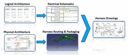
Figure 1: Typical design flow of EDS system. |
Logical Architecture, Electrical Schematics and Physical Architecture are designed by the electrical department whereas harness Routing and packaging is developed by mechanical department. Upon integration of electrical and mechanical departments final harness drawing is designed.
1.4 Wiring Harness Design Process
 |
|
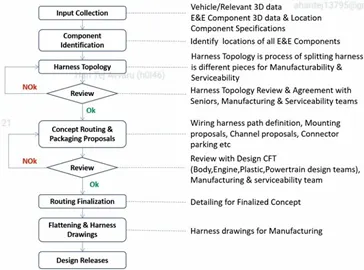
Figure 2: Wiring harness design process. |
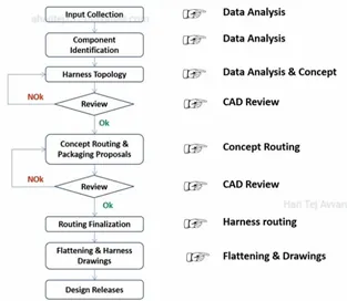
Figure 2 shows the wiring harness design process and its consideration at each and every step of the process.
 |
|
Figure 3: Wiring harness design process. |
1.5 Prerequisite to design wiring harness in CATIA V5
 |
|
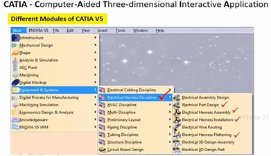
Figure 4: Important workbenches in CATIA V5. |
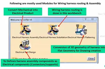
Fig. 4 and 5 shows the important workbenches that are required for the mechanical wiring harness routing.
 |
|
Figure 5: Definitions of electrical workbenches in CATIA V5. |
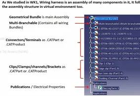
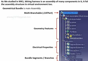
Figure 6 shows the feature tree that has to be followed while developing the wiring harness routing.
 |
 |
|
Figure 6: Feature tree in electrical workbenches in CATIA V5. |
|
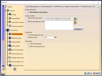
Fig. 7 shows the changes that has to be made in cache management. In working with large amount of data in order not to lose any data and open the workbenches quickly, work with cache system option is toggled on. The information from other departments can be easily open when this option in activated.
 |
|
Figure 7: Changes to be made in cache management. |
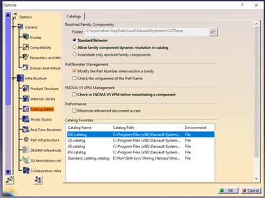
The catalog is a part storing document in which the parts which are frequently used in the modelling are stored and retrieved whenever it is required and at any location.
 |
|
Figure 8: Changes to be made in catalog editor. |
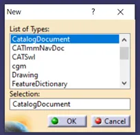
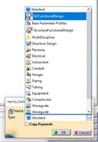
To create a new catalog, Go to New, select the catalog document. In catalog document create a family by using the add family option from Insert.
  |
|
Figure 9: To create catalog in catia. |
 |
|
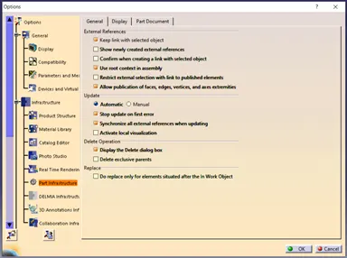
Figure 10: Part infrastructure options. |
 |
|
Figure 11: Electrical Harness management settings. |
 |
|
Figure 12: Electrical Harness management settings. |
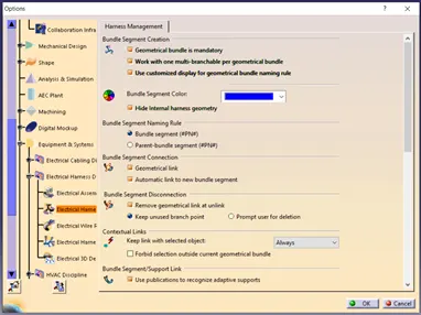
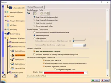
Fig 10. Shows the part infrastructure options that has to be toggled on/off before starting the wiring harness in CATIA. Fig 11 and 12 shows the electrical harness settings that has to be changed before starting the project.
 |
|
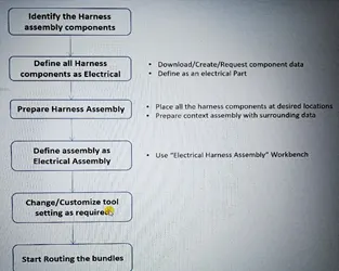
Figure 13: Design process for wiring harness routing of automotive vehicle. |
 |
|
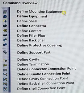
Figure 14: Command overview of wiring harness routing. |
Fig. 14 shows the different electrical harness routing commands that are available in the electrical part design workbench.
 |
|
Figure 15: Connector definition. |
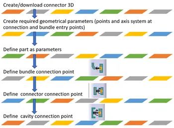
Fig. 15 shows the Connector definition and the detailed process. Fig 16 shows the different connector parts.
 |
|
Figure 16: Connector parts. |
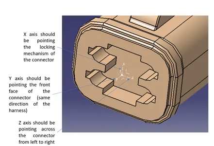
Geometry Parameters – Points and co-ordinate system (axis).
Connector connection points – This point is used for the connection of one connector to another connector.
Harness bundle entry point – This point defines where the harness bundle segment point will end when routed to the electrical connector.
Cavity connection point (optional): This point is used to define the connection of a connector to a connector clip. This only applies to connectors which have the mounting feature for a connector clip.
 |
|
Figure 17: Connector axis system definition. |
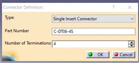
Once the bundle and connector entry points and axis system are created in part design workbench as shown in Fig. 17, switch to electrical part design workbench. In electrical part design workbench click on Define Connector option and click the connector and enter the type, name and number of terminations.
 |
|
Figure 18: Connector Definition. |
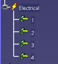
Change the termination names as 1,2,3,4 as given in the part.
 |
|
Figure 19: Termination name changed to 1,2,3,4. |
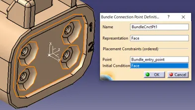
Now give the bundle connection point definition by clicking Define Bundle Connection and give the details as given in Fig. 20.
 |
|
Figure 20: Bundle definition. |
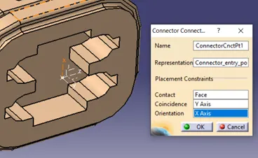
Now define the connector connection point definition by clicking Define connector Connection and give the details as given in Fig. 21.
 |
|
Figure 21: Connector definition. |
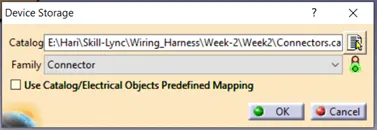
Add connector to catalogue. Click on store device command and select the connector catalogue that is already created and give type as connector and click on ok.
 |
|
Figure 22: Adding connector to catalogue. |
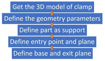
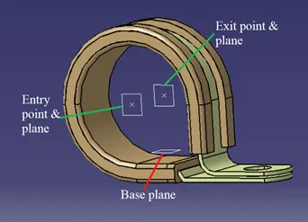
P-Clamp: This is another important component of the wiring harness which should be defined before wiring harness routing. Following are the important parameters that are required to be defined: Entry point and plane, Base plane and Exit plane.
 |
|
Figure 23: Defining clamp as support part. |
Clip has two entry points and two exit points. Create points and planes at the entry, exit and base of the clip using point and plane definition commands.
 |
|
Figure 24: Creating entry, exit and base points and planes. |
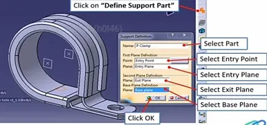
Now convert the part into electrical part using the define support command in electrical part design workbench and give all the details as shown in the Fig 24.
 |
|
Figure 25: Creating entry, exit and base points and planes. |
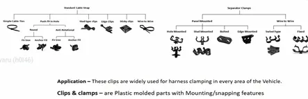
The different types of clamps are shown in Fig. 25
 |
|
Figure 26: Creating entry, exit and base points and planes. |
Back shells are plastic moulded parts used at wire entry side of connectors either for protection or to improve aesthetics/appearance of harness. These are not mandatory parts of wiring harness. Are always optional and driven by cost.
 |
|
Figure 27: Types of Backshell. |
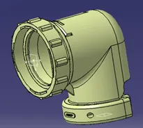
Download the 3D model of the backshell from the internet. Give the axis system in the same orientation of the connector connection point.
 |
|
Figure 28: Creating axis system at the entry of the bundle in backshell. |
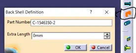
Switch to electrical part design workbench. Select the define backshell command and select the component. In the extra length option the required extra length can be provided.
 |
|
Figure 29: Creating axis system at the entry of the bundle in backshell. |
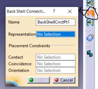
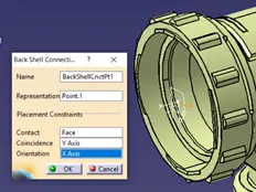
Define bundle entry connection point from connector in backshell.
 |
 |
|
Figure 30: Creating axis system at the entry of the bundle in backshell. |
|
Save the backshell into the catalogue so it can be used when ever it is required in wiring harness routing.
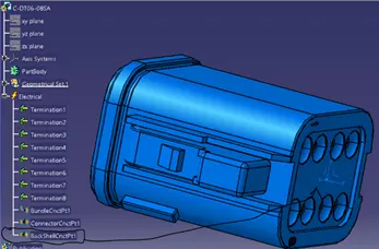
To add the backshell to the connector, define the backshell connection point to the connector at the bundle entry point of the connector same as mentioned in the Fig. 30.
 |
|
Figure 31: Creating backshell connection at connector bundle entry. |
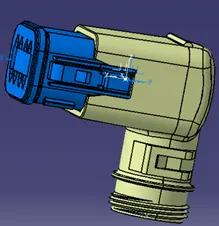
Switch to the electrical assembly design workbench. Create a product, copy and paste both the connector and backshell. In the electrical design workbench click on connect electrical devices command and select the backshell, the backshell point is highlighted when the backshell is connected. Now select the connector, automatically backshell point is highlighted. The connector and backshell are connected.
 |
|
Figure 32: Creating backshell connection at connector bundle entry. |
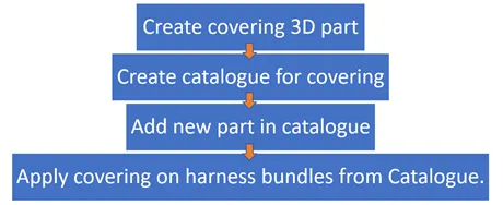
Corrugated tubes, Convolutes, Sleeves and many other types of coverings are used to protect the wiring harness. Graphical representation of coverings are applied on bundles.
 |
|
Figure 33: Creating Corrugated tubes. |
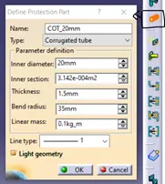
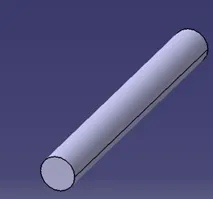
For creating corrugated tubes, switch to electrical part design workbench, click on protective covering definition and then select the plane where the corrugated tubes are to be created. A popup opens as shown in Fig. 34. Give the inner diameter, thickness and bend radius (generally 1.5 times the outer diameter) and click ok. The corrugated tube will be appeared on the screen. Save the part.
 |
 |
|
Figure 34: Defining the protective covering. |
|
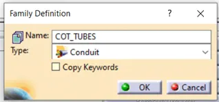
Now create a catalogue for COT tubes, so they can be used anytime it is required. In the family of catalogue select the conduit type as shown in Fig. 35.
 |
|
Figure 33: Creating Corrugated tubes. |
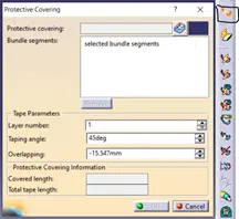
To add the protective covering to the bundle, switch to electrical assembly design, select the protective covering definition. Now select the bundle that requires the covering a pop up will open up as shown in Fig. 34. In protective covering tab, click on catalogue box and select the required COT tube.
 |
|
Figure 34: Protective covering. |
After selecting the bundle, the length of the tube can be changed by adjusting the start and end extremities point. This helps in fixing the COT tubes at a certain distance from the connector ends.
Insulations: are adhesive/non-adhesive tapes and sleeves. They are made from PVC or cotton/polymer materials.
 |
|
Figure 35: Tapings. |
 |
|
Figure 36: Creating insulation taping. |
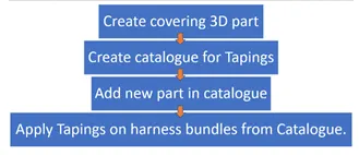
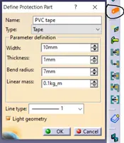
Creating the insulation tape is same as that of the corrugated tubes.
 |
|
Figure 37: Creating insulation tapes. |
Create catalogue same as corrugated tubes for PVC and cotton tapes and name it as insulations. Insulations are also added to the branches same as corrugated tubes by protective covering definition in electrical harness assembly workbench.
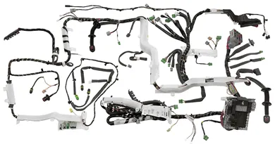
Guiding channels are Plastic moulded or Metal parts designed to guide harness bundle in given geometric area to secure and Protect harness.
 |
|
Figure 37(a): Guiding Channels. |
For channel Define it as Define Equipment in Electrical part Design Work bench. Now give the Bundle connection point to the channel (on both ends and at the channel guide ways). If channel is supplied along with the wiring harness, then it has to be in the Geometrical Bundle harness Assembly.
3 PREPARATION OF HARNESS ASSEMBLY
The harness Context Assembly: This is the top-level product file that contains the harness Geometrical Bundle/Assembly and the wire harness electrical bundle.
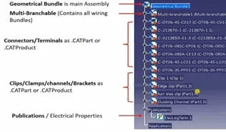
Geometrical Bundle: This sub level product file is the wire harness product that contains all of the harness components i.e., clips, supports, connectors, splices, grommets, annotation and actual physical bundle segments and branches.
Electrical Bundle: This sub level product file contains all of the electrical circuit information.
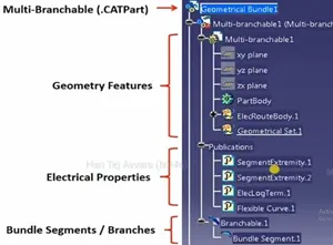
Geometrical Bundle is the important file that sets the wiring harness in the correct position. Any part selected wrongly in it can lead to damage the wiring harness.
 |
|
Figure 38: Multi-branch able content. |
 |
|
Figure 39: Geometrical Bundle. |
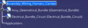
Create the product files as shown in Fig.40. In the present project the main focus is on Geometrical Bundle.
 |
|
Figure 40: Creating Assembly wiring harness context. |
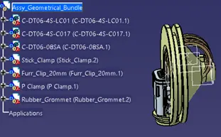
Take Assy_Geometrical_Bundle file into separate window and add all the required components such as connectors, clips, clamps that are necessary for creating the wiring harness.
 |
|
Figure 41: Adding components to the Geometrical Bundle Assembly. |
Now convert the Assy_Geometrical_Bundle into the electrical assembly file. The Wiring harness context will be same so as the surrounding CAD files can be added which is used for the review. Geometrical Bundle can also be act as main assembly product file in case of harness context is not necessary.
Switch to electrical harness assembly workbench and select the Geometrical Bundle command in it. Then select the Assy_Geometrical_Bundle product, the symbol of it changes to electrical harness assembly symbol.
Note: Ensure that all harness components that are needed in Assembly are Electrically defined with all required parameters before adding them in assembly.
TO create the multi branch able file. First ensure that all the components are electrically defined and placed in the correct position.
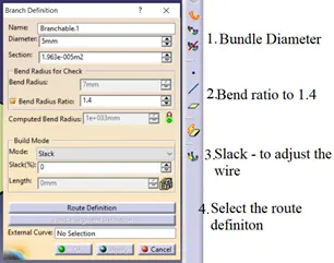
Switch to the Electrical Harness Assembly workbench. Click Multi Branchable definition just below the Geometrical Bundle command. Once you click it, Multi Branchable is added to the product file.
 |
|
Figure 42: Multi Branch Definition. |
In Build Mode, Mode options can be Slack, Length, Bend and Straight Bend. If slack is provided the bundle length will be increased according to the slack and the bundle will be easily routed. If length is provided, then CATIA overrides the calculated length of the bundle and adjust the bundle with the length given. In bend mode, the bend radius will be taken and the length will be calculated accordingly. In straight bend, bend radius will be neglected for the length calculation or it is kept minimum.
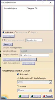
In Route Definition, only electrical components parts will be considered but with few changes non electrical parts will also be considered.
 |
|
Figure 43: Multi Branch Definition. |
Note: Create bundle selection separately. Do not select all the bundle selection at once which are in line with the branch.
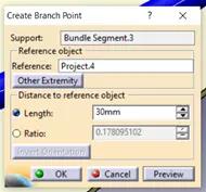
To add a branch point to the main bundle and extend the bundle from the branch point, in Multi branch able select the Add Branch Point Command and select the bundle segment on which the branch point needs to be added.
 |
|
Figure 44: Adding branch point to main segment. |
Once the branch point is given the main branch will be divided into two at the branch point. From the branch point, a new branch will be given. If there are any issues with the bend radius, add the slack in trial-and-error method, if still the red line is showing then it cannot be resolve by slack. Now try changing the direction of the bundle in any one of the components and check whether the bend radius issue resolves or not. If bend radius issue not resolve, then add one more clamp between them, then it will take smoothly.
Note: Branch point can be multiple selections. For one branching point we can add as many as branches.
Industrial rules for routing: 1. When there is a perpendicular surface there must be a clip provided at the top surface and also a clip provided on the vertical face.
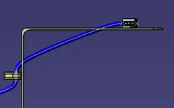
- Wring harness should not pass through any metal plate, it causes fouling. The fouling has to be checked before it is going for manufacturing.
 |
|
Figure 45: Harness fouling. |
To avoid fouling follow the following steps:
- Using external points: Select the branch where the routing is required by double clicking on it and select the route definition. In route definition, select the second component and click on Add Before option. Now press the Ctrl key, the point snap option activates and select the point where it is required and give left mouse click. The routing is changed to that position.
- Using clips: Clips can be added if the wiring harness is fouling.
3.2.1 Options in Route Definition:
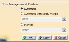
- Offset Management at Creation: Automatic- It won’t provide any clearance between the external selected point and the bundle segment.
 |
|
Figure 46: Offset Management at Creation. |
Automatic with Safety Margin – It provides clearance between the external selected point and bundle segment.
Manual – The distance between the external selected point and bundle segment can be given manually. To avoid fouling the minimum distance must be radius of the bundle.
Note: These offset management options must be given before the creation of the point.
- Tangency Management:
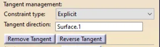
The tangency for clamps and clips will be already defined so this option won’t be seen. For connectors predefined explicit option is selected. For the externally selected point tangency can be given From Curve and can select the surface in which the bundle segment should present.
 |
|
Figure 47: Tangent management. |
Note: Tangency need not to be defined for the Electrical defined components (connectors, clips, back shells) because it is defined with electrical properties.
3.2.3 Routing with external curve:
There is another option to route the bundle without selecting any Electrical objects or without defining Routing Points on surfaces, i.e., Routing with External Curve.
 |
|
Figure 48: External curve. |
3.2.4 Modifying the wire harness bundle segment
The modifications allow you to change the bundle diameter, slack, length, shape, tangency direction, repositioning of the bundle node points and the deleting of bundle segments.
3.2.5 Bundle segment definition:
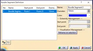 |
|
Figure 49: Bundle segment definition. |
In bundle segment definition, the start and end points cannot be changed, the colour of the selected bundle can be changed accordingly. If bundle segment definition is taken between the branch point, the branch point distance can be changed accordingly.
To delete the branch segment, go to electrical installation workbench and select the branch segment and click on Delete Special command, the bundle will be deleted.
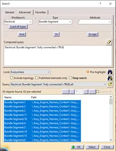
Go to Edit, Select the Search, in search go to Advance. In Advance, in workbench select the Electrical, in Type select the Bundle Segment, in Attribute select the Fully Connected option.
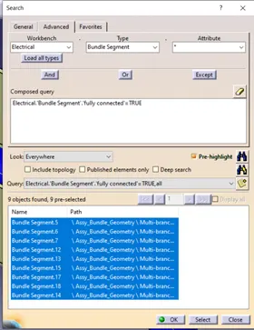 |
|
Figure 50: Bundle segment continuity check. |
3.2.7 Geometrical bundle warnings
It is possible to get warnings when routing your wire harness. These warnings are usually displayed in the tree structure of the wire harness geometrical bundle.
These warnings are usually related to the bend radius, bundle diameter or the vector position of your bundle segments. If there are any issues with the above then a yellow flash warning symbol will appear in the tree structure of the geometrical bundle.
Note: To solve the warnings given by the bundle segments, the clips and connectors positions can be changed. In case if it is not possible to change the positions, then by using Tangent management of external points with the external lines form curve, the error can be resolved.
The 3D annotation is used on the wiring harness to show connector functions and additional notes.
Connector function annotation: This annotation is to be added to the connectors to show the function of the connector unit it is connecting to. This is useful for other design departments who requires the 3D harness models but aren’t familiar with the harness connector functions.
Wiring harness drawing notes: This annotation is to be added to the harness data to show specific information relating to the harness (wire type, wire specifications, or any additional information/comments that need to be specified).
Creating the annotation:
- Switch to Assembly Design Workbench.
- Make sure the Geometrical Bundle is Active.
- Select the front view/ annotation plane icon.
- Select the plane for the annotation.
- Select the flag note with ladder icon.
- select a reference point to add the annotation.
- Input the connector function name.
- Select ok.
 |
|
Figure 51: Annotation tool bar. |
3.2.9 Important Tips & Techniques
- Link / Unlink Harness Elements: Used to create link and remove link between harness assembly. It is available in Electrical Harness Assembly workbench. When Link command is selected and the required bundle segments are selected, a new window pop up asking whether to create tangency continuity between bundles, it is recommended to select the option because CATIA can calculate the length, bend naturally between the bundles. It is mainly used to create different concepts, so that the optimal can be selected for the final review.
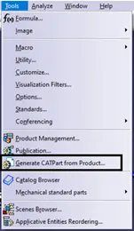
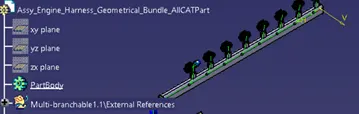
- Creating a CAT part from harness Product Assembly: Sometimes it is necessary to create a CAT part of the 3D wire harness for Review or releasing purposes. This CAT part can be converted as IGES or STEP.
Go to Mechanical Assembly Workbench, Tools, Generate CATpart from Product.
 |
|
Figure 52: Generative CATpart from product. |
- Measuring harness bundle segments: When measuring the harness bundle segments you should use the branch definition option. This gives you the exact measurement for each bundle segment node point i.e. the centre of a clip to another node point.
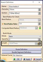 |
|
Figure 53: Bundle segment length. |
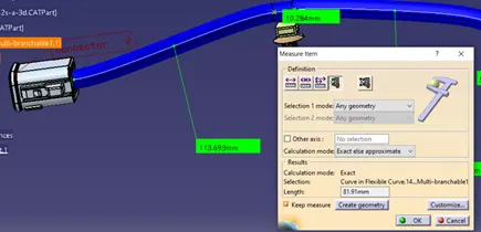
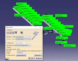
Use measure item command to use harness Curve lengths. Ensure that all Curves are visible.
 |
|
Figure 54: Bundle segment length using Measure item. |
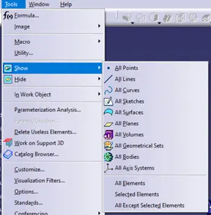
- Hide basic geometry: Once you have completed the routing of the wire harness you must ensure that all basic geometry i.e., points, lines, curves, planes, sketches, axis system et are all hidden before the wire harness product file is saved.
The second level of the multi branchable1 document must be selected.
 |
|
Figure 55: Hide/Show options. |
- Updating the context assembly and all sub-assemblies: Activate the context assembly. (Ensure that all surrounding data from other departments is deleted from the context assembly). If the context assembly requires an update, then you will see that the update all icon from the Catia workbench is available. Select the update all icon. The context assembly should now be all updated.
 |
|
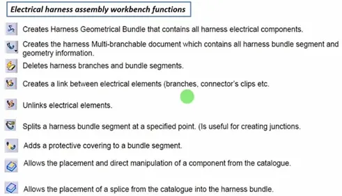
Figure 56: Electrical Harness Assembly workbench commands. |
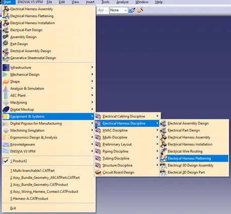
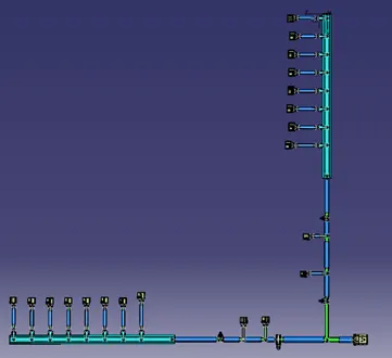
This helps to create the 2D drawing of the wiring harness. Switch to Electrical Harness Flattening workbench, which is located in Equipment & systems and Electrical harness discipline.
 |
|
Figure 57: Electrical Harness Flattening Workbench. |
3.3.1 Settings to do before wiring harness flattening
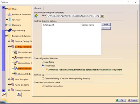
- Addition of catalogue: Usually in OEM catalogues are created to store the harness.
 |
|
Figure 58: Addition of Catalogue to Electrical Harness Flattening. |
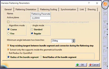
- Setting the harness flattening parameters: In the new product you have just created select the Harness Flattening Parameter icon from the Catia workbench. Select the General Tab and use the settings.
 |
|
Figure 60: Harness Flattening parameters – General Tab. |
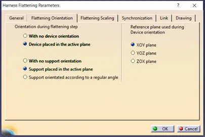
Keep the Flattening Orientation by default.
 |
|
Figure 61: Harness Flattening parameters – Flattening Orientation Tab. |
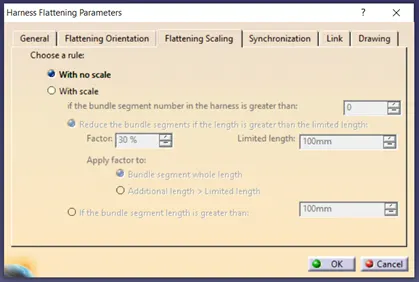
Flattening scaling can be kept as with no scale, so large routing can be taken place. With scale the harness routing will be changed to specified scale.
 |
|
Figure 62: Harness Flattening parameters – Flattening Scaling Tab. |
In the Drawing Tab, the connector, bundle and protective covering representation can be chosen.
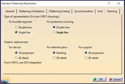 |
|
Figure 62: Harness Flattening parameters – Drawing Tab. |
Note: 1. Flattening should be saved in the same folder from where the wiring data is to be fetched.
- To import the wiring harness assembly into the flattening make sure that the windows are tiled vertically, so it is easy to import.
3.3.2 Commands in Flattening workbench
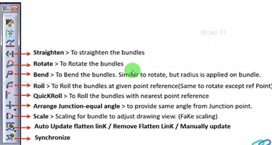 |
|
Figure 63: Harness Flattening Commands. |
To import the assembly wiring harness, Click on Flattening product, select the Extract command just below the Harness parameters and select the Assembly wiring harness. The assembly wiring harness will come to it. Once it is added to the Flattening workbench it will be changed into the “_Ehf” assembly at the end.
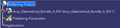 |
|
Figure 64: Harness Flattening Assembly converted to _Ehf. |
First use the Flatten command to flatten all the bundle segments.
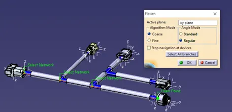 |
|
Figure 65: Harness Flattening Flatten command. |
In Rotate command, make the selection near the branching point not at the connector end.
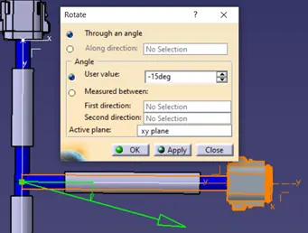 |
|
Figure 66: Harness Flattening Rotate command. |
For Roll command select the bundle which has to be roll, the bundle segment comes to vertical position and now click on screen in which side the roll is required and give the angle in the pop-up window.
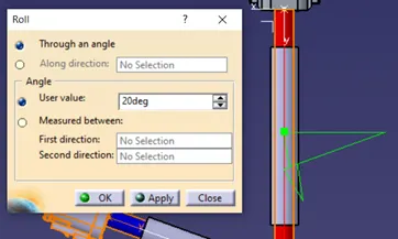 |
|
Figure 67: Harness Flattening Roll command. |
Note: If any changes are made in the Geometrical bundle assembly, to reflect it in the flattening workbench Synchronize command has to be given.
Take a new file and select the drawing type file. Always take the front view.
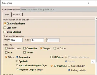 |
|
Figure 68: Harness drawing properties. |
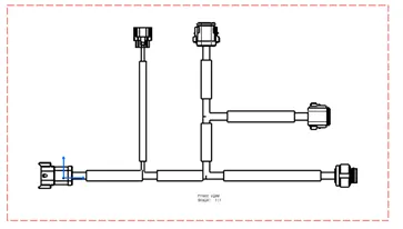 |
|
Figure 69: 2D drawing of Geometrical Bundle Segment. |
Following data is necessary on OEM drawings:
- Drawing Templates & details (Part number, Rev, stae holder, Sheet details)
- Harness Layout/Line diagram or Flatten drawing
- Dimensions
- Connector views (Wire Entry)
- Fuse & Relay box view & component placement details, Label views.
- Protection & size, Location & Representation of type of protection used.
- Bill of material (Part number, Vendors details, Quality, Size, Applicability)
- Connection Table / Circuit Table with wire specifications (Gauge, Type, Color, length)
- Wire Cut list (Circuit numbers and length)
- orientation, Position of all fixing parts.
- Generic notes for specification of devices (CAN Cables, Twisting).
Necessary data for harness drawing:
- There could be multiple sheets for harness drawing to represent the above-mentioned data.
- Sheet 1: Layout and dimensions, symbols, connector details, protection devices, Notes, Fuse and relay box views, Label views.
- Sheet 2: Connection Table.
- Sheet 3: Bill of materials (BOM).
- Sheet 4: Component orientation and assembly instructions.
4.1 Different types of Clips & Applications:
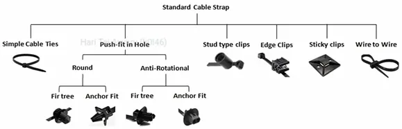 |
|
Figure 70: Types of Standard Cable Strap. |
Simple Cable Ties are used in combination with Fir tree or Anchor Fit. Fir tree provides the multi locking while Anchor Fit can be removed with a push force. Stud type clips are simply pushed into the hole. Edge clips are costlier than any other clips and mounted on the panel edges. Sticky clamps are stick to the flat surface of the body. Wire to wire is used to clamp one bundle to the other.
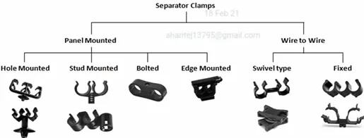 |
|
Figure 71: Types of Separator Clamps. |
These clips are used to route harness along with pipes/hoses/lines or to route two harness bundle parallel. There will be positive clearance between the bundles when routed with separator clamps.
The clips are taped with harness bundle and used to create an offset with mounting point. To keep harness portion straight in given portion.
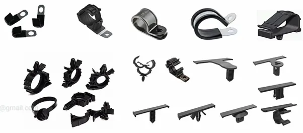 |
|
Figure 72: Clips. |
Fir Tree Mount and Cable Tie Assemblies: The mount can slide along the strap of the tie for proper orientation. The fir tree mounts are designed to provide a low insertion force and high extraction force.
High temperature fir tree mounts and cable tie assemblies provide excellent resistance in operating temperatures up to 275°F (135°C), while still maintaining tensile and retention strength properties.
Fir tree mount tube clip: Designed to offer a durable single-hole mounting, this tube clip allows the installer to insert the fir tree with minimal force while providing a secure hold.
C Clip with Fir Tree Mount: The unique fir tree design allows for easy insertion of the clip into a pre-drilled hole. Once installed, the cable can be quickly snapped in place for a secure fit.
Automatic harness clips – Non-connectable: These clips offer a simple and secure method of attaching cables to panels. They can be attached to the panel prior to installing the cables. Simply pushing the cable into place closes the clip and activities the automatic locking feature.
Cable Tie Mounts: Designed to provide stability to wire bundles. These mounts can accommodate miniature, intermediate, or standard cross-section cable ties. Each mount is secured with a single screw.
Dual Clamp Ties: Dual clamps ties are designed to provide parallel separation between hoses, wires, cables and tubing, protecting them from abrasion. These ties have an optional mounting hole for securing bundles along the chassis. The unique, one-piece design feature the dual head centred on the strap.
Cable Ties and Edge Clips: Designed specifically to route bundles by securing them to the edge of a plastic or metal sheet without the need for a mounting hole. The clip is easy to secure and the extraction force is high due to the integrated metal clamp that hold the edge clip in place.
Dual Swivel: These saddle spacers are installed between two to separate them and prevent them chafing and wear. The mounts can be easily rotated at any angle. Cable ties, which secure the bundles, are used with the mounts. The “H” profile of the saddles allows for broad surface contact with the bundle, minimizing pinching and crushing of the bundle.
Automatic Harness Clips – Connectable: In addition to offering the same simple and secure method of attaching cables to panels as the non-connectable automatic harness clips, these products can be connected for additional installation flexibility.
Omega Clip Cable Ties: Omega Clip Cable Ties provide the opportunity to attach a wire or hose to an existing bundle. Offering a full range of orientations, the wire/hose can be oriented in any direction in relation to the main harness.
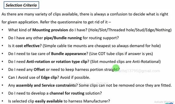 |
|
Figure 73: Selection Criteria of clips-I. |
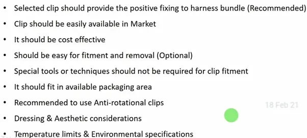 |
|
Figure 74: Selection Criteria of clips-II. |
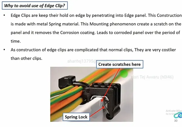 |
|
Figure 75: Why to avoid Edge clips. |
 |
|
Figure 76: Clips and Clamps providers. |
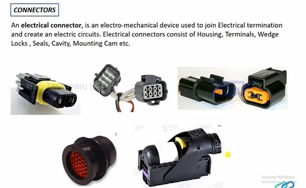 |
|
Figure 77: Connectors. |
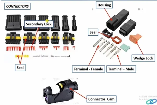 |
|
Figure 78: Connectors parts. |
 |
|
Figure 79: Connector Specifications. |
Sealed – Area where water leakage may occur.
IP69 – Widely used rating where the water jet splashes are high.
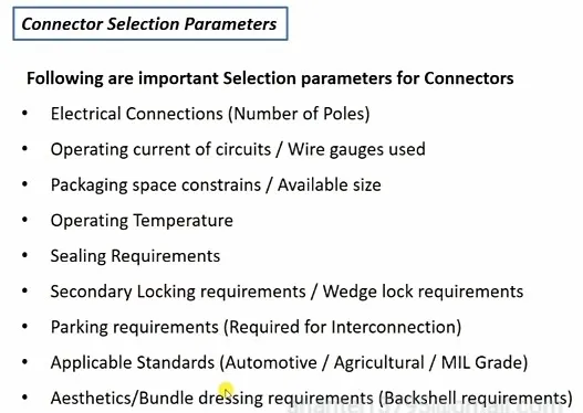 |
|
Figure 80: Connector Selection Parameters. |
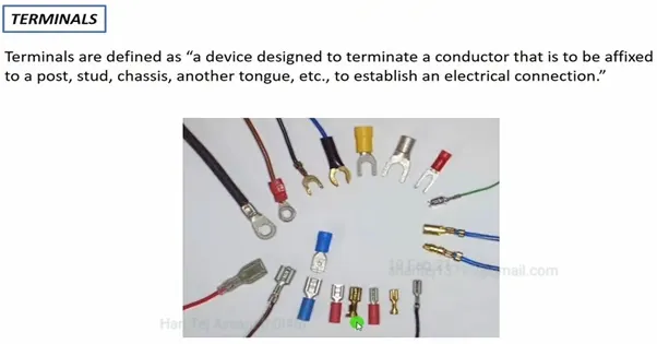 |
|
Figure 81: Terminals. |
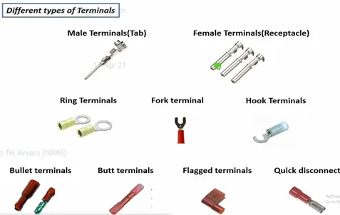 |
|
Figure 82: Different types of Terminals. |
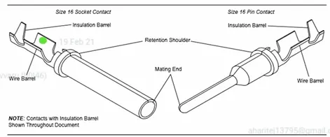 |
|
Figure 83: Male and Female Terminals. |
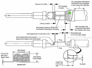 |
|
Figure 84: Crimping of Terminals. |
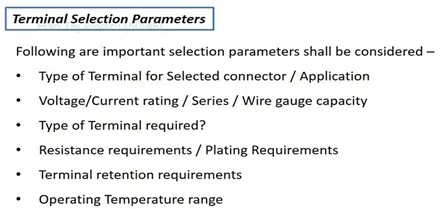 |
|
Figure 85: Selection of Terminals. |
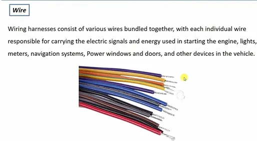 |
|
Figure 86: Wire. |
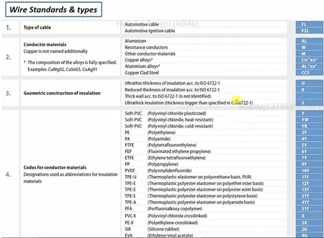
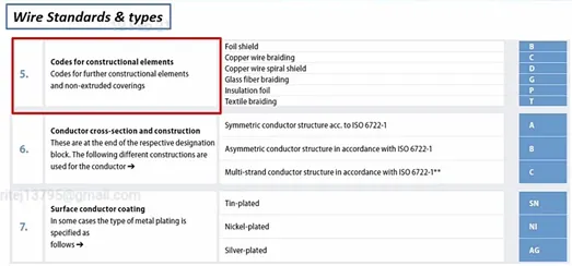
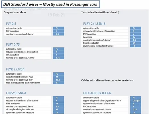
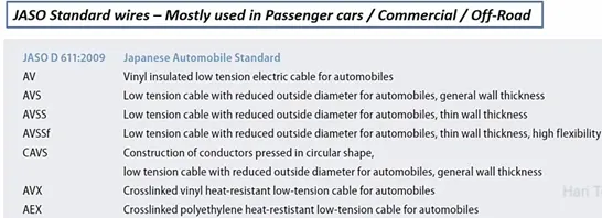
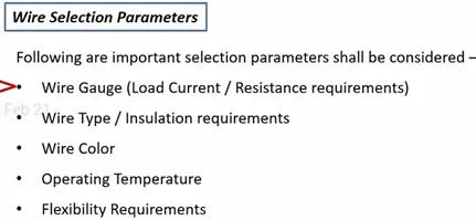
Wire Specifications:
- Standard / Grade
- Current carrying capacity
- Resistance per meter
- Insulation type/ Material
- Colour of Wire
- Temperature rating
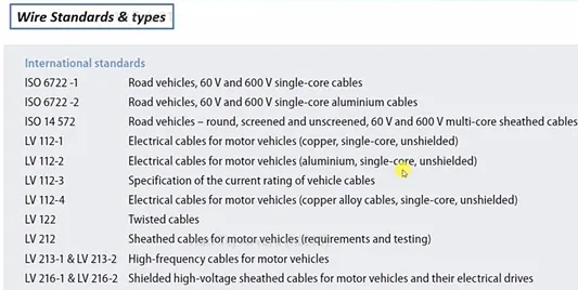 |
|
Figure 87: Wire Standards and types - I. |
 |
|
Figure 88: Wire Standards and types - II. |
 |
|
Figure 89: Wire Standards and types - III. |
 |
|
Figure 90: DIN Standards. |
 |
|
Figure 91: JASO Standards. |
 |
|
Figure 92: Wire Selection Parameters. |
 |
|
Figure 93: Protection Devices. |
 |
|
Figure 94: Protection Devices Specifications. |
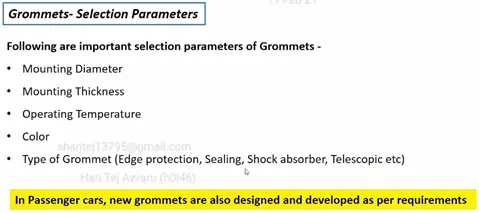
Selection Parameters:
- Size / Diameter
- Type of Protection Devices (Based on requirement)
- Temperature Range
- Abrasion resistance requirements
- Colour requirements
- Cost Considerations
 |
|
Figure 95: Sealing Grommets. |
 |
|
Figure 96: Sealing Grommets – Selection parameters. |
5 WIRING HARNESS ROUTING AND PACKAGING RULES
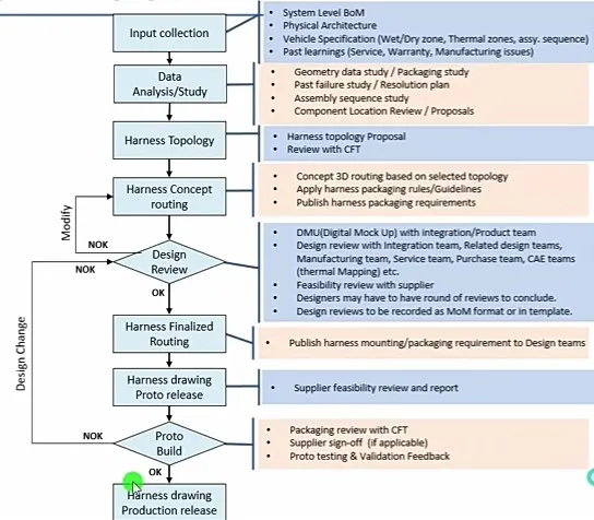
Harness Routing: Harness Routing basically shows the path of wiring harness into the vehicle. This is representation of the lay out of the wiring harness on the vehicle in geometrical way(3D).
Harness Packaging: Harness Packaging involves the decisions of harness mounting (Clips/Clamps) and routing management (Use of brackets, Channels, guiding devices) It is also deals with the clearance management, Aesthetic requirements, Thermal management, manufacturability etc.
 |
|
Figure 97: Routing and Packaging process. |
5.1 Design criteria for wiring harness
- Wiring harness should be routed in such a way that it is easy to assemble on vehicle. Wiring harness topology plays important role to meet these criteria.
- Wiring harness should be routed in a way that it is easy to access in case of service or failure analysis.
- Wiring harness should be secured properly so that it will not get damaged by surrounding component interaction.
- Wiring harness routing should be kept away from Heat Zones like Engine exhaust manifold, Muffler, Silencer, Turbo charger, EGR etc.,
- Wiring harness should be kept away from sharp environment like sheet metal bracket edges, corners, panel edges etc.,
- Ensure that any Human Machine Interactions (HMI) are not causing any damage to harness. Route it away from those areas or protect it properly. Ex. Possible damage in service or during testing/validation (air filters, tail gate openers).
- Wiring harness should be routed in or closed to driver and passenger reach zones like foot zones.
- Wiring harness should be routed away from hoses carrying high pressure fluids like hydraulic oil, brake oil, fuel. If it is routed along with hoses, then positive clamping should be used to ensure enough clearance maintained with hoses.
- Dynamic conditions of vehicle components should not damage wiring harness. Ensure that enough slack is provided to avoid the damage. Ex. Engine rocking during operation, Steering rotation, door hinges, door latches etc.,
- Keep harness away from the components which are subjected to movement during their normal operation like Engine timing belt, ABC pedals, Clutch lever and cables, Steering shaft, Parking brakes, door hinges, door latches etc.,
- Keep harness away from tyre envelope.
- Ensure that harness is not visible or exposed in vehicle. Harness dressing and aesthetic areas shall be taken if it is routed in visible areas.
- Easy accessibility and minimum work to access the service and diagnostic related features which are part of wiring harness supply. Ex. Diagnostic connector, Trailer sockets, Electrical Power Take outs (PTO) etc.
5.2 Packaging rules and best practices
- Wiring harness routing shall provide ease in manufacturing, accessibility, easy removal and easy maintenance of attached equipment and wiring harness.
- Routing through small structural holes and openings shall be avoided, to minimize chaffing and handling of the wiring harness during installation.
- Avoid the harness routing and clipping in blind zone of operator during harness assembly or in service.
- Routing shall offer the protection against possible damage through common misuse such as being handhold and temporary support for test equipment.
- Provide additional slack to the harness according to the surrounding and harness bending requirements. If harness is passing through the closures/doors or tail gates, then envelope dimension during opening and closing of doors shall be considered to provide the slack. Check the harness slack requirements with open and close conditions to avoid excess slack.
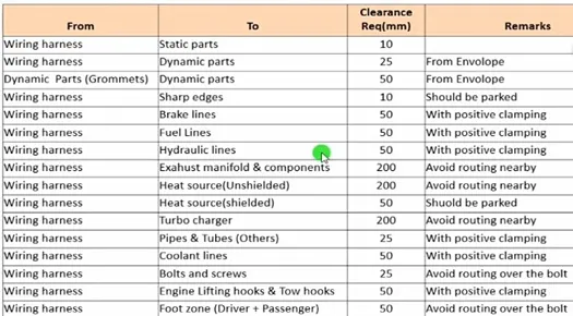
- Ensure that routing meets the clearance requirements with different surrounding parts as described in below table. Any deviation to these requirements shall be discussed and agreed between all stake holders before design releases. Necessary arrangement to protect the harness shall be made in this case.
 |
|
Figure 98: Clearance measurement. |
- Ensure that worst case envelope dimensions are considered for the dynamic assemblies to meet the desired clearance requirements with wiring harness bundles.
- Routing shall provide the enough slack for each branch to avoid additional stress on wires and terminal crimping joints but ensure that extra slack does not cause wiring harness fouling with surrounding parts and impact desired clearance requirements.
- Avoid the routing over the bolts, near the bolted joints or screwed joints. It may damage harness or may puncture the harness.
- Keep the harness away from the panel mounting screws or bolts.
- Avoid the harness routing near the sharp edges or over the sharp edges like thin sheet metal brackets, panel joints. If routing cannot be avoided in this area, then addition protection on the harness or on the surrounding shall be provided to avoid any damage.
- Ensure that wiring harness routing is routed at least 100mm away from ABC pedals, clutch lever and cables, engine timing belt or any other dynamic components. If it is not possible to achieve desired clearance, then arrangement of positive clamping with help of plastic channels or clamps to be made to ensure safety of harness.
- Enough clamps shall be providing to ensure the positive clearance with surrounding and safety of wiring harness. Distance between two clamps on a straight branch should be maximum 200 mm. However clamping requirements should be decided based on harness bending, surrounding and mounting requirements.
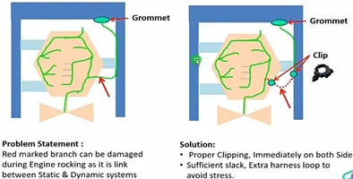
- If harness is routed between the dynamic and stationary assemblies, then ensure that fixed positive clamping is provided immediately at both end of assemblies. This is required to avoid harness damage in rocking conditions. Ex. Harness passing from engine to chassis. Positive clamping should be provided at engine and chassis at first connection point. This is to avoid harness damage when engine rocks.
- Harness branch should be secured with positive clamping if device connector fitment is not straight and demands for harness bending. Provide the clip of the same device if possible.
- Ensure that enough slack provided for the branch which connects dynamic assemblies with stationary assemblies. Dimension of buffer length should be decided based on envelope dimension of dynamic part in all worst-case situations. Ex. Harness passing from engine to chassis.
- Keep the harness away from engine heat generation components from exhaust manifold, turbo chargers, EGR components, heating lines etc.,
- Harness should be away from engine lifting hooks.
- Avoid direct support for harness on fuel lines routed in engine. It should be acceptable if it is provided with separator clamp and satisfy clearance requirements.
- Try to avoid use of too many sheet metals brackets on engine. Try to use the available threaded bosses on engine or demand for it. Too many brackets on engine may increase complexity for assembly.
- Keep the harness away from transmission dynamic assemblies like drive shaft or propeller shaft.
- Keep the harness away from clutch cables and lever mounted on transmission housing. If it is mounted near to these parts, then ensure the enough positive clearance achieved by fixed clamping.
- Use of rubber grommet is recommended if harness is passing through sheet metal panels. Ex. Firewall, passing to door, tailgate, to wheel arch etc.,
- Rubber grommets must be used if harness is subjected to vibrations or mechanical fatigue loads/movements. Ex. Harness connecting to wheel sensor which is fixed on axle. Axle is subjected to movements because of suspension. Vibration absorber grommets to be used to avoid any stress or damage on wire joints or connectors.
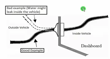
- Rubber grommets must be used if harness is passing from wet zone of vehicle to dry zone. Ensure that grommet is suitable to use as water ingress sealing devices and enough flat resting area is provided on mounting panel to ensure the sealing. Ex- Harness passing from Engine Bay to cabin through firewall.
- To protect the harness components and devices from water ingress, always keep wet zone side branch lower than the dry zone side branch. This is to ensure that the harness does not provide path for water entry through bundle. This rule is applicable for all grommets used as sealing devices.
 |
|
Figure 99: Grommet usage at wet zones. |
- Always keep the harness connector at height than harness routing and branching points. This is to ensure that gravity does not allow water entry through harness bundle.
- Use of plastic guiding channels are recommended to meet the clearances in critical areas if it is difficult to achieve by use of clamps. Ex- Inject harness routing on engine.
- Branch length should be minimum 50 mm.
- Minimum distance between clip and nearest branching point should be 25 mm.
- Minimum distance between two breakouts should be 50 mm.
- Limit the number of branches from single branching point to 4.
- If there are multiple branches routed from branching point for identical connectors, then connector connection Poka-Yoke should be achieved by harness dressing and managing lengths to avoid incorrect connections.
- Ensure that harness protection is provide according to surrounding temperature, manufacturability and expected reliability.
5.4 Guidelines for battery cables routing
- Battery cables are one of the critical wiring systems in the electrical distribution system.
- In most of the cases, battery cables connected to the starter motor during in-rush and load over the period of time.
- Special care must be taken to protect such a cable to avoid the mechanical damage to insulation which may results in short circuit. Short circuit of unprotected cables may result in vehicle burning case.
- Battery cable should be routed at least 50 mm away from the metallic surroundings.
- Ensure enough clippings are provided to secure the battery cables. Ensure the cables bending by providing clipping at both the ends.
- Avoid the unnecessary slacks in battery cables.
- Ensure that terminal orientation used at battery post and starter motor/alternator do not demand for extra bending of the harness or stress on the terminal joints for the decided cable routing. Terminal should be selected based on decided routing path.
- Use of grommets is must if battery cables are passing through holes over the panel edges.
- Appropriate protection to achieve desired temperature range and high abrasion resistance should be used for battery cables. Battery cables without protection devices should not be acceptable.
- Ensure that all ends of battery cables are protected by rubber boots. Rubber boots should be selected according to terminal size and profile.
- Clearance management basically focus on the wiring harness clearance with the surrounding parts.
- This is primary requirement for the routing and packaging.
- Clearance management should be conducted in CAD software or visualization software.
- It is also known as DMU (Digital Mock up).
- This study is part of geometrical integration.
- Clearance requirement varies between industry to industry. However, the requirements can be used to understand the basics of clearance management from Fig. 98.
- Ingress protection for wiring harness mainly deals with connector selection, routing direction and use of grommets.
- Vehicle dry zone and wet zones information is must before you decide the mechanism. Typically, the engine bay is wet zone and cabin area is dry zones. It is required to identify for doors because door seals create the boundaries.
- Do consider the washing jet pressure standard for the market.
- Connection Selection:
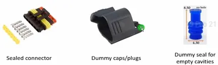
- Selection of sealed connectors (IP rating) for wet zones and unsealed connectors for dry zones.
- Use the sealed dummy plugs for all unused/package protected connectors.
- Use dummy seals for unused cavities in connectors.
 |
|
Figure 100: Connector sealing. |
- Routing Direction:
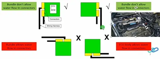
- Ensure that wiring harness bundles not allowing water to flow to the harness connectors or to the grommets. Following care must be taken:
- Keep the wiring harness connectors at height than the harness clipping point. Same point is applicable for grommets as well.
 |
|
Figure 101: Water ingress protection. |
- Drip Loop Creation:
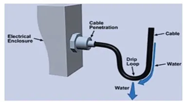
- Formation of Drip Loop has always been a concern which leads to short circuit. Drip loop is a phenomenon where it allows the water to drip and enter the connector cavities or modules.
- When water enters the module or connector cavities, it becomes a major cause for short circuit. Also, if the water gets accumulated inside the tubing because of the drip loop. Wire soaking happens, leading to high chance for short circuit.
 |
|
Figure 102: Drip loop. |
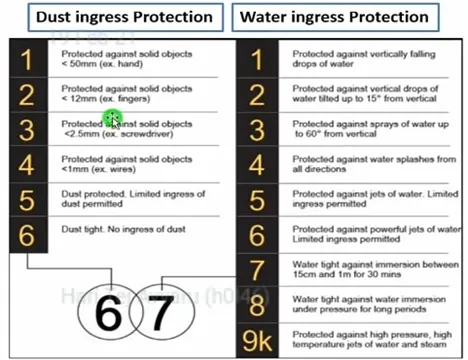
- IP Rating – Ingress Protection Rating:
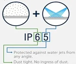
- IP ratings are defined in international standard EN 60529 (British BS EN 60529:1992, European IEC 60509:1989). They are used to define levels of sealing effectiveness of electrical enclosures against intrusion from foreign bodies (tools, dirt etc) and moisture.
- IP rating is defined in following fashion. Two digits are used to indicate the resistance capability to dust ingress and water ingress respectively.
 |
|
Figure 103: IP rating. |
 |
|
Figure 104: IP ratings. |
5.7 Thermal Protection Management
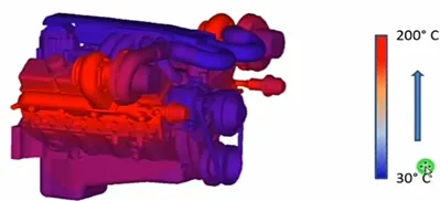
There are two aspects in this topic. First is the harness routing management in the high temperature zone and second is the wiring harness protection int eh high temperature zone. Primary input required to decide the routing path and thermal protection is “Thermal Mapping Data” of the vehicle. Skin temperature data of some hoses are also required if harness is routed nearby to them (coolant hose).
 |
|
Figure 105: Thermal mapping data of engine. |
Following means can be used to protect the wiring harness in high temperature zones:
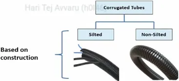
- Use of Corrugated tubes:
- Corrugated flexible tubes also known as Cot tubes / Convoluted Conduits have a wide range of application in automotive industries.
- Corrugated tubes are made from plastic material and they are flexible.
- Selection of corrugated tubes are mainly driven by wiring harness bundle diameter and temperature resistance requirements.
- Black colour tubes are widely used in Automotive and off-road applications but other colours also used to highlight the critical harness for ex. Emission system harness.
 |
|
Figure 106: Types of corrugated tubes – Based on construction. |
 |
|
Figure 107: Types of corrugated tubes – Material and Temperature resistance. |
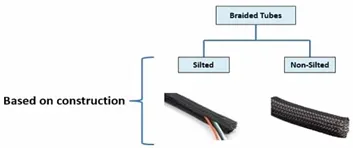
2.Use of Braided tubes (Nylon woven loom) and Silica sleeves –
- In case corrugated tube is not suitable for the very high temperature zones (Specially in Exhaust area), use of breaded tubes and silica sleeves.
 |
|
Figure 108: Types of Breaded tubes. |
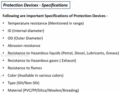
- Specifications:
- Temperature resistance (mentioned in range)
- Bundle diameter
- Abrasion resistance
- Resistance to Hazardous liquids (Petrol, Diesel, Lubricants, grease)
- Resistance to Hazardous gases (Exhaust)
- Resistance to flames
- Color
 |
|
Figure 109: Types of braided tubes – Based on construction. |
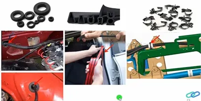
Chaffing is nothing but wiring harness damage due to contact with metallic sharp edges or by any other mechanical means. There is very simple technique to avoid these types of failure
- Clearance management keep harness away from surrounding parts. Specially away from sharp sheet metal edges.
- Use of sufficient and appropriate harness clips. Fix the harness bundle in the areas where it can get in contact with sharp edges. This is the full proof way to avoid the damage.
- Convert the sharp edges into smooth surface by applying rubber beading on it. Not recommended and should be used if above two methods are not feasible.
- Use of rubber grommets whenever sharp edge is created due to through holes. Moulded rubber beading is also available to protect round or oval hole edges.
 |
|
Figure 110: Chaffing protection. |
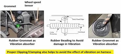
- Routing near sharp edge is one of the major risk factors, which contributes to the rupture of wire harness.
- Many times, we forget to take the dynamic conditions and sharp edges into consideration, especially when the harness is mounted on a vibrating object. We can also consider taking an alternate routing path to avoid sharp edges or we can use edge protectors like edge trims, rubber sleeves, Grommets etc.,
- Also, wiring shall not be routed near screws which can puncture the wiring.
- Recommended solution is to keep harness away from this area if possible.
- Typical ex. Of this type of situation is ABS wheel speed sensor cable routing. Wheel speed sensors are mounted on wheel hub and cable is routed through shock absorbers which are quite dynamic in operation and creates lot of vibration with high amplitude.
 |
|
Figure 111: Vibration protection. |
5.10 Routing on/near Dynamic parts (Engine, Wheel)
- This situation is taken in discussion to explain the applicable conditions when aharness is routed from dynamic parts to station parts. Wheel speed sensors cable example is explained in previous section.
- Another common ex. is of harness routed for engine components which eventually come from vehicle body or chassis.
- Engine is always mounted on rubber mounts which should be do the job of shock absorption because engine vibrates a lot during its operation.
- These vibrations are killed at rubber mounts so that they won’t get transfer to vehicle systems.
- Highest amplitude of engine vibration is occurred during cranking or at idle RPM (Low RPM). This is called as Engine Rocking.
 |
|
Figure 112: Routing near dynamic parts. |
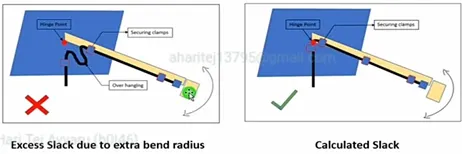
Harness bend radius is another important aspect to keep in mind. Bending may be possible in virtual routing but on vehicle it won’t go as shown in 3D. Consider the following points while defining bending radius of harness –
- Bundle diameter
- Type of covering used
- Type of wires used in bundle (insulated thickness does matter)
For silted cot tubes it is recommended to use bend radius minimum 2 times of bundle diameter. However minimum bend radius for different cot tubes sizes can be confirmed with supplier.
Shielded cables (CAN/Sensor), Battery cables (with thicker insulation).
On other hand, excess bend radius shall not turn into excess harness length of wiring harness. This can lead to the fouling with surrounding components and then mechanical damage. Special cares shall be taken for battery cables as discuss in earlier session.
 |
|
Figure 113: Harness bending. |
5.12 Interconnection connector management
- Whenever there are two or more wiring harness connected to each other, electrical and mechanical joints formed by connectors and called as interconnection. Such a connectors are also called as interconnection connectors or inline connectors.
- Device connectors are always parked with device body. They don’t need addition parking provision.
- However, situation of interconnection connectors are not similar to device connectors.
- Interconnection connectors are not parked with any devices but should be pared with the help of clips/clamps/sheet metal brackets, Plastic brackets etc possible to the packaging conditions
- Un parked connectors can create:
- Rattling noise
- Physical damage to connectors
- Uncontrolled harness routing
- Manual errors during assembly because undefined paring.
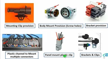 |
|
Figure 114: Connector’s parking positions. |
- Sometimes use of foam on connectors gives some relaxation from rattling noise and to protect connectors from physical damage.
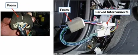 |
|
Figure 115: Foam usage. |
6 WIRING HARNESS ROUTING OF ENGINE
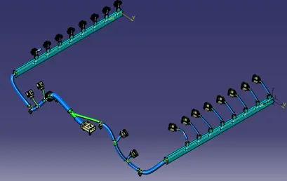
The Bugatti v6 engine is taken to route the wiring harness. The engine modeller will provide the dummy connectors at all the locations. First check for all the connector and sensor locations. The present engine has 8 connector location on each side and 2 sensors at each side. The clips, clamps and channels can be used to route the harness with optimal solution.
Note: The components which are connecting to the engine are not part of the geometrical bundle assembly they are going to be part of the context assembly even though they are electrical components.
Step 1: create a new product file and rename it as Assy_Engine_Wiring_Harness_Context
 |
|
Figure 116: Assy_Engine_Wiring_Harness_Context. |
Step 2: Now copy and paste the Engine assembly file to the context assembly.
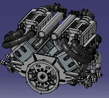 |
|
Figure 117: Bugati_Engine. |
Step 3: Create a new product under context assembly and rename it Assy_Engine_Harness_Geometrical_Bundle.
Step 4: Import all the required connectors with electrical properties into the Geometrical bundle.
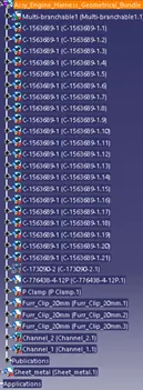 |
|
Figure 118: Connector components in Geometrical bundle assembly. |
Step 5: Place all the connectors in the specified locations of the engine using snap tools.
Step 6: After placing all the connectors, it is required to locate the interconnection connector.
Note: It is advised to use already drilled bolts for placing the interconnection connector and not to drill any holes to the engine exhaust manifold as it leads to damage of the engine.
Step 7: Add sheet metal bracket into the context assembly for interconnector support.
 |
|
Figure 119: Sheet metal bracket. |
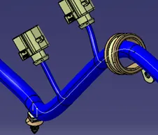
Step 8: Add p-clamps to the context assembly and not to the geometrical bundle assembly because they are fixed at the manufacturing line. If p-clamps are supplied with the wiring harness then it can be part of geometrical bundle assembly.
 |
|
Figure 120: P-clamp and fir-tree. |
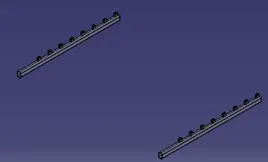
Step 9: Channels can be imported into the wiring harness but a study has to be done on the placement of channel in the correct location without having any extra cut outs and they should be fouling. Define the channel as equipment instead of support. Give all the bundle connection points correctly.
 |
|
Figure 121: Channels. |
Step 10: Now switch to Electrical harness assembly design and select the geometrical bundle command and select the Assy_Engine_Harness_Geometrical_Bundle. The icon of the assembly converts to bundle.
Step 11: Start the routing. Start from the interconnection connector.
Step 12: Considering all the harness packaging rules, the harness for the engine is routed.
 |
|
Figure 122: Wiring Harness Routing. |
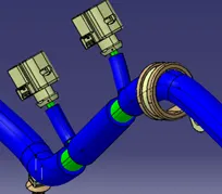
Step 13: Add corrugated tubes for the bundles.
 |
|
Figure 123: COT tubes. |
Step 14: Check for bundle continuity. All the bundles are fully connected.
 |
|
Figure 124: Bundle connectivity check. |
Step 15: Create CAT part for the geometrical bundle assembly.
 |
|
Figure 125: Geometrical Bundle AllCATPart. |
Step 16: Measure the geometrical bundle length using measuring tools. The total length of the bundle is 3955 mm, approximately 4 m.
 |
|
Figure 126: Bundle length measurement. |
Step 17: Create the electrical flattening of the geometrical bundle assembly.
 |
|
Figure 127: Engine harness flattening. |
Step 18: Create the 2D drawing file with all the details.
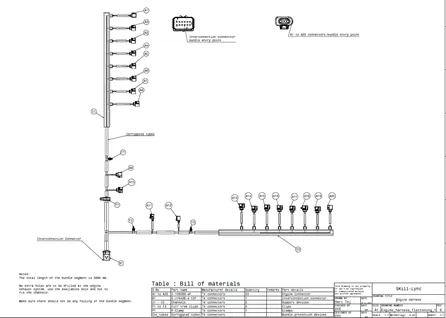 |
|
Figure 128: Engine harness 2D drawing. |
- The wiring harness basics and the industrial practices are studied.
- Different connectors and their installation in 3D modeling are practiced.
- The protective devices and their application at the required region in the wiring harness bundle are practiced.
- Electrical workbenches in CATIA V5 such as electrical part design, electrical assembly design, electrical assembly harness, electrical harness flattening are exercised.
- 3D representation and 2D drawing of the engine harness are implemented.
- Engine harness is taken as a case study and developed the geometrical bundle assembly without fouling the bundle segments.