Project 1 Designing a battery pack for EV of roughly 150kW with 120 V.
Q1)
Aim: Designing a battery pack for a car of roughly 150 kW with 120 V.
Lets, Use cells 3500 mAh 3.6V nominal NMC chemistry cells in the battery pack
Power of the Car= 150kW
The required voltage(rated voltage) of the car = 120V
--NMC Chemistry cells,
nominal voltage = 3.6V
cell capacity = 3500 mAh =3.5Ah
max. voltage of the cell =4.2V
`"Motor Current" =("Power of Motor")/("Motor Voltage")`
`= (150*1000 W)/(120V)`
`=1250A`
a) Step1: Designing the battery pack configuration
Cells in Series:
`"Number of cells in series connection" = "Rated motor voltage"/"Cell nominal Voltage"`
= `(120V)/(3.6)`
`= 33.3`
Due to decimal numbers, we need to consider possible values one case is to round off to a lower value to that number and another case to the nearest higher number. the numbers will be 33 & 34. To select one value among these two, we need to follow a set of steps.
case1
Considering, the number of cells in a series is 33
nominal battery voltage = no.of cells in series x nominal cell voltage
`= 33*3.6`
`=118.8`
case2
Considering, the number of cells in a series is 34
nominal battery voltage = no.of cells in series x nominal cell voltage
`= 34*3.6`
`=122.4`
From, both cases we will select case 2 (34cells) because it is always better to have more nominal battery voltage than the required motor voltage(car required voltage).
Cells in parallel:
`"Number of cells in parallel connection" = "Motor continuous current"/"Nominal cell capacity"`
`= (1250)/(3.5)`
`=357.14`
Due to decimal numbers, we need to consider possible values one case is to round off to a lower value to that number and another case to the nearest higher number. the numbers will be 357 & 358. To select one value among these two, we need to follow a set of steps.
case1
Considering, the number of cells in a parallel is 357
`"Total Battery Capacity" = "Number of cells"*"Nominal cell capacity"`
`= 357*(3.5Ah)`
`=1249.5Ah`
case2
Considering, the number of cells in a parallel is 358
`"Total Battery Capacity" = "Number of cells"*"Nominal cell capacity"`
`= 358*(3.5Ah)`
`=1253Ah`
- From, both cases we will select case 2 (358 cells).
- We are always required to discharge at a 1C rate, and the continuous current requirement is 1250Ah, it is always recommended to consider the battery that has higher capacity than the motor current requirement.
>The Battery pack configuration for a car of 150 kW with 120 V is 34S358P.
The required battery pack configuration 34S358P can be split into four modules with 2x18S90P and 2x16S89P. The Figure 1 depicts the battery pack configuration of 34S358P.
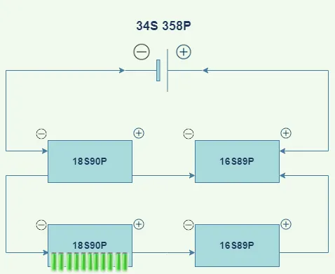
Figure 1
b)Battery Management System Topology:
This battery pack has 34cells series, generally, for electrical vehicles, Master & Slave topology is used. And we choose master & slave topology for this battery pack because both master-slave and modular topologies satisfy the no.of cells condition but when it comes to implementation, the complexity of the master-slave topology is better. Another reason for selecting master-slave topology is its scalability.
Let's consider a flow diagram for better understanding.
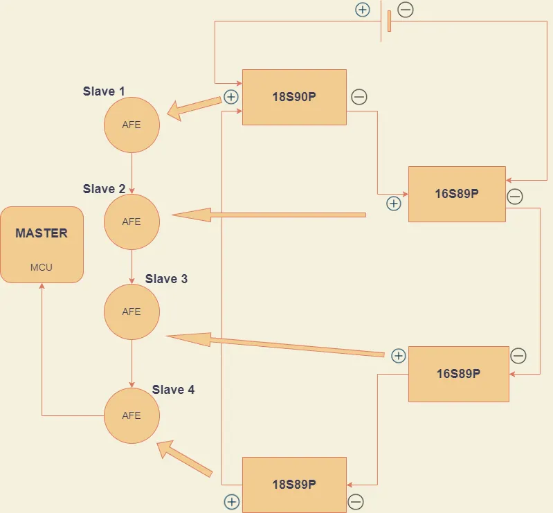
Figure 2
Figure 2 illustrates the Master and slave BMS topology for the Battery pack with 34S358P Configuration. In this BMS topology, we are using four slaves(AFE) and one Master. The slave1 receives cell data from module 1 and then sends it to slave2, then slave2 receives cell data from module 2 and then sends the module 1 and module 2 data to slave3 and soon. Lastly, slave 4 sends all the received data from module 1,2,3,4 to the Master(MCU). Further, the MCU process the data.
Q2)
Aim: Building a 3S2P battery pack configuration with a generic battery block using Matlab/Simulink.
For constructing a battery pack configuration we need to consider the cell chemistry and type of cells that can be used.
Let's consider the cylindrical-shaped Lithium-ion batteries from Samsung.
Model: Samsung 18650 25R 2500mAh 3.6V
Nominal Voltage = 3.7V
Mini. voltage = 2.7V
Max. Voltage = 4.2V
The total number of cells used in 3S2P is three cells connected in series for two times in parallel connections.
`"Total no. of cells" = "Total no.of cells in series"*"Total no.of cells in parallel"`
`= 3*2 = 6 cells`
The below diagram depicts the 3S2P connection of Samsung 18560 cells.

The generic battery used in this Simulink design is shown below.
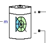
Figure 3
After importing the battery model, we need to set the attributes for the battery. The attributes are similar to that of the model(Samsung 18560) that has been selected.
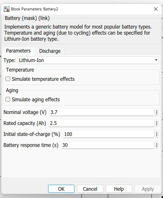
Figure 4
After setting attributes we need to connect the 6 cells in three series and two parallel connections like shown in Figure 5.
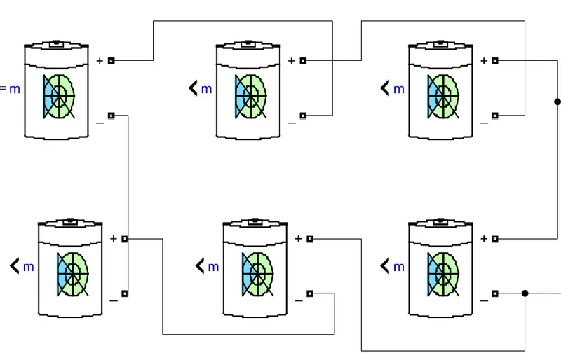
Figure 5
A bus selector is used for SOC and Voltage.
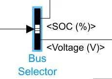
Figure 6
From displaying the values of SOC, voltage and current we use a display.
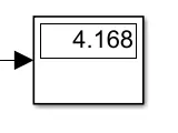
Figure 7
For plotting the values we use a scope.
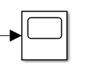
After assembling all these systems we will get an circuit.
Simulation Design:
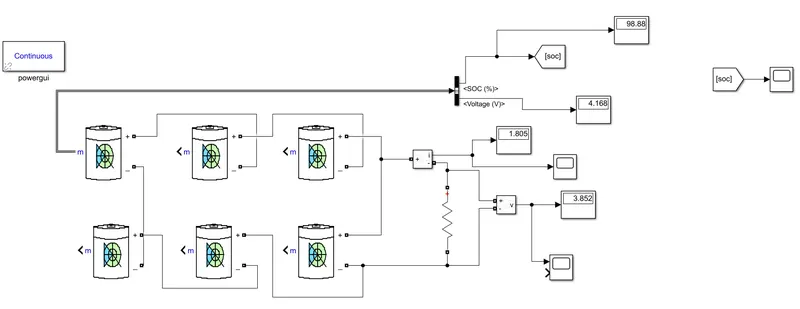
Figure8
Procedure:
The given battery pack configuration 3S2P .
The cell specifications of
Nominal Voltage = 3.7V
capacity = 2.5Ah
The total voltage of the battery is 3x3.7V is 11.1V
The total capacity of the battery is 2x2.6Ah is 5Ah
The initial SOC is 0%.
3 cells are connected in series for 2 times in parallel.
The C rate is taken as 1C, simultaneously the Simulink run time will be 1hr(3600s).
Further, we used a resistor in between the network to see parameter changes in the network.
The resistance= total voltage/total capacity
= 11.1/5
= 2.2Ohms
Now run the simulation model to see the simulation.
>Simulation results:
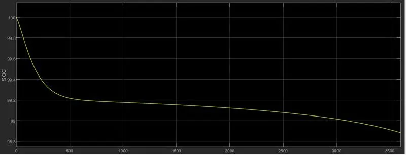
Figure show change in SOC for 3600sec runtime.
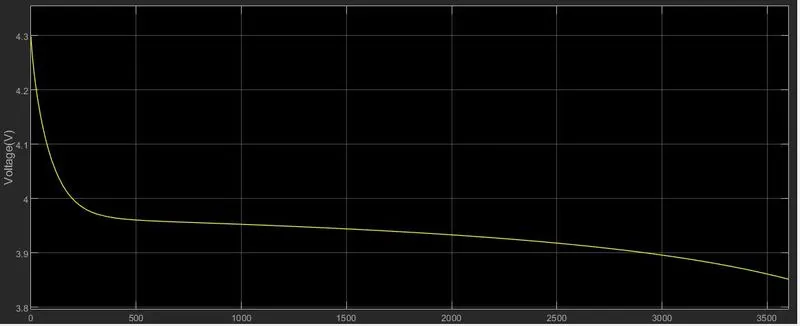
Figure shows voltage
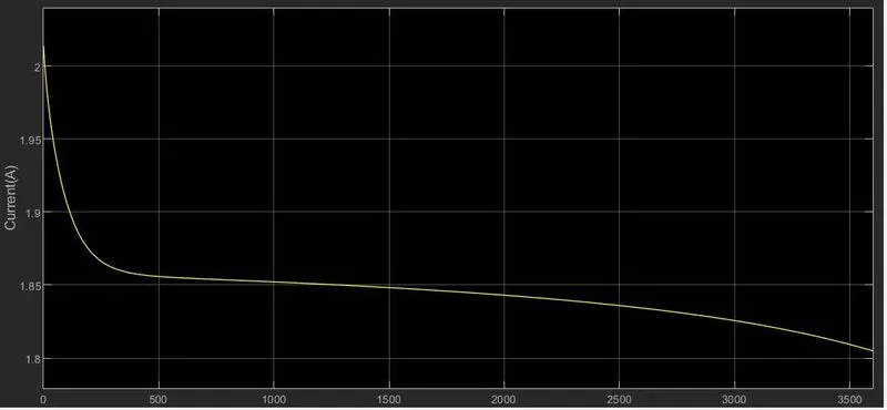
Figure show the current.
Conclusion:
We have designed the Battery pack Configuration for 150kW with 120V EV.
Selected suitable BMS Topology with reasons why selected and further sketched the BMS topology.
Lastly, simulated a battery pack with 3S2P configuration(Samsung 18650 25R 2500mAh 3.6V).