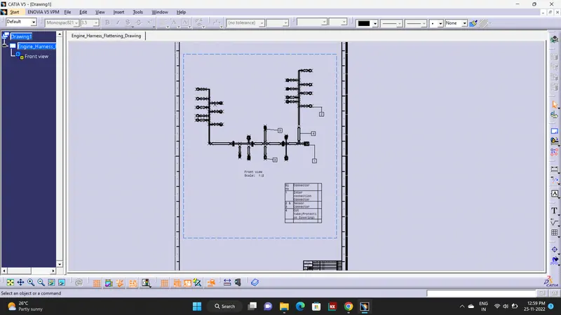
Project 1
Title: Engine Wire Harness Routing in CATIA V5
Objective:
To route the wiring harness on given Engine and prepare the flatten view drawing in CATIA V5.
Introduction:
An engine wiring harness is an organized set of wires, cables, connectors and terminals that controls a vehicle’s electrical system. Engine wire harnesses relay electrical power and control information to outlying components such as: Alternators, Audio Systems, Batteries, Blower Motors, Computers, Fuel Injectors, Fuses, Windshield Wipers and everything else that is controlled electrically that can be found in a vehicle.
Specifications:
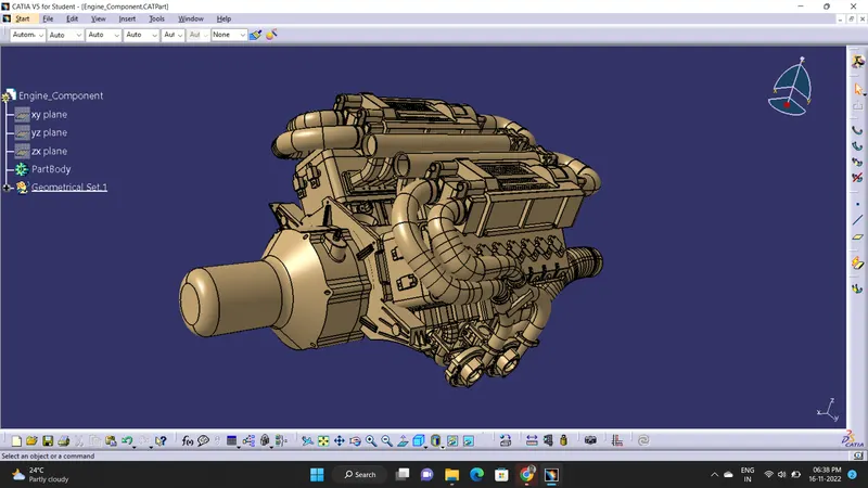
1) Engine:
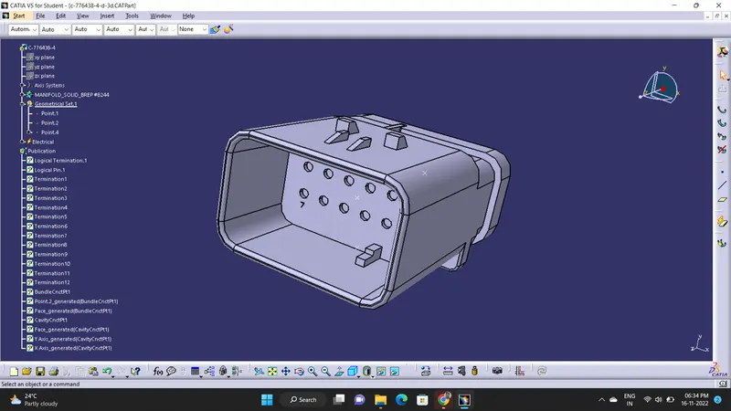
2) Connector 1:
3) Connector 2:
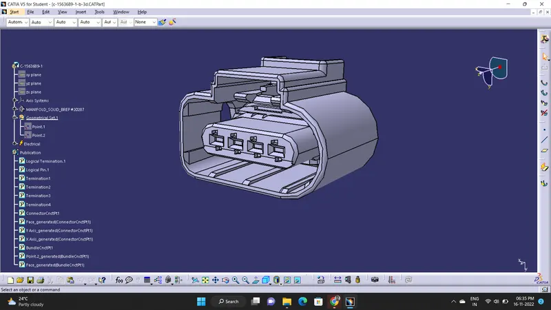
3) Connector 3:
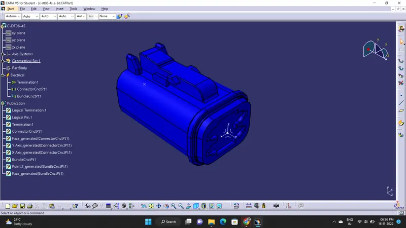
4) Guiding Channel Top:
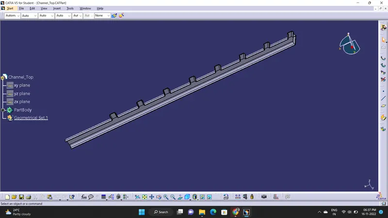
5) Guiding Channel Bottom:
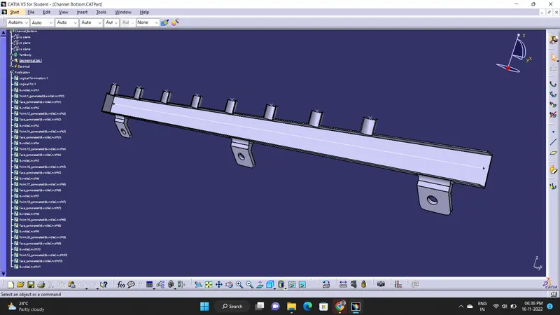
6) Fir Tree Type Mounting Clip:
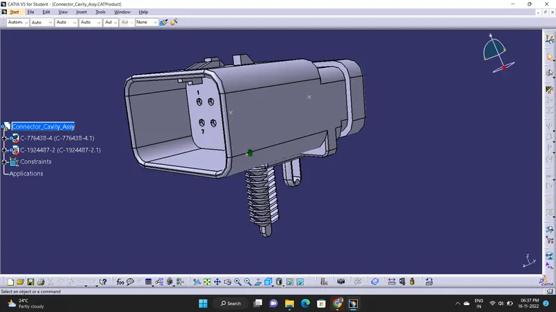
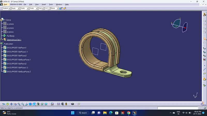
7) P Clamp:
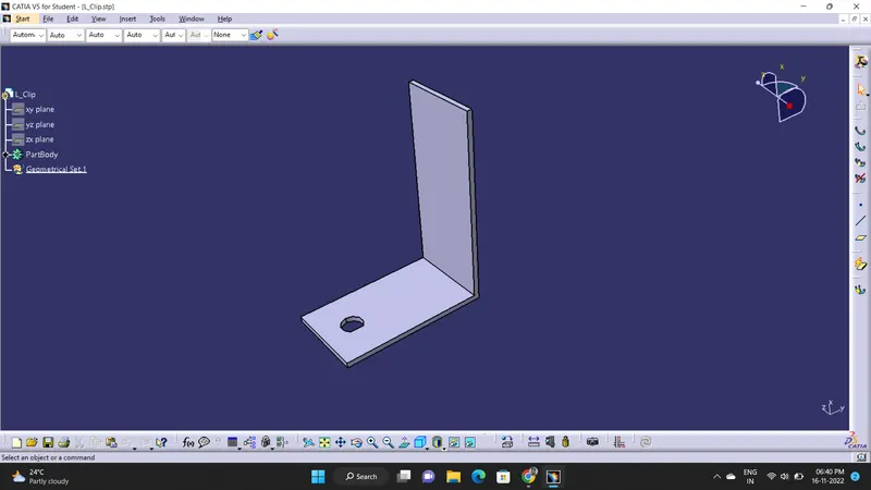
8) L Clip:
Definitions:
- Engine:
a. The CAD model is downloaded in .igs/.stp file format and converted into .CATPart format. - Connectors:
a. The CAD model is downloaded in .igs/.stp file format and converted into .CATPart format.
b. The connectors are defined electrically in the Electrical Part Design Workbench and the Connector, Bundle and Cavity Connection points are added. - Guiding Channel:
a. The CAD model is downloaded in .igs/.stp file format and converted into .CATPart format.
b. The guiding channel is defined electrically as an equipment and then bundle connection points are given to all of its entry and exit points. - Fir Tree Clip:
a. The CAD model is downloaded in .igs/.stp file format and converted into .CATPart format.
b. The fir tree clip is defined electrically as an mounting equipment and a cavity definition is given in its mounting contact face. - P Clamp:
a. The CAD model is downloaded in .igs/.stp file format and converted into .CATPart format.
b. The p clamp is defined electrically as a support and its entry and exit connection sides are given accordingly. - L Clip:
a. The CAD model is downloaded in .igs/.stp file format and converted into .CATPart format.
Design Methodology:
Wire Harness Routing:
a. Start the Assembly Design Workbench in Catia.
b. Bring in the Engine model and the Connectors along with all the other equipment into the assembly.
c. Snap connectors 1 and 2 into the given respective connectors mating ports on the engine.
d. Snap the main Interconnector into a L Clamp and fix it with a fir tree type mounting clip.
e. Snap the guiding channel and the P clamps in their appropriate positions.
f. Now start the Electrical Harness Assembly Workbench and convert the assembly model into an electrical assembly model using the Geometrical Bundle option.
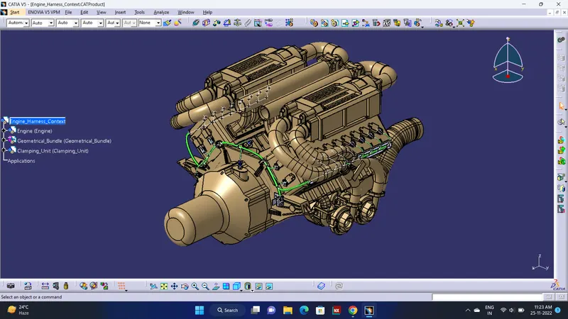
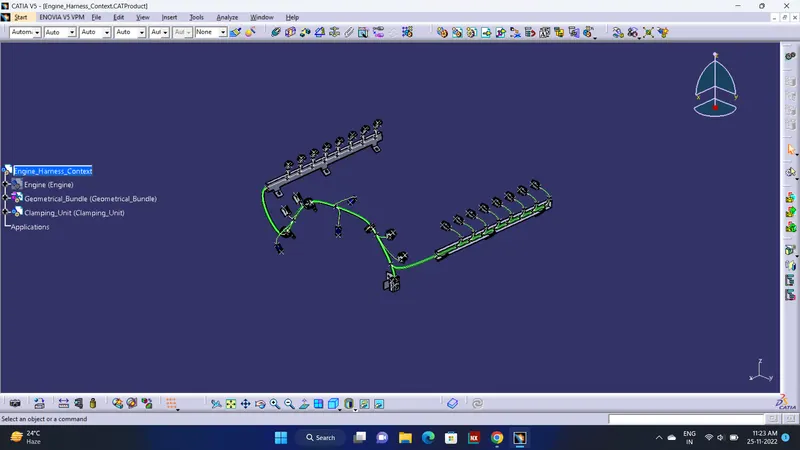
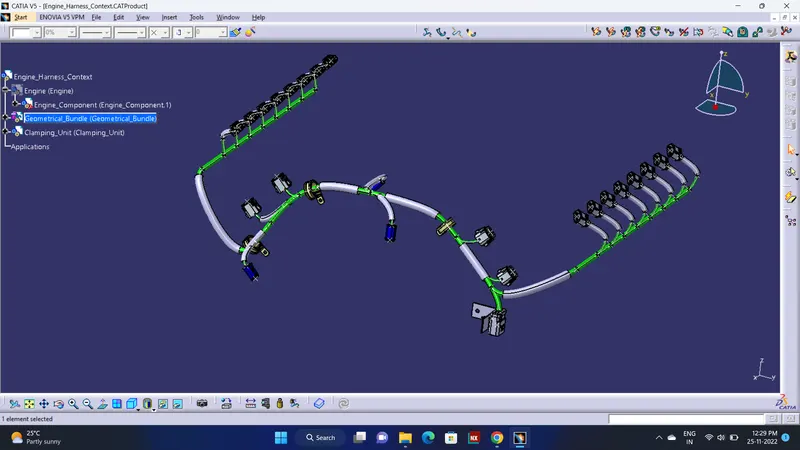
g. After that we start the routing of the main bundle from the main interconnector across the engine surface and route all the connectors from different bundle points of the main branch as shown in the figure.
Connectivity Checking:
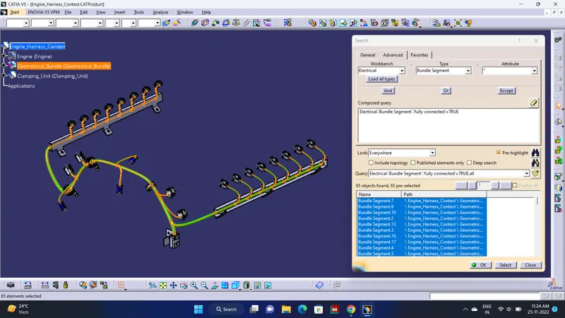
Make sure that selecting 'Single line' for bundle segment and 'Double' line for protective covering.
Wire Harness Flattening:
a.Create a new product file in Catia.
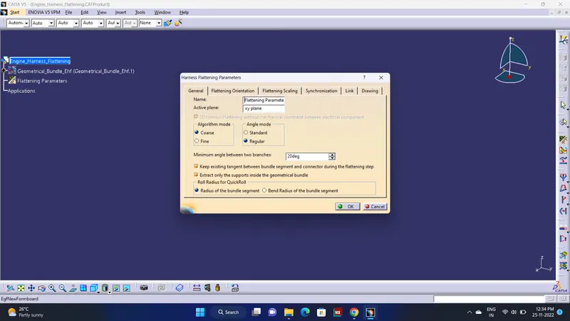
b. Start the Electrical Harness Flattening Workbench and select the Harness Flattening Parameters option from the toolbars.
c. A Harness Flattening Parameters dialog-box will appear and we have to set out our required parameters.
Again Check Connectivity:
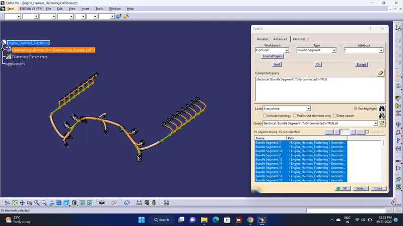
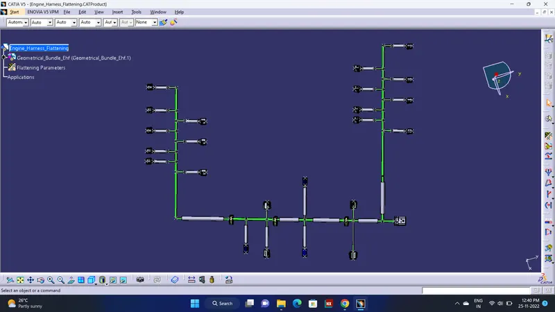
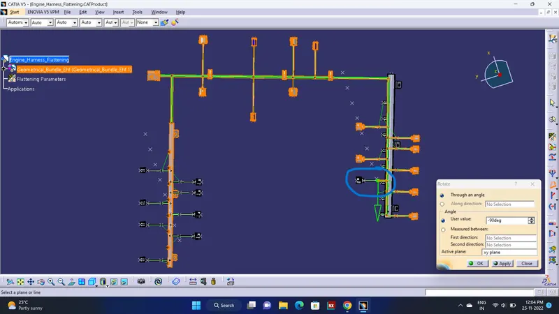
(i am faced thiss error when i triesd to rotate sub single branch its automaticaly selected all branches, so i keep it this only)
Creating a flatten view drawing for the wiring harness assembly: