Preparing Schedule & Cost Estimation for a building using REVIT
Question 1) Use the shortcut keys in Revit discussed in class to complete the following tasks and list them below
a. Using 3D model create a section box
b. To create similar doors and windows in a floor plan layout
c. To reduce the thickness of lines visible in plan views
d. To apply override settings to a floor in the model section view
e. To increase the range of visibility in a plan view
f. To select the previously selected items
g. To add annotations to the model views
h. To bring the model elements in line
i. To rotate the model elements
j. To move an object to another location
k. To copy a model element
l. To mirror an element about an axis
m. To create an array of model elements
AIM: To use the shortcut keys in Revit.
INTRODUCTION: Revit structure allows us to work on the revit software using the shortcut keys which makes our life and work much easier. Here in this section we will be able to understand the various shortcut keys for the different commands. These shortcut keys are given below.
a. Using 3D model create a section box.
- We can create a 3D model just by typing BX.
- So the shortcut key for creating the 3D is BX.
- To create the 3D model by using the shortcut key we need to select the element,which we required in 3D and just type BX. The 3D model has been created as shown in the below figure:
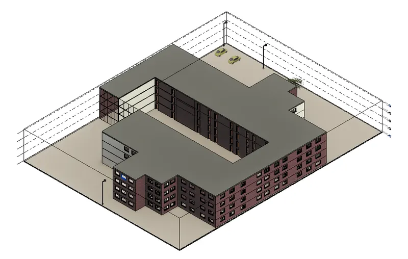
-The above 3D have been created by using the shortcut key.
b. To create similar doors and windows in a floor plan layout
- Similary we can create similar doors and windows in a floor plan layout by using the shortcut key.
- The shortcut key to create the similar doors and windows in a floor plan layout is CS.
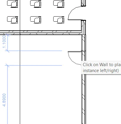
- So in order to create the similar doors and windows in a floor plan layout just type CS and then the similar doors and the windows has been created as shown in the below image:
DOOR:
WINDOW:
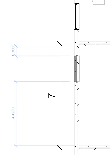
- These door and window has been created by using the shortcut key.
c. To reduce the thickness of lines visible in plan views
- We can reduce the thickness of lines visible in plan views by using the shortcut key.
- The shortcut key for reducing the thickness of lines visible in plan views is TL.
- We can reduce the thickness of lines visible in plan views just click on the line which we want to reduce the thickness and observe the thickness of that line and then just type TL and then the thickness of that line change as we use the shortcut key. As shown in the below figure:
- In the image below the line is thinner.
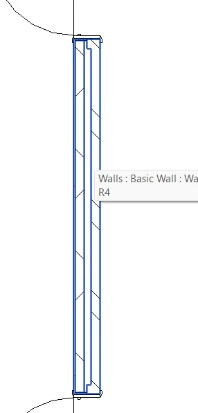
- In the below image after applying the shortcut key TL the thickness of the line increases.
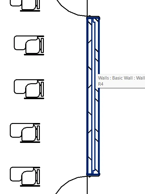
- Similarly we can reduce the thickness also just do it vice-versa. Then the thickness has been reduced.
d. To apply override settings to a floor in the model section view
- We can apply the override settings to a floor in the model section view by using the shortcut key.
- The shortcut key to override settings to a floor in the model section view is VG.
- To apply the override settings to the floor in the model section view just type VG a new dialouge box opens as shown in the below figure:
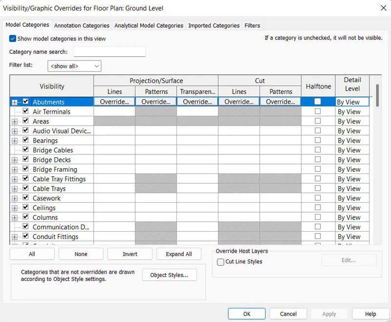
- In this search for the floor option and select the desired option which we want to change as shown in the below figure:
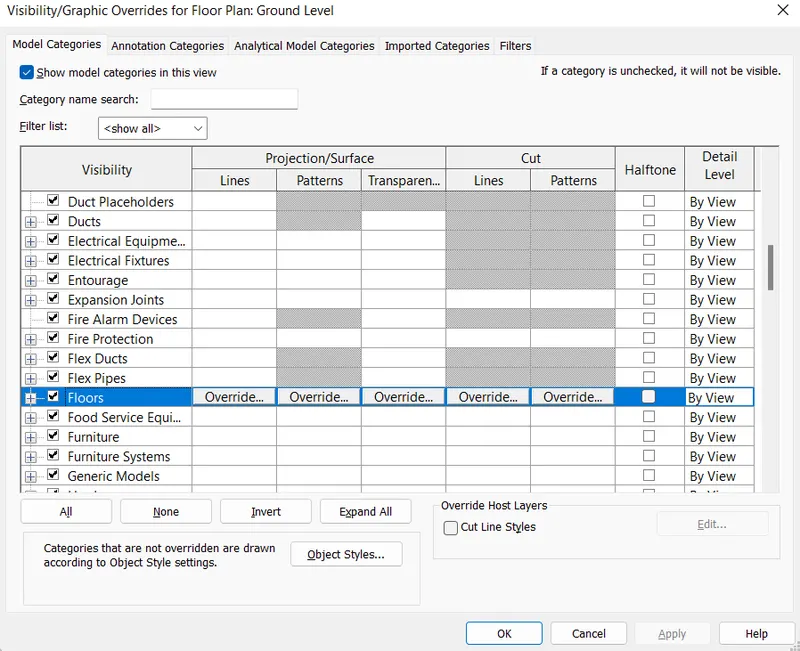
- This is how it will work using the shortcut key.
e. To increase the range of visibility in a plan view
- We can increase the range of visibility in plan view using the shortcut key.
- The shortcut key for increasing the visibility in plan view is VR.
- We can increase the range of visibility in a plan view just type VR and then a new dialouge box appears on the screen as shown in the below figure:
\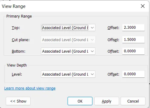
- Here we can change the different properties using this shortcut key.
f. To select the previously selected items
- We can select the previously selected items using the shortcut key.
- The shortcut key for selecting the previously selected items is Ctrl+Left Arrow Key.
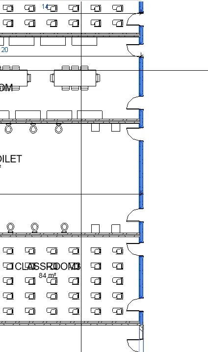
- We can select the previously selected items just by pressing the Ctrl+Left Arrow Key,by pressing them the previously selected items are selected as shown in the below figure:
g. To add annotations to the model views
- We can add the annotations to the model view by using the shortcut key.
- The shortcut key to add the annotations to the model views is DI.
- To add the annotations in the model view just type DI and then we can add the annotation in the model view as shown in the below figure:
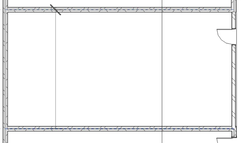
- This is how we can add the annotations in the model view.
h. To bring the model elements in line
- We can bring the model elements in line by using the shortcut key.
- The shortcut key to bring the model elements in line is AL.
- To align the model elements using the shortcut key just type AL and the align the elements as shown in the below figure:
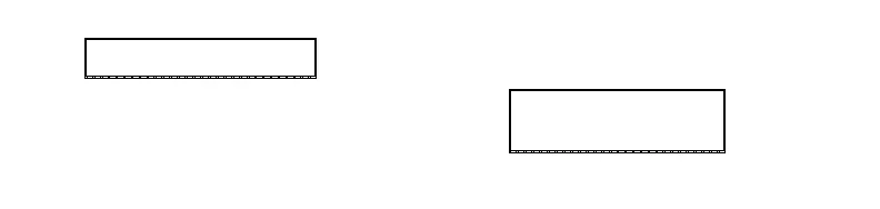
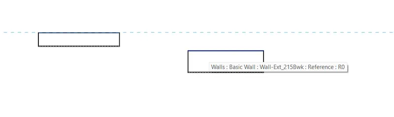
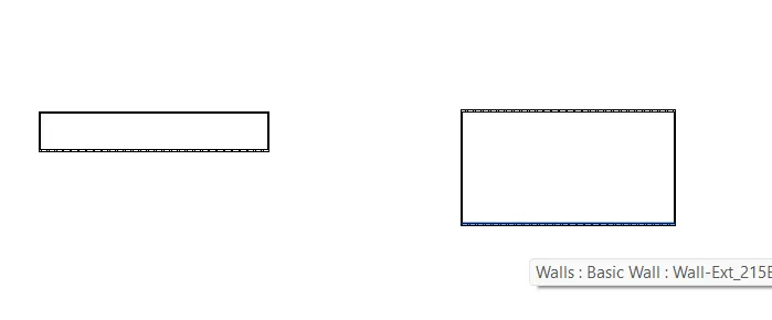
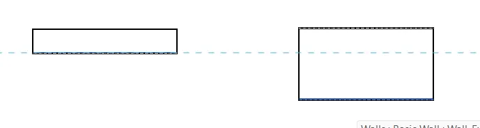
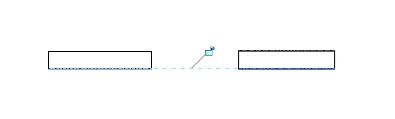
- This is how we can align the elements using the shortcut key.
i. To rotate the model elements
- We can rotate the model elements using the shortcut key.
- The shortcut key to rotate the model elements is RO.
- To rotate the model element just select the element and then type RO and then the element is rotated as shown in the below figure:
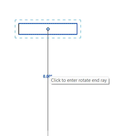
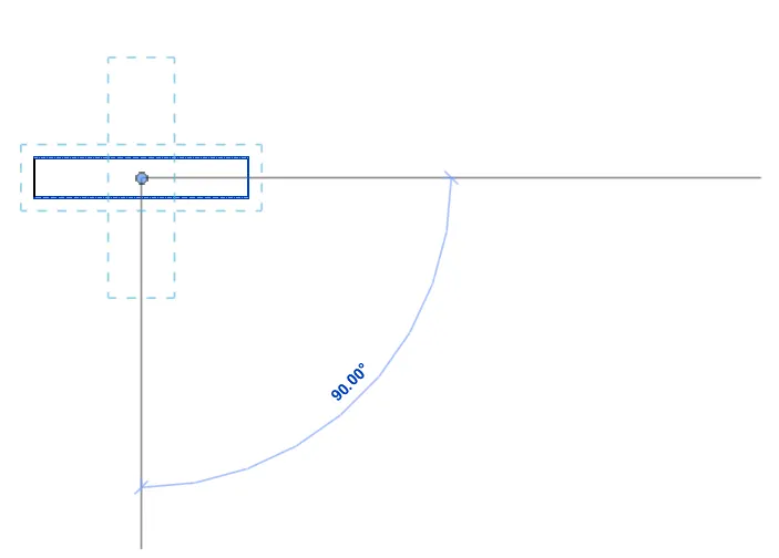
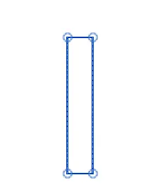
- In this we can rotate the model elements in any direction using the Shortcut Key.
j. To move an object to another location
- We can move an object to another location by using the shortcut key.
- The shortcut key to move an object to another location is MV.
- To move an object to another location just select the object and type MV and then move the object at the desired locations as shown in the below image:
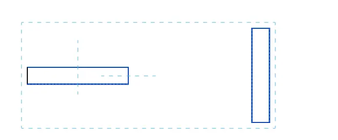
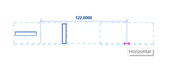
- The objects have been moved to the another location using the shortcut key.
k. To copy a model element
- We can copy the model element using the shortcut key.
- The shortcut key to copy the model element is CO.
- We can copy the model element by using the shortcut key just select the model element and then type CO and the object has been copied as shown in the below figure:
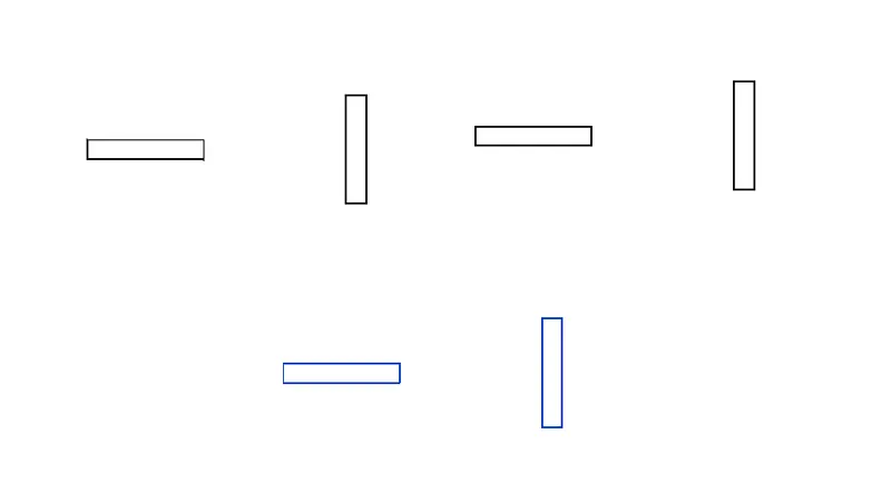
- The objects have been copied multiple times using the shortcut keys.
l. To mirror an element about an axis
- We can mirror the element about an axis using the shortcut key.
- The shortcut key to mirror the element about an axis is MM.
- To mirror an element about an axis just select the model element and type MM and the object is mirrored along its axis as shown in the below figure:
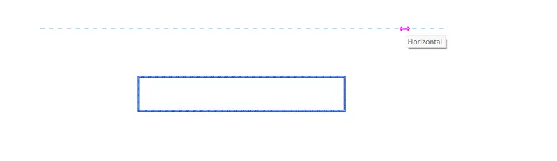
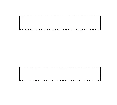
- This is how we can use the mirror shortcut key.
m. To create an array of model elements
- We can create an array of model elements by using the short cut key.
- The shortcut key to create an array model elements is AR.
- We can create an array of the model elements using the shortcut key just select the model element and then just type AR. Then we will be able to create an array of the model element as shown in the below figure:
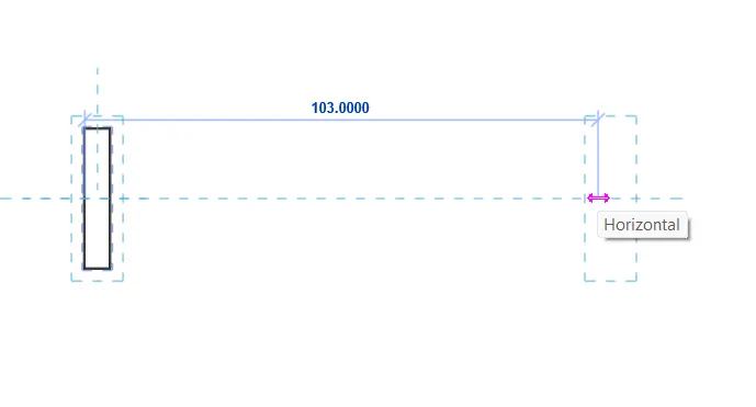
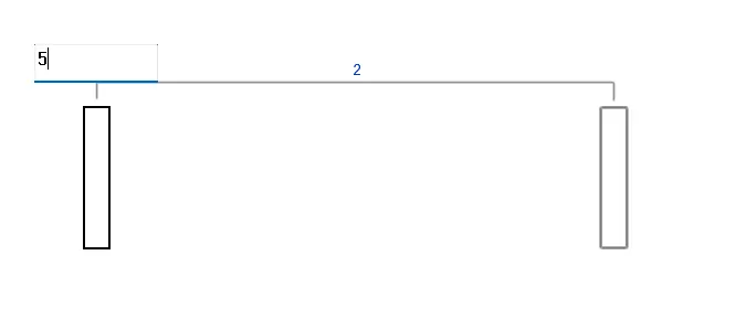
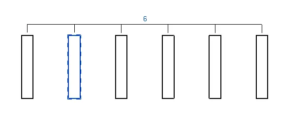
- This is how we can create the array of the model elements.
Question2) Using Revit and the project used from week 6 to 8 prepare a schedule for the following
a. Walls
b. Doors
c. Windows
d. Material – Concrete/Wood.
AIM: To prepare a schedule using the Revit Software for the following elements :
a. Walls
b. Doors
c. Windows
d. Material – Concrete/Wood.
INTRODUCTION: Revit software allows the user to create the schedules with ease. It helps us to create the schedules for the different elements in a very easy manner. Basically schedule is a table that contains important information regarding the elements that we are using like the cost of the element,height,width,area,volume and the other parameters related to the elements. So in this section we will be able to understand the concept of how to create/prepare a schedule. So in this question we will be discussing about the scheduling of the elements in a very detailed manner.
PROCEDURE:
- So in order to create a schedule first of all we have to go to the we have to go to the View tab,in that tab there is an option called schedule click on that nd there is another option called Schedule/Quantities click on that option as shown in the below figure:

- After selecting the schedule/quantity a new dialouge box appears on the screen called New Schedule,there are options like Filter list,Category,Name,Phase. In that dialouge box edit the parameters and then press click as shown in the below figure:
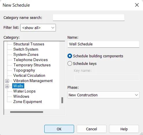
(a) WALL:
- So the parameters that are selected for the wall are showing below in the figure:
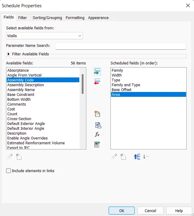
- After selected the scheduled fields click on the OK button and now the schedule for the wall have been created as shown in the below figure:
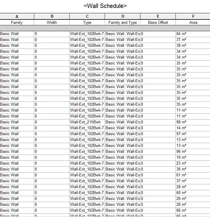
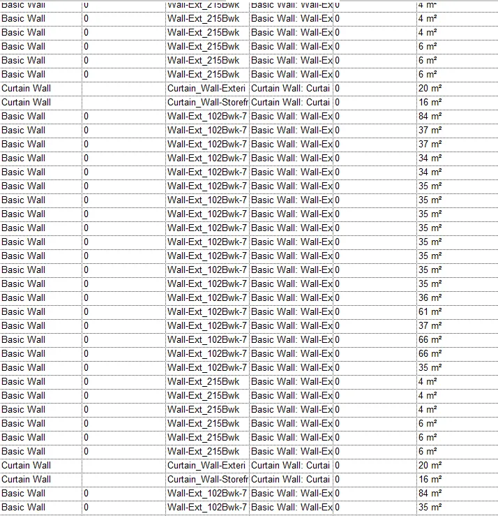
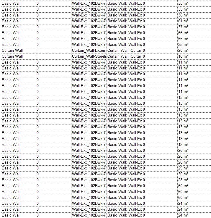
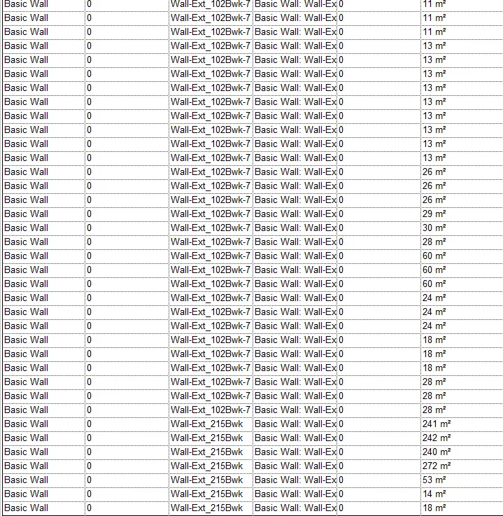
- Similary repeat the steps in order to create the schedule for the different elements.
(b) DOORS:
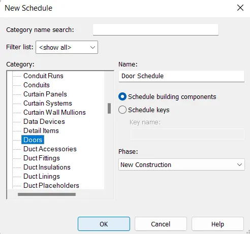
- Select the schedule/quantity a new dialouge box appears on the screen called New Schedule,there are options like Filter list,Category,Name,Phase. In that dialouge box edit the parameters and then press click as shown in the below figure:
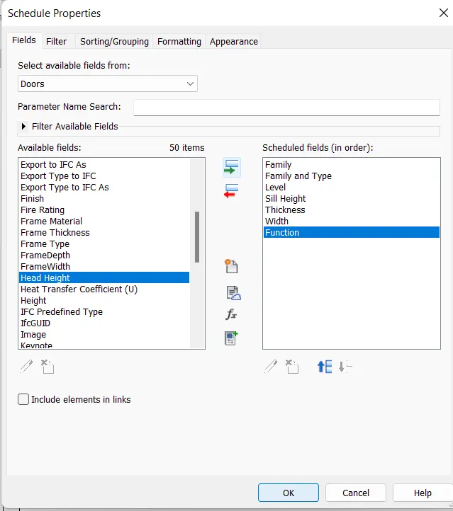
- So the parameters that are selected for the doors are showing below in the figure:
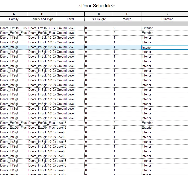
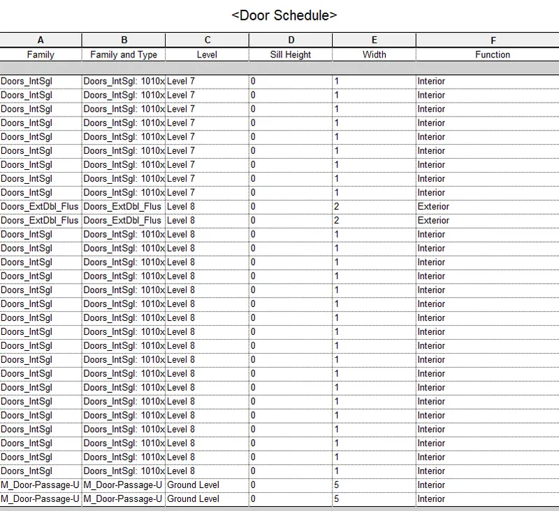
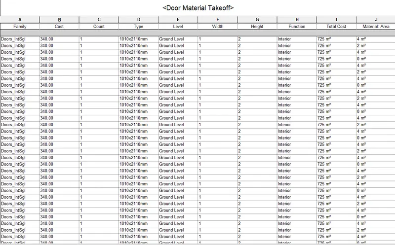
- After selected the scheduled fields click on the OK button and now the schedule for the door have been created as shown in the below figure:
(c) WINDOWS:
- Select the schedule/quantity a new dialouge box appears on the screen called New Schedule,there are options like Filter list,Category,Name,Phase. In that dialouge box edit the parameters and then press click as shown in the below figure:
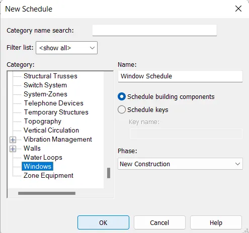
- So the parameters that are selected for the windows are showing below in the figure:
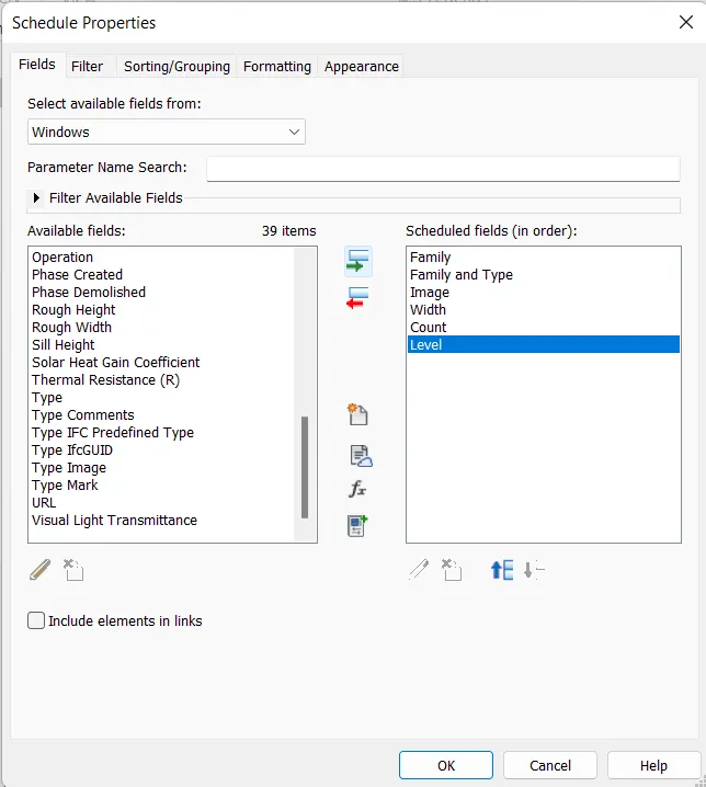
- After selected the scheduled fields click on the OK button and now the schedule for the windows have been created as shown in the below figure:
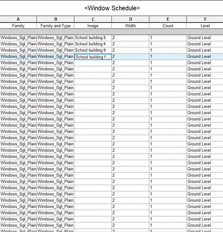
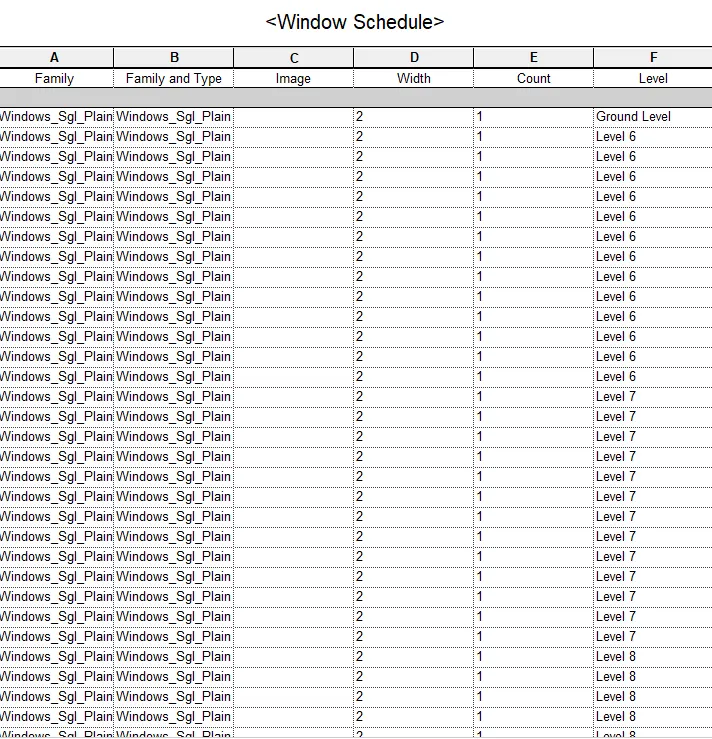
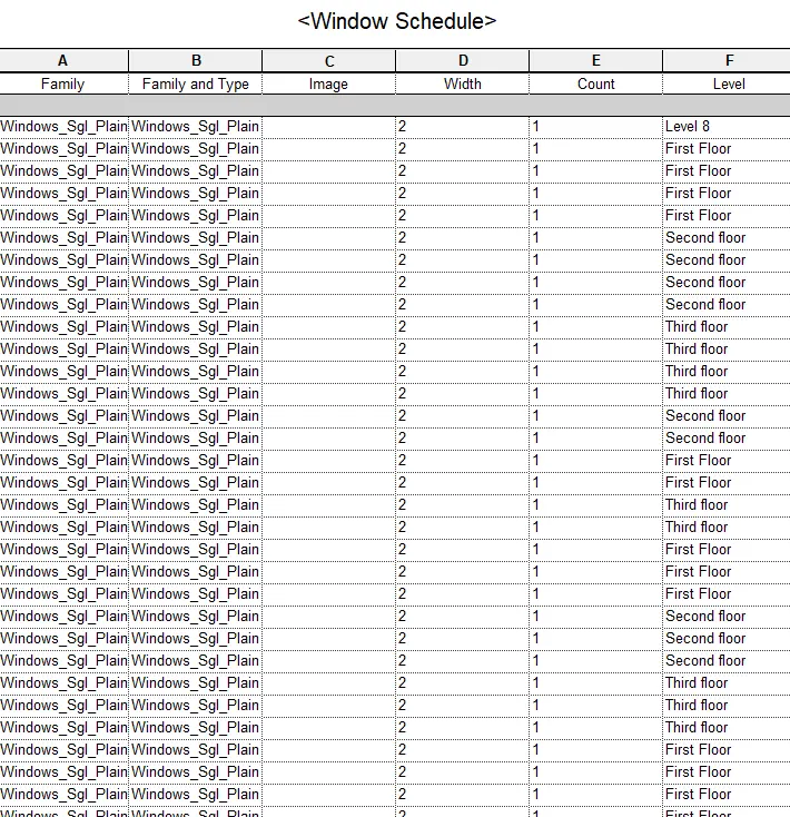
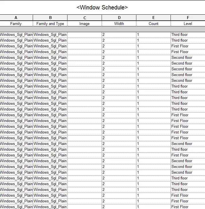
(d) Material – Concrete/Wood:
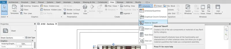
- So in order to create a schedule first of all we have to go to the we have to go to the View tab,in that tab there is an option called schedule click on that nd there is another option called Material Takeoff click on that option as shown in the below figure:
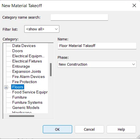
- After selecting the schedule/quantity a new dialouge box appears on the screen called New Schedule,there are options like Filter list,Category,Name,Phase. In that dialouge box edit the parameters and then press click as shown in the below figure:
- So the parameters that are selected for the Material are showing below in the figure:
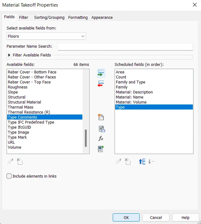
- After selected the scheduled fields click on the OK button and now the schedule for the Materal have been created as shown in the below figure:
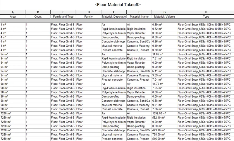
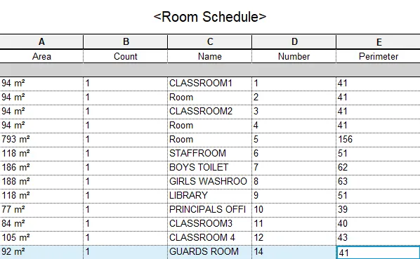
Question3) Using Revit Calculate area and volume of each room in the model with appropriate room tags applied to each room. Prepare a schedule report for area and volume of each room.
AIM: Using Revit Calculate area and volume of each room in the model with appropriate room tags applied to each room. Prepare a schedule report for area and volume of each room.
INTRODUCTION: Revit software allows the user to create the schedules with ease. It helps us to create the schedules for the different elements in a very easy manner. Basically schedule is a table that contains important information regarding the elements that we are using like the cost of the element,height,width,area,volume and the other parameters related to the elements. So in this section we will be able to understand the concept of how to create/prepare a schedule. So in this question we will be discussing about the scheduling of the elements in a very detailed manner.
PROCEDURE:
- So in order to create a schedule first of all we have to go to the we have to go to the View tab,in that tab there is an option called schedule click on that nd there is another option called Schedule/Quantities click on that option as shown in the below figure:
- After selecting the schedule/quantity a new dialouge box appears on the screen called New Schedule,there are options like Filter list,Category,Name,Phase. In that dialouge box edit the parameters and then press click as shown in the below figure:
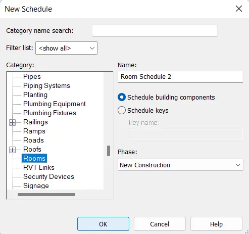
- So the parameters that are selected for the wall are showing below in the figure:
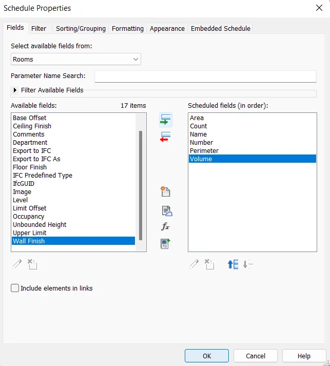
- After selected the scheduled fields click on the OK button and now the schedule for the wall have been created as shown in the below figure:
Question4) Using the same schedule using the unit cost rate for materials available in the internet, prepare total cost of materials used in the project
a. Total Cost of Materials
b. Individual Material Take off
AIM: Using the same schedule using the unit cost rate for materials available in the internet, prepare total cost of materials used in the project
a. Total Cost of Materials
b. Individual Material Take off
INTRODUCTION: Revit software allows the user to create the schedules with ease. It helps us to create the schedules for the different elements in a very easy manner. Basically schedule is a table that contains important information regarding the elements that we are using like the cost of the element,height,width,area,volume and the other parameters related to the elements. So in this section we will be able to understand the concept of how to create/prepare a schedule. So in this question we will be discussing about the scheduling of the elements in a very detailed manner.
PROCEDURE:
a. Total Cost of Materials
b. Individual Material Take off
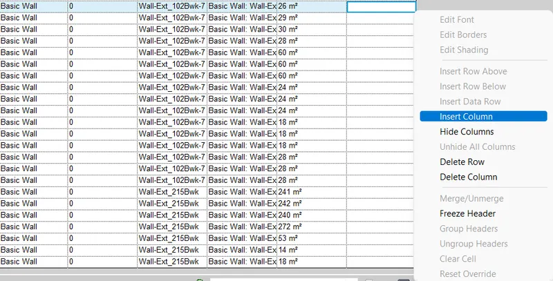
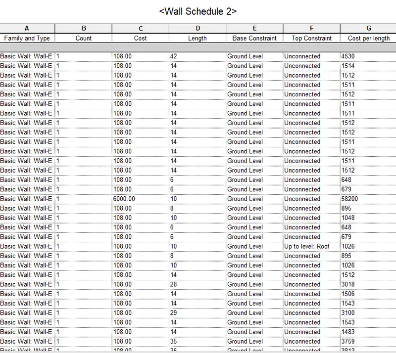
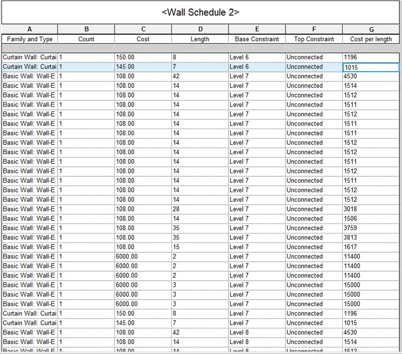
- So in order to create a schedule of total cost of the material in the existing schedule that we just prepared earlier,we need to insert a column named total cost in that prepared schedule.
- So to insert a new column in the existing schedule we just need to righ-click the button and then there is an option called Insert column as shown in the below figure:
- So in order to create a schedule first of all we have to go to the we have to go to the View tab,in that tab there is an option called schedule click on that nd there is another option called Schedule/Quantities click on that option as shown in the below figure:
- After selecting the schedule/quantity a new dialouge box appears on the screen called New Schedule,there are options like Filter list,Category,Name,Phase. In that dialouge box edit the parameters and then press click as shown in the below figure:
- In this box there is an option called fx to calculate the formulas,just click on that the new window appears on the screen called calculated value In this fill options accordingly.
- Apply the formula for the total cost. And then press OK.
- So the parameters that are selected for the wall are showing below in the figure:
- After selected the scheduled fields click on the OK button and now the schedule for the wall have been created as shown in the below figure:
(a) WALL:
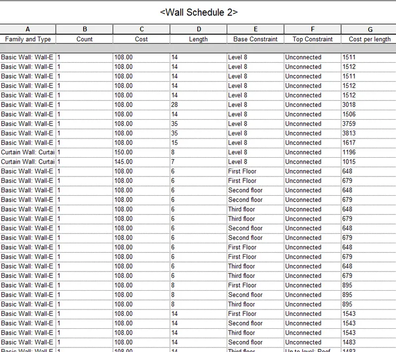
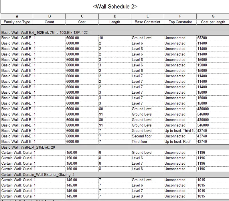
- Do the same procedure for all the elements;
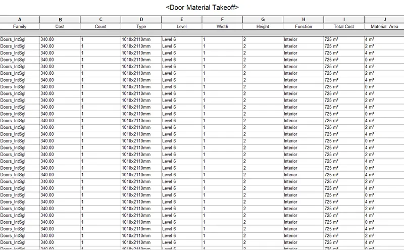
(b) DOORS:
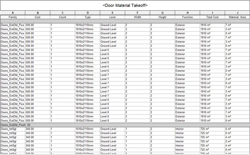
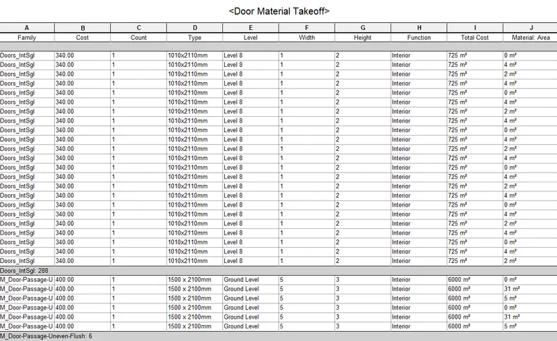
(c) WINDOW:
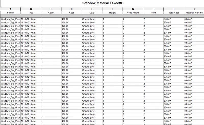
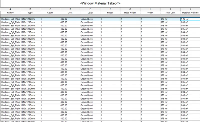
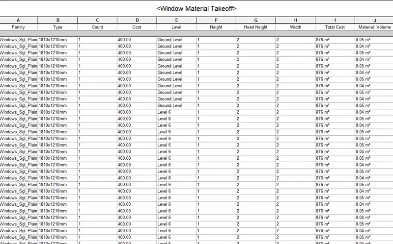
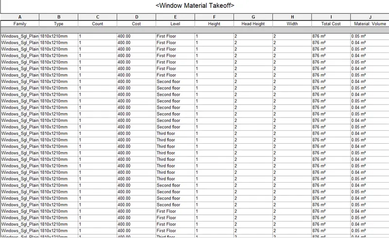
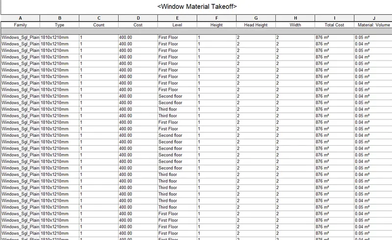
Question5) Using the concept of Visual Programming discussed in class, list a flowchart for the following scenario
a. How to decide framings for a structure using Dynamo ?
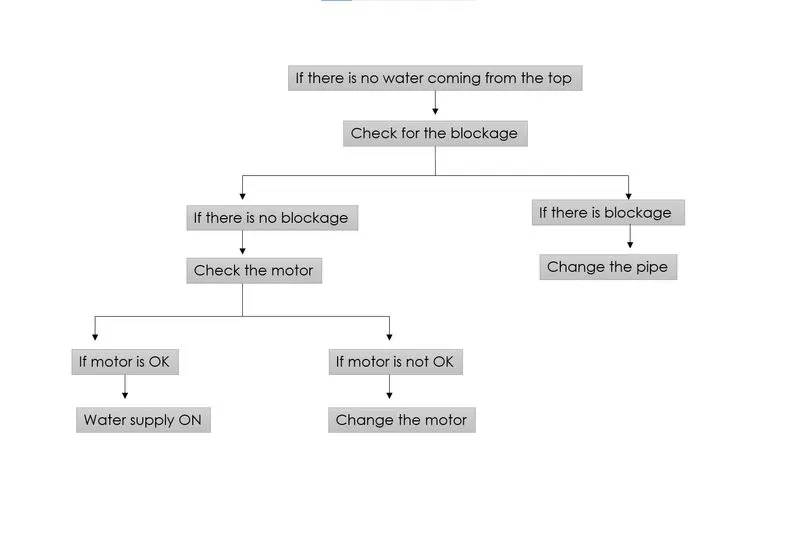
b. If there is no water coming from the pipes
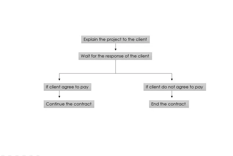
c. If request for money from client has been declined for the project.
Answer.
a. How to decide framings for a structure using Dynamo ?
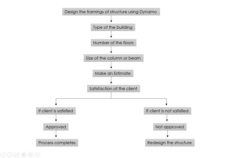
b. If there is no water coming from the pipes
c. If request for money from client has been declined for the project.
Question 6) List the parameters associated with each model element
a. Wall
b. Floor
c. Door
d. Window
e. Table
f. Building
AIM: To list the parameters that are associated with each model elements like wall,floor,door,window,table and building.
INTRODUCTION: In this section we will be able to learn about the different parameters that are associated to the different elements. Revit allows the user to edit these different parameters using the edit option. In this section we will be able to understand the different parameters of different elements in a very detailed manner.The whole procedure has been discussed below in the procedure section.
PROCEDURE:
- In order to list the different parameters that are associated to the each model,first we have to open the Revit Software 2023.
- Here are the lists of the parameters that are associated with the models:
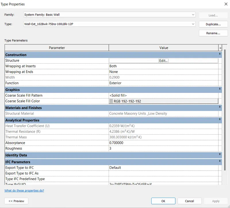
(a) WALL:
- So the parameters that are associated with the walls are listed below:
- Type of the wall.
- Thickness of the wall.
- Cost of the wall.
- Width of the wall.
- Length of the wall.
- Materials and finishes.
- Height of the wall.
- Construction.
- Graphics.
- Analytical properties.
- Identity data.
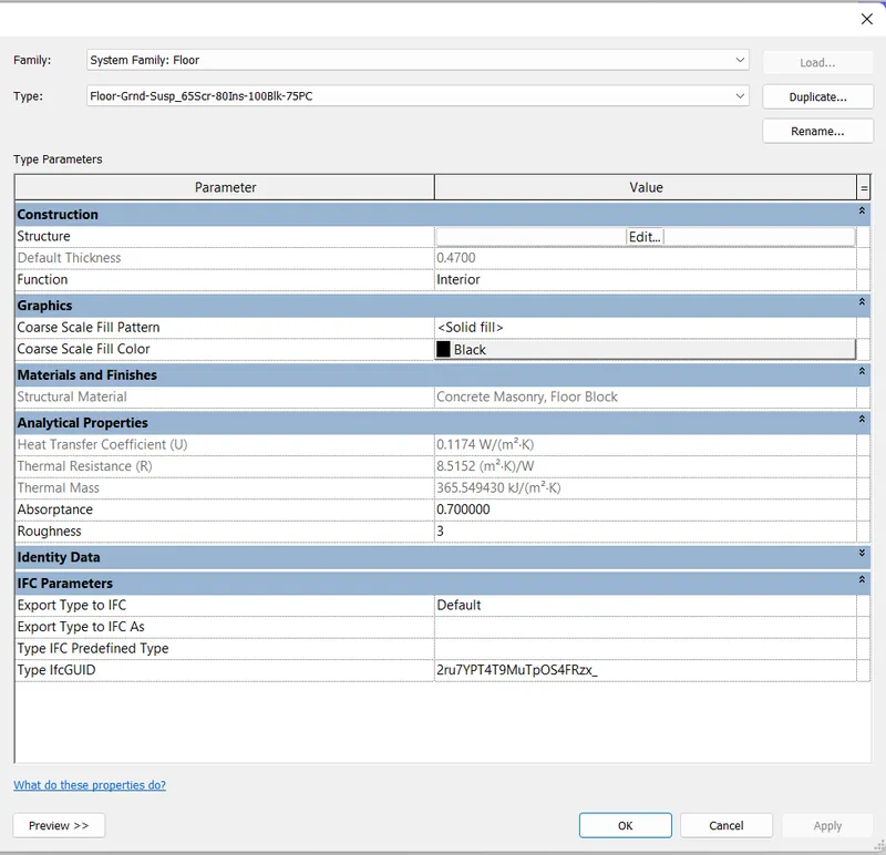
(b) FLOOR:
- Type of the floor.
- Material and finishes.
- Cost of the floor.
- Width of the floor.
- Thickness of the floor.
- Volume of the floor.
- Length of the floor.
- Area of the floor.
- Construction.
- Graphics.
- Analytical properties.
- Identity data.
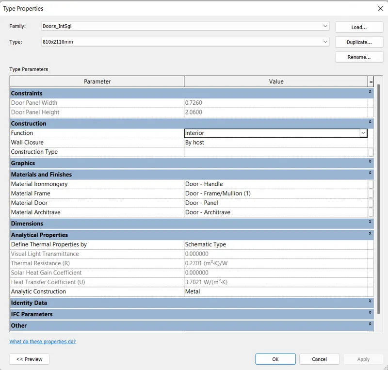
(c) DOOR:
- Height of the door.
- Width of the door.
- Breadth of the door.
- Thickness of the door.
- Material and finishes.
- Type of the door.
- Constraints.
- Construction.
- Graphics.
- Dimensions.
- Analytical Properties.
- Identity Data.
- IFC Parameter.
- Others.
(d) WINDOWS:
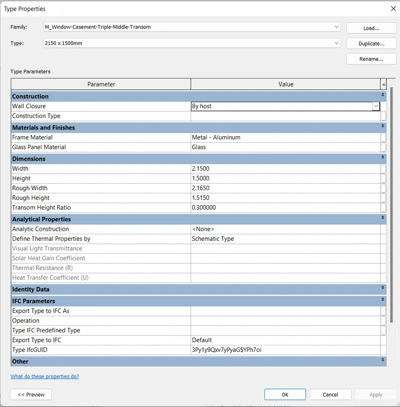
- Thickness of the window.
- Materials and finishes.
- Type of the windows.
- Construction.
- Dimensions of the windows.
- Analytical properties.
- Identity data.
- IFC parameters.
- Others.
(e) TABLE:
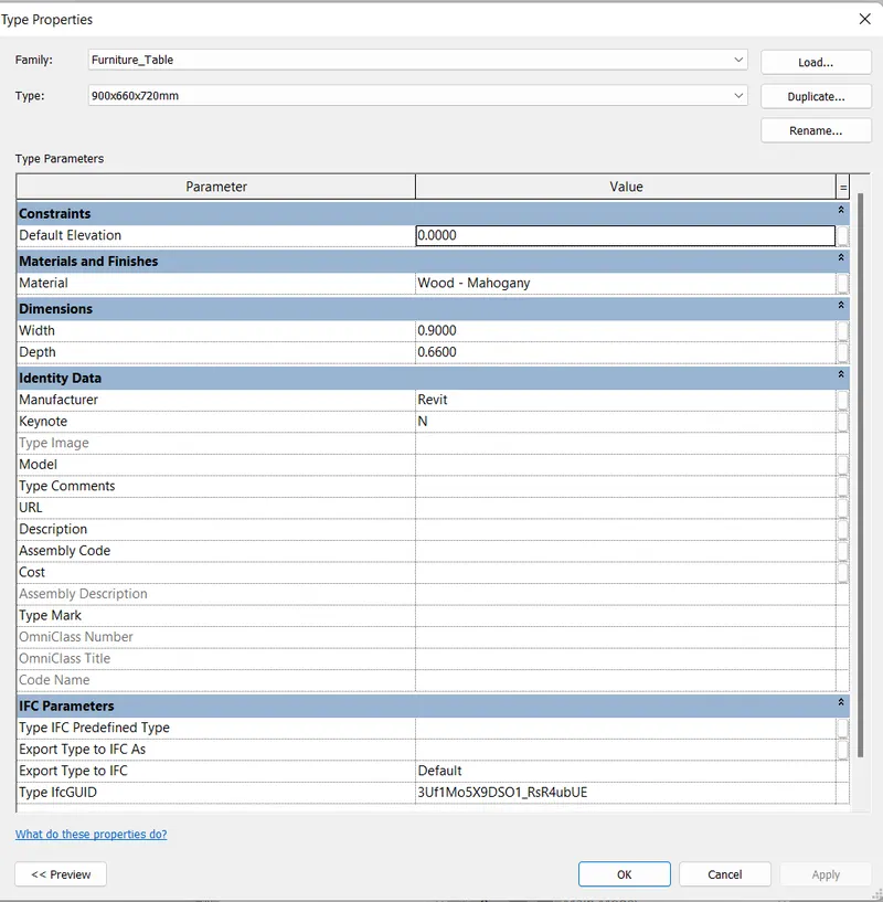
- Constraints.
- Material and finishes.
- Dimensions.
- Identity data.
- IFC Parameter.
(f) Building:
- Height of the building.
- Type of the building.
- Number of the floors.
- Area of the building.
- Length of the building.