Planetary Gear analysis using solidworks MBD
AIM : Planetary gear analysis using solidworks MBD.
OBJECTIVE :
- Calculate the pitch circle diameter and the number of teeth for the planet gear.
- Angular Velocity of that input and output part is plotted as graph.
- conclude the result.
Introuction :
An epicyclic gear train (also known as planetary gear) consists of two gears mounted so that the center of one gear revolves around the center of the other. A carrier connects the centers of the two gears and rotates to carry one gear, called the planet gear or planet pinion, around the other, called the sun gear or sun wheel. The planet and sun gears mesh so that their pitch circle roll without slip. A point on the pitch circle of the planet gear traces an epicycloidal curve. In this simplified case, the sun gear is fixed and the planetary gear(s) roll around the sun gear.
An epicyclic gear train can be assembled so the planet gear rolls on the inside of the pitch circle of a fixed, outer gear ring, or ring gear, sometimes called an annular gear. In this case, the curve traced by a point on the pitch circle of the planet is a hypocycloid.
The combination of epicycle gear trains with a planet engaging both a sun gear and a ring gear is called a planetary gear train. In this case, the ring gear is usually fixed and the sun gear is driven.
Epicyclic gears get their name from their earliest application, which was the modelling of the movements of the planets in the heavens. Believing the planets, as everything in the heavens, to be perfect, they could only travel in perfect circles, but their motions as viewed from Earth could not be reconciled with circular motion.
Gear ratio of standard epicyclic gearing:
The gear ratio of an epicyclic gearing system is somewhat non-intuitive, particularly because there are several ways in which an input rotation can be converted into an output rotation. The three basic components of the epicyclic gear are:
- Sun: The central gear
- Carrier: Holds one or more peripheral Planet gears, all of the same size, meshed with the sun gear
- Ring or Annulus: An outer ring with inward-facing teeth that mesh with the planet gear or gears
The overall gear ratio of a simple planetary gearset can be calculated using the following two equations, representing the sun-planet and planet-ring interactions respectively:

where
 is the angular velocity of the Ring, Sun gear, Planet gears and planet Carrier respectively, and
 is the Number of teeth of the Ring, the Sun gear and each Planet gear respectively.
from which we can deduce that:

or
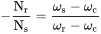
Considering  .
Alternatively, if the number of teeth on each gear meets the relationship  , this equation can be re-written as the following:

where

These relationships can be used to analyze any epicyclic system, including those, such as hybrid vehicle transmissions, where two of the components are used as inputs with the third providing output relative to the two inputs.
In many epicyclic gearing systems, one of these three basic components is held stationary; one of the two remaining components is an input, providing power to the system, while the last component is an output, receiving power from the system. The ratio of input rotation to output rotation is dependent upon the number of teeth in each gear, and upon which component is held stationary.
In one arrangement, the planetary carrier (green) is held stationary, and the sun gear (yellow) is used as input. In this case, the planetary gears simply rotate about their own axes (i.e., spin) at a rate determined by the number of teeth in each gear. If the sun gear has Ns teeth, and each planet gear has Np teeth, then the ratio is equal to −Ns/Np. For instance, if the sun gear has 24 teeth, and each planet has 16 teeth, then the ratio is −24/16, or −3/2; this means that one clockwise turn of the sun gear produces 1.5 counterclockwise turns of each of the planet gear(s) about its axis.
This rotation of the planet gears can in turn drive the ring gear (not depicted in diagram), in a corresponding ratio. If the ring gear has Nr teeth, then the ring will rotate by Np/Nr turns for each turn of the planet gears. For instance, if the ring gear has 64 teeth, and the planets 16, one clockwise turn of a planet gear results in 16/64, or 1/4 clockwise turns of the ring gear. Extending this case from the one above:
- One turn of the sun gear results in
 turns of the planets
- One turn of a planet gear results in
 turns of the ring gear
So, with the planetary carrier locked, one turn of the sun gear results in  turns of the ring gear.
The ring gear may also be held fixed, with input provided to the planetary gear carrier; output rotation is then produced from the sun gear. This configuration will produce an increase in gear ratio, equal to 1+Nr/Ns.
If the ring gear is held stationary and the sun gear is used as the input, the planet carrier will be the output. The gear ratio in this case will be 1/(1 + Nr/Ns) which can also be written as 1:(1 + Nr/Ns). This is the lowest gear ratio attainable with an epicyclic gear train. This type of gearing is sometimes used in tractors and construction equipment to provide high torque to the drive wheels.
In bicycle hub gear, the sun is usually stationary, being keyed to the axle or even machined directly onto it. The planetary gear carrier is used as input. In this case the gear ratio is simply given by (Ns+Nr)/Nr. The number of teeth in the planet gear is irrelevant
In this example, the carrier (green) is held stationary while the sun gear (yellow) is used as input. Analysis assumes a common gear design modulus. The planet gears (blue) turn in a ratio determined by the number of teeth in each gear. Here, the ratio is −24/16, or −3/2; each planet gear turns at 3/2 the rate of the sun gear, in the opposite direction.
WHAT IS GEAR :
A Gear May be defined as any tooth member designed to transmit (or) Receive motion from another member by successively engaging the tooth. the function of gear is to work smoothly while transmitting motion or torque. for this, the angular velocity ratio at all times should remain constant.
GEAR TERMINOLOGY :
Generally, gear is identified by the pitch circle diameter, Module and Number of teeth. if we have any two-parameter between the module, pitch of circle and number of teeth we can find the third one.
Input :
- Ring Gear
- Module = 2.5 (You must use the metric system in design modeler)
- Number of teeth = 46
- Sun Gear
- Number of teeth = 14
- Input Speed of the Gear = 200 rpm.
- Number of planet gears = 4
The dimensions of the carrier depend on the shaft diameter of the planet gear.
With the above input parameters, to run a simulation on the following cases,
| Sl.No | Input | Output | Fixed |
| 1 | Sun Gear | Carrier | Ring Gear |
| 2 | Ring Gear | Carrier | Sun Gear |
| 3 | Sun Gear | Ring Gear | Carrier |
CALCLULATION :
Before proceeding further we need to calculate the unknown parameters of the gear which is as follows :
`m = d/T`
Where:-
m = module
(The module is also known as Addendum which is the ratio of reference diameter (or) Pitch diameter to the number of teeth. a module is the unit of size that indicates how big or small a gear is.)
d = pitch diameter
(Pitch diameter is a diameter of the pitch circle.)
T = number of teeth
1. for Ring gear:
Given :
m = 2.5
T = 46
d = ?
therefore, `d = m xxT` ;
`d = 2.5 xx46`
`d = 115`
2. for sun gear :
Given : `T = 14`
as we know module is same for gears
hence , `d = m xx T`
`d = 2.5 xx 14`
`d = 35`
3. for planetary gears :
In planet gear, we need to find out pitch diameter and number of teeth also. so here we cannot directly apply the formula as above. here we need to first find out the value of pitch diameter. as we know,
[ Radius of Ring Gear = Radius of Sun gear + Diameter of planet gear ]
[ 115/2 = 35/2 + Diameter of planet gear ]
after solved this we get
therefore, Diameter of planet gear
`d = 40`
now using same formula we get number of teeth
`T = d/m`
`T = 40/2.5`
`T = 16`
Design Parts :
1. Ring Gear
(ANSI metric)
module = 2.5 ;number of teeth = 46 ; Pressure angle = 20 degree; face width = 20 ; outside diameter = 115.
2. Sun Gear :
module = 2.5 ; number of teeth = 14 ; Pressure angle = 20 degree; face width = 20 ; Nominal shaft diameter = 11
3. Planetary gear :
module = 2.5 ;number of teeth = 16 ; Pressure angle = 20 degree; face width = 20 ; Nominal shaft diameter = 11.
4. design of carrier :
parameters taken from gears size.
Assembling of parts :
Results :
1. Case_study_1
following graph is obtained :
2. Case_study_2 :
Following graph is obtained
3. Case_study_3
Following Graph is obtained
ANIMATION :
1. CASE_STUDY_1
2. case_study_2 :
Input : speed = 200 , FPS = 60 , playspeed = 0.1x
3. case_study_3 :
Input : speed = 200 , FPS = 60 , playspeed = 0.1x
Conclusion :
Planetary gear sets consists of sun gear, 4 Planet gears and ring gear. all the parts are assembled to make a planetary gear train.This assmebly is made such that all the componets can move independently and if we fix any one component i.e. sun or planet or ring gear. the other two components will rotate freely. Planetary gear sets are mainly used in automatic transmissions of automobiles.
In Case_Study_1 : Here we can see that the initial angular velocity is zero and when the rotor starts rotating the angular velocity increases drastically. we also see that there is fluctuation in the angular velocity which is caused due to the multiple components in the assembly. As our assembly gets momentum the fluctuation in the angular velocity reduces and it maintains a constant speed
In Case_study_2 : As plot defines the angular velocity is zero at the initial stage and rotor start rotating the angular velocity increases drastically. but fluctuation induced is decreased with time and maintain a constant rate.
In Case_study_3 : the carrier is fixed, so the planet gears will only spin and will not revolve around the sun gear, and the output will be obtained at the ring gear which will spin in an opposite direction to the sun gear and hence a reverse gear will be obtained.
- The angular velocity obtained is maximum in Case 2
- Small disturbances are produced in the output due to mating of gears
- The output angular velocity is lower than the input angular velocity in each case.
Reference :