Planetary Gear
Aim :- To carry out the simulation and motion analysis of planetary gear to evaluate the output angular velocity
Objective :-
- To find out the pitch circle diameter and teeth of the planet gear
- To find pitch circle diameter of sun gear and ring gear
- To plot the graphs of angular velocity at outlet for given cases
Theory :- An epicyclic gear train(also known as a planetary gearset) consists of two gears mounted so that the center of one gear revolves around the center of the other. A carrier connects the centers of the two gears and rotates to carry one gear, called the planet gear or planet pinion, around the other, called the sun gear or sun wheel.
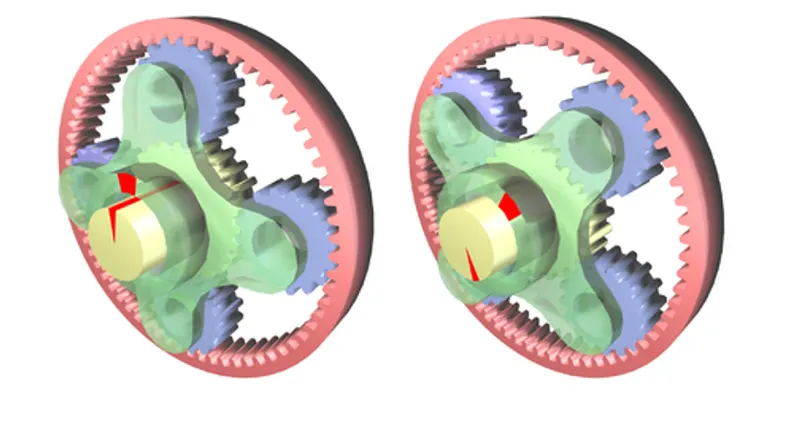
Applications:- Planetary gearing, with its inherent in-line shafting and cylindrical casing, is often recognized as the compact alternative to standard pinion-and-gear reducers. Being suited for a wide range of applications – from electric screwdrivers to bulldozer power trains – these units are strong contenders when space and weight versus reduction and torque are chief concerns.
Given data to carry out simulation
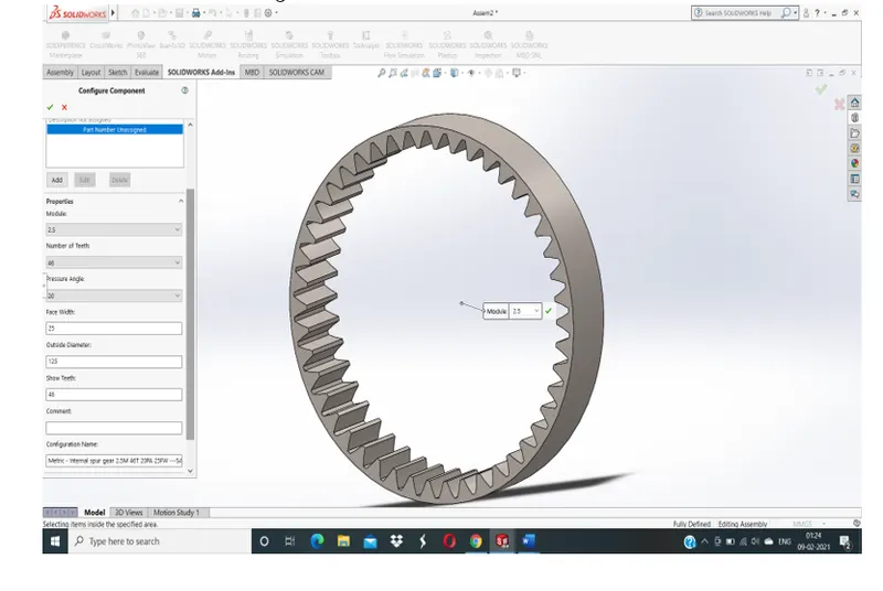
- Ring gear
Module = 2.5
No. of teeth = 46
Outside diameter = 125
Facewidth = 25
Pitch circle diameter = module * teeth
=2.5 * 46
PCD = 115 mm
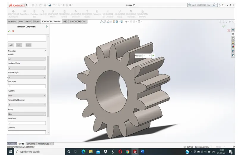
- Sun gear
Module = 2.5
No. of teeth = 14
PCD = M * T
= 2.5 * 14
PCD = 35 MM
Nominal shaft diameter = 18 mm
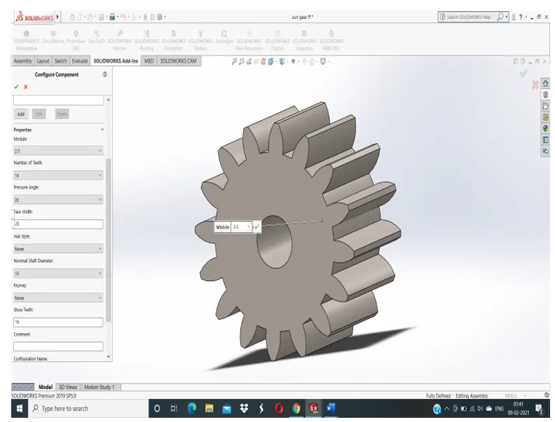
- Planet gear
PCD of planet gear = (PCD of ring gear – PCD of sun gear)/2
= (115 – 35)/2
PCD of planet gear = 40 mm
No. of teeth = PCD / MODULE
= 40 / 2.5
No. of teeth = 16
Nominal shaft diameter = 10 mm
Drawings for measurements
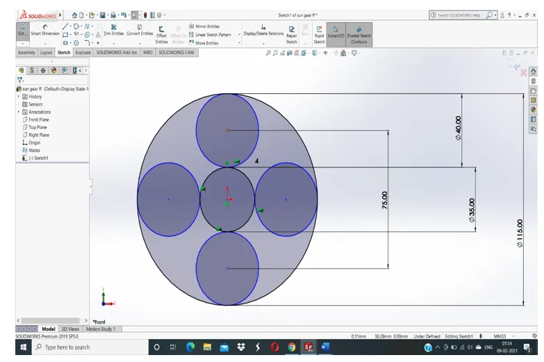
Drawings for shaft diameters of planet and sun gear
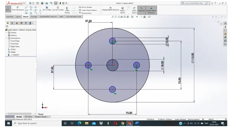
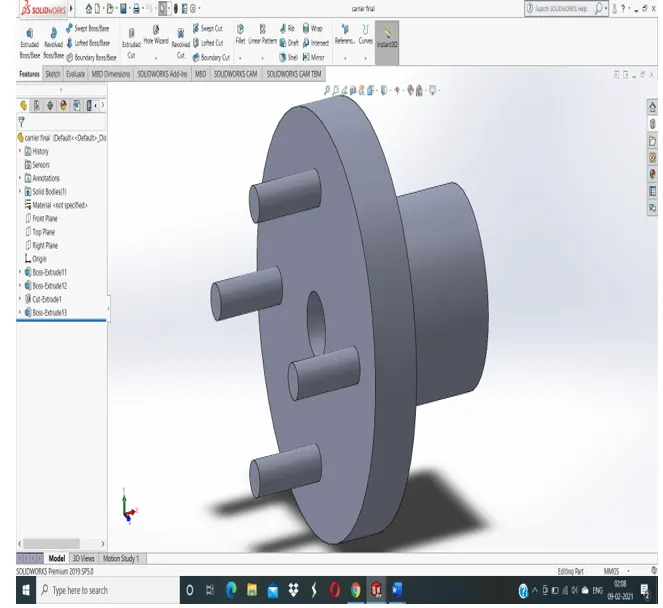
Carrier shaft
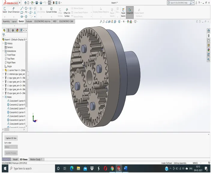
GEAR ASSEMBLY
Procedure
- First we calculate all the required parameters required for the drawing.
- Then, we have to draw a sketch of planetary gears using the given paramers.
- From that drawing we find the center to center distance between the shafts from the origin.
- Then we draw the 2D sketch of carrier on which planetary shafts are mounted.
- Then we have to extrude the 2D sketch into 3D model by using the extrude option.
- Then importing the carrier in the assembly to assemble the gear set.
- Then we import the spur gear as sun from the design library with required parameters and 4 spur gears as planets with required parameters.
- Then we select the internal spur gear with required parameters.
- Then we assemble all the gears with respect to their shafts
We have to consider the following given cases
|
Sr.No |
Input |
Output |
Fixed |
|
1 |
Sun Gear |
Carrier |
Ring Gear |
|
2 |
Ring Gear |
Carrier |
Sun Gear |
|
3 |
Sun Gear |
Ring Gear |
Carrier |
PLOTS
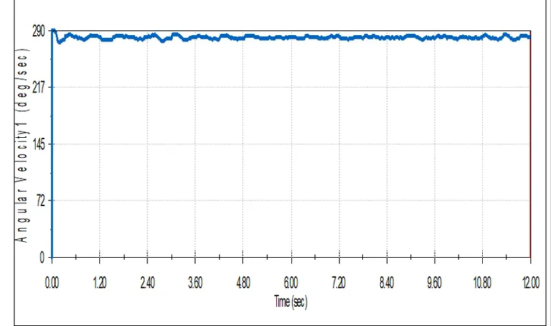
CASE 1
Input :- sun gear(200 rpm)
Output :- carrier
Fixed :- Ring gear
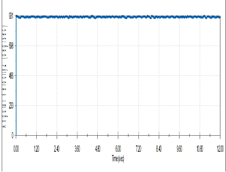
Case 2
Input :-Ring gear(200 rpm)
Output:-Carrier
Fixed:-Sun gear
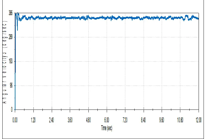
Case 3
nput:-Sun gear(200 rpm)
Output:-Ring gear
Fixed:-Carrier
Conclusion:-
Case 1
- -In this case , the output angular velocity is low as compared to angular velocities in case 2 and case 3.
- Angular velocity fluctuates averagely with respect to time.
Case 2
- In this case the angular velocity is high among all three cases.
- Angular velocity is more uniform with respect to time
Case 3
- In this case the output velocity is average .
- Angular velocity fluctuates more with respect to time
Individual parts view link