MBD Simulation on a Piston Assembly
AIM :- To carry out MBD simulation on piston assembly to obtain the linear displacement of piston head.
INTRODUCTION :- The piston assembly consists of the following main parts:-
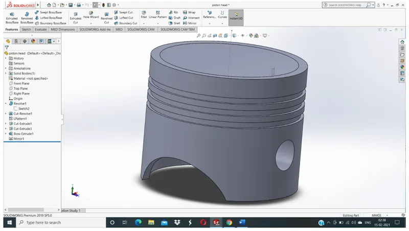
- Piston head
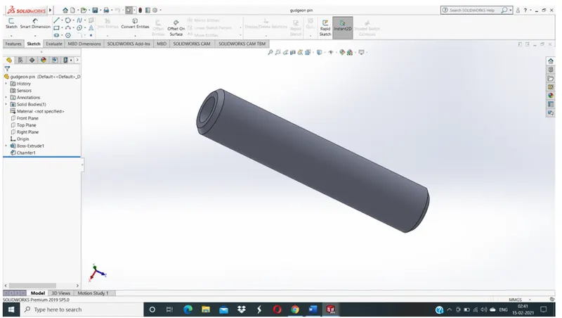
- Gudgeon pin
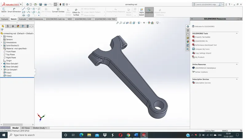
- Connecting rod
- Crank
The piston head reciprocates about its axis. The reciprocating motion of piston head is converted into rotary motion of crank with the help of connecting rod.
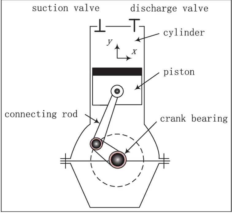
FUNCTIONS OF PISTON ASSEMBLY :-
- It transmits gas force generated during combustion to the connecting rod and crankshaft.
- As piston is connected to small end of the connecting rod with the help of gudgeon pin. It guides the connecting rod when gas force is transmitted.
- Air/fuel mixture is compressed by piston.
- Piston rings restrict the flow of hot gases into the crankcase. This is also referred as blow by control.
- Piston rings lubricate the cylinder wall.
- Piston rings restrict the amount of oil from crankcase into the gap between piston and cylinder head.
- Heat is transferred to the cylinder wall from piston by piston rings.
THEORY
The crank of the piston is given a constant angular velocity of 2000 rpm. The rotary motion of connecting rod is converted into reciprocating motion of piston. We first carry out the simulation of the piston assembly. Then it would be easy to obtain the linear displacement of the piston head. By applying the given parameters to the motion study, the simulation is carried out.
The parameters for motion study are:-
- Crank speed = 2000 rpm
- Frames = 12000
- Use precise contact
- Material = steel dry
By using the dimensions given in the 2D drawing we create the 3D parts of piston assembly. For creating the components we use the solid works software. Open the software. Select the part option. Select the plane and start the drawing.
Components of piston assembly :-
PISTON HEAD
GUDGEON PIN
CONNECTING ROD
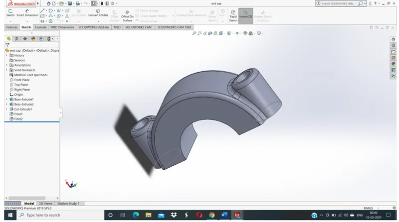
END CAP
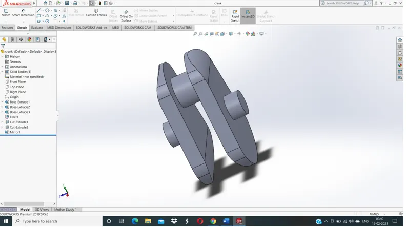
CRANK
INDIVIDUAL COMPONENTS LINK
https://1drv.ms/u/s!AjlHd5izphcngRbp_2eaJYe9tBsj?e=jmCWAm
PISTON ASSEMBLY
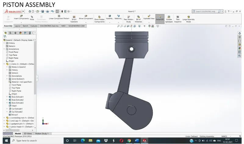
The motion analysis is going to be carried out in three different conditions :-
|
Sr no. |
Wrist pin offset |
Crank speed (rpm) |
|
1 |
0 mm |
2000 |
|
2 |
10mm positive |
2000 |
|
3 |
10mm negative |
2000 |
RESULTS
First case 0 mm offset
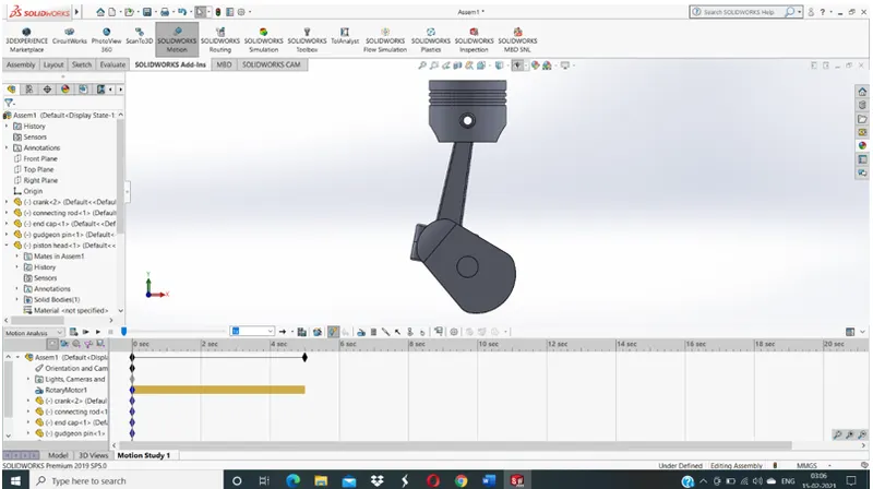
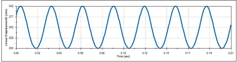
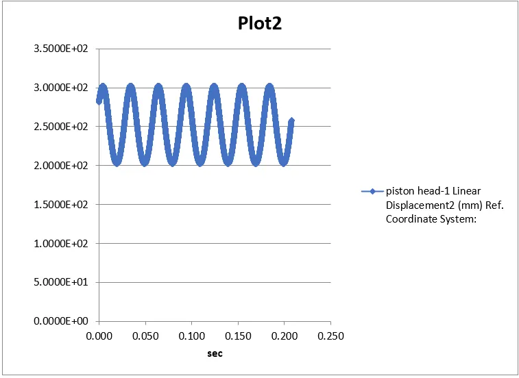
- From the plots we observe that the maximum linear velocity of the piston head is 302.49.
- The linear velocity of piston head fluctuates between the values 203 to 302
10 mm positive offset
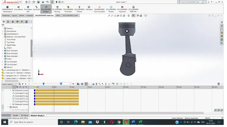
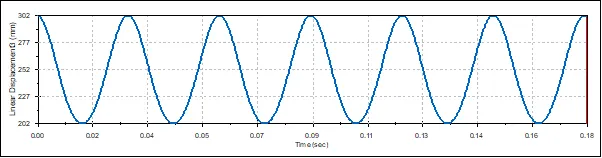
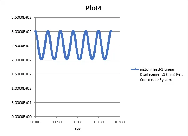
The linear displacement remains almost the same during the positive offset as that of 0 mm offset
10 mm negative offset
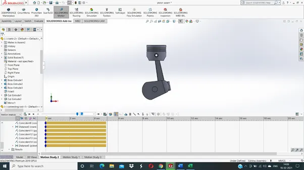
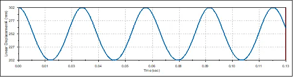

- Same as the other case,the displacement of the piston head does not vary to a great extent.
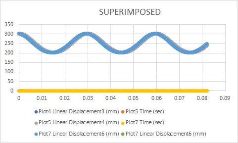
- From the plots it is observed that the linear displacement of piston head is approximately same in the above three cases.
CONCLUSION
- The stress induced in the connecting rod are less during the wrist pin offset as compared to 0 mm offset.