Motion analysis of Planetary gear by using SOLIDWORKS
AIM:
To create a planetary gear system with set of ring gear, sun gear and planet gear and run the simulation for different conditions.
FLOW OF CONTENT/METHODOLOGY :
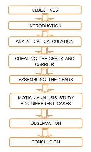
OBJECTIVE :
1) Create a gear through the design library by taking ANSI metric standard.
2) Learn about the gear nomenclature and terminology.
3) Calculating the number of teeth and pitch circle for sun gear, ring gear and planet gear.
4) Simulating the planetary gear for which different cases.
INTRODUCTION :
Planetary gear system :
A planetary gear is also called as epicyclic gear, its consists of one sun gear, one ring gear and four planet gear. The sun gear and ring gear is always rotates about it's own axis, the planet gear is also rotates about it's own axis at carrier is fixed condition. When we fix the sun gear or ring gear, that planet gear revolves around the sun gear with rotates about it's own axis. The planet gear is revolves around the outer side on the sun gear and also revolves around the inner side on a ring gear.
The sun gear and planet gear are external spur gear, the ring gear is internal spur gear. The planetary gear system have set of three different transmission speed, one speed is rotates on reverse direction and another two speed are rotates on forward direction.
Application of planetary gear system :
1) There are used in back gear of lathe, hoists, pulley blocks, wrist watches etc..
2) There are popular for automatic transmission in automobiles.
3) There are used in bicycle for controlling power of pedaling automatically or manually.
4) They are also used for power train between internal combustion engine and an electric motor.
Gear nomenclature and terminologies :
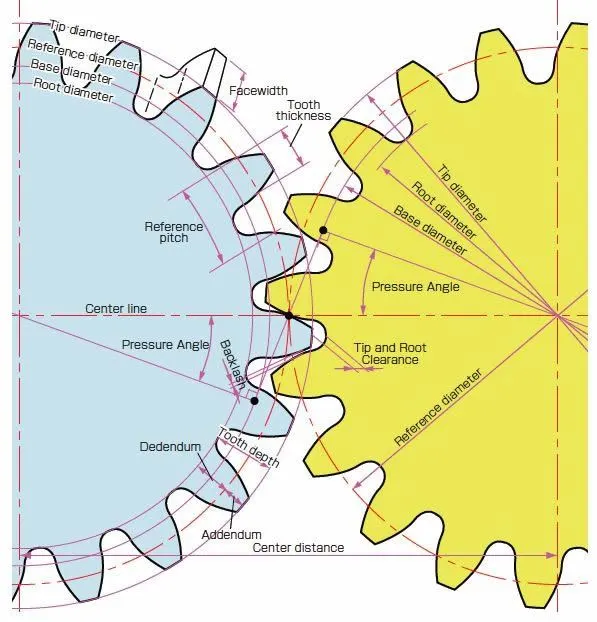
Addendum circle :
The addendum circle coincides with the top of the teeth of a gear and is concentric with the standard pitch circle in radially distant from it by the amount of it's addendum. For external gears, the addendum circle lies on the outside cylinder, while on internal gears the addendum circle lies on the internal cylinder.
Dedendum circle :
The dedendum circle coincides with the standard pitch circle with the standard base circle in radially distant from it by the amount of it's dedendum. For external gears, the dedendum circle lies between base circle and pitch circle, while on internal gears the dedendum circle lies between outside cylinder.
Center distance :
Center distance is the shortest distance between non-intersecting axes. It is measuring along the mutual perpendicular to the axes is called line of center. It applies to spur gear, parallel axis or crossed axis helical gears and worm gearing.
Pressure angle :
Pressure angle in relation to gear teeth also known as the angle of obliquity, the angle between the tooth face and the gear wheel tangent. It is more precisely the angle at a pitch point between the line of pressure ( which is normal to the tooth surface ) and the plane tangent to the pitch surface.
Diametrical pitch :
The diametric pitch is ratio of number of teeth per inch of diameter of the pitch circle.
Module of the gear :
The module of the gear is ratio of metric of diameter of the pitch circle per number of teeth.
ANALYTICAL CALCULATION :
GIVEN DATA :
Ring gear
Module of the gear = 2.5
Number of teeth = 46
Sun gear
Number of teeth = 14
Planet gear
Number of the planet gears = 4
TO FIND :
Pitch circle for ring gear = ?
Pitch circle for sun gear = ?
Pitch circle for planet gear = ?
Number of teeth for planet gear = ?
SOLUTION :
Module of the gear is same for ring gear, sun gear and planet gear
Module of the gear = Pitch circle / Number of teeth
Pitch circle for ring gear :
Module for ring gear = Pitch circle for ring gear / Number of teeth for ring gear
Pitch circle for ring gear = Module for ring gear * Number of teeth for ring gear
= 2.5 * 46
= 115 mm
Pitch circle for sun gear :
Module for sun gear = Pitch circle for sun gear / Number of teeth for sun gear
Pitch circle for sun gear = Module for sun gear * Number of teeth for sun gear
= 2.5 * 14
= 35 mm
Pitch circle for planet gear :
Pitch circle diameter for planet gear = Pitch circle diameter for ring gear - Pitch circle diameter for sun gear
= 115 - 35
= 40 mm
Module for Planet gear = Pitch circle for Planet gear / Number of teeth for Planet gear
Number of teeth for Planet gear = Pitch circle for Planet gear / Module for Planet gear
= 40 / 2.5
= 16
Tabulation describes the gear inputs
| Gears Parameters | Module(m) in mm | Pitch circle in mm | Number of teeth |
| Ring gear | 2.5 | 115 | 46 |
| Sun gear | 2.5 | 35 | 14 |
| Planet gear | 2.5 | 40 | 16 |
CREATING THE GEARS & CARRIER :
All the gears are creating from assembly section. Go to the design library, open the tool box, Select the suitable standard I prefer ANSI metric it stands for " American national standards Institute " and after that I click on the power transmission. We can select the gears which is suitable for work. This procedure is same for all the gears.
Ring gear :
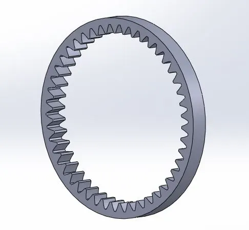
Face width = 12 mm
Diametrical pitch = 2.5
Number of teeth = 32
Pressure angle = 20
Outer diameter = 38 mm
Pitch circle diameter = 115 mm
Sun gear :
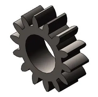
Face width = 12 mm
Diametrical pitch = 2.5
Number of teeth = 14
Pressure angle = 20
Pitch circle diameter = 35 mm
Planet gear :

Face width = 12 mm
Diametrical pitch = 2.5
Number of teeth = 14
Pressure angle = 20
Pitch circle diameter = 35 mm
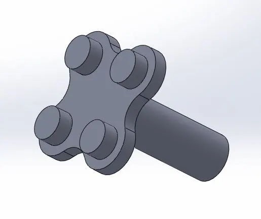
Planetary gear carrier :
A planetary gear carrier is help to hold the planet gear and also allow to rotatary motion.
ASSEMBLING THE GEARS :
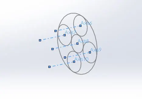
Draw the big circle, it is equal to pitch circle diameter of ring gear and draw a small circle, it is equal to pitch circle diameter of sun gear. Similarly, to draw a four circle for planet gear. Create a referance axis for all circles.
These referance circle and axis has been key play for different cases. Mating the gear axis to corresponding circle axis in proper manner.
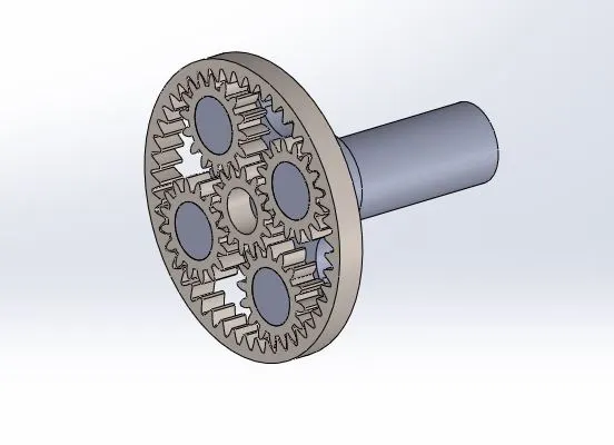
This is assembly view of all gears in single unit. it is called Planetary gear system.
MOTION ANALYSIS STUDY FOR DIFFERENT CASES :
1) Input speed is 200 Revolution per minute is same for all cases.
2) Dry steel material is same for all gears and all cases.
3) Contact selection is same manner for all cases.
4) Frames per second is 25 with precision contact.
Case 1
Ring gear is fixed, Sun gear is input & Carrier gear is Output
Fix the ring gear, provide the input speed to sun gear at 200 RPM on counter clockwise direction. Suppress the concentric circles for four planet gear. Then only the planet gear will revolve around the sun gear and also rotates about on its own axis. The sun gear rotates counter clockwise direction, the planet gear is rotates on clockwise direciton. The carrier is rotates on counter clockwise direction.
Youtube Link for case 1 : https://www.youtube.com/watch?v=lgmnBGJuBVY
Post processing :
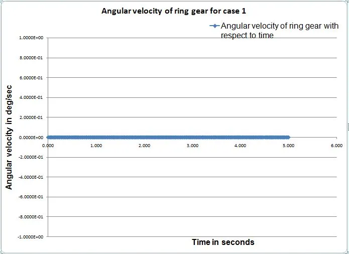
Angular velocity of a ring gear
The ring gear gets to fix in manually, the angular velocity of ring gear is zero over the time.
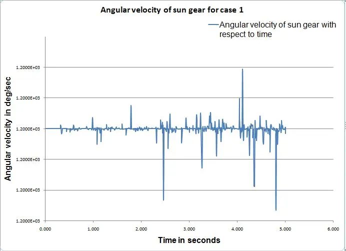
Angular velocity of a Sun gear
We provide the input valve to sun gear at 200 RPM, it is constant over the time period.
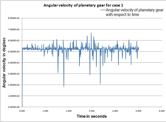
Angular velocity of planet gear
The planet gear is help to power transmitted from sun gear to carrier. The planet gear and sun gear have been engaged to each other, the gear ratio between planet and sun gear is 0.43 approximately. That means 67 % speed has been reduced from sun gear speed in approximately.
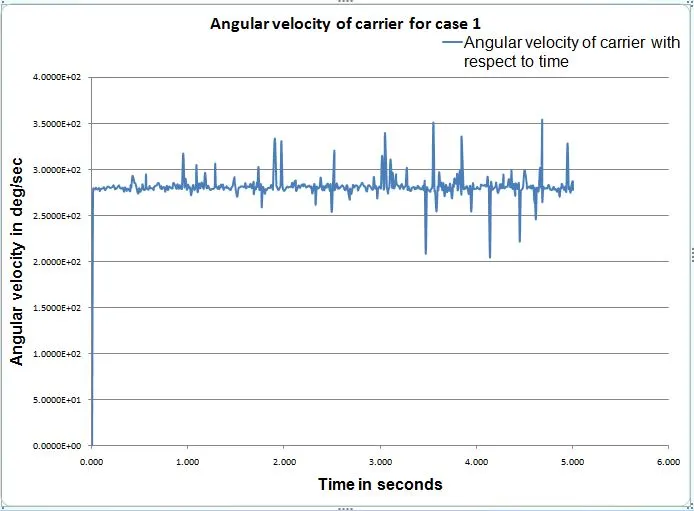
Angular velocity of a Carrier
Final output get from planetary gear carrier, the speed ratio between planet gear and carrier is 0.53 approximately.
Case 2
Sun gear is fixed, Ring gear is input & Carrier gear is Output
Fix the sun gear, provide the input speed to ring gear at 200 RPM on clockwise direction. Unsupress the corresponding concentric circle for four planet gears, it rotates on own axis with that it rotates around the sun gear on clockwise direction. The carrier is also rotates on clockwise direction.
Youtube link for case 2 : https://www.youtube.com/watch?v=cWnhXucu8QU
Post processing :
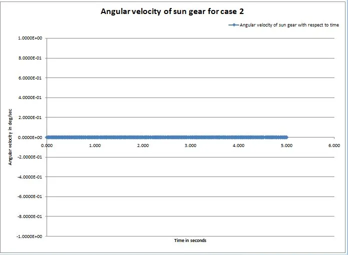
Angular velocity for sun gear :
For case 2, the sun gear is fixed, the remaining gears are floating condition. There is no angular velocity.
Angular velocity for ring gear :
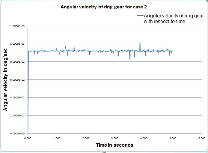
In this case, ring gear is input and it's angular velocity is 1200 deg/sec. It gets power transmitted to planet gear, know planet gear is driven wheel, ring gear is a driver wheel. The gear ratio between ring gear and planet gear is 1.90 times higher than the input speed, but torque has been low.
The input RPM is same as compared to previous case, but the angular velocity is lesser than the previous one, because the radius from axis to outer diameter is long compared to previous case 1.
Angular velocity for planet gear :
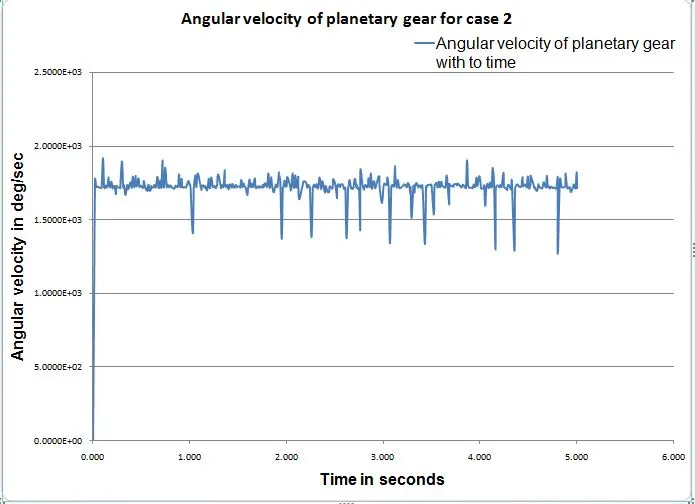
The planet gear angular velocity is 90% higher than the ring gear angular velocity
Angular velocity for Carrier :
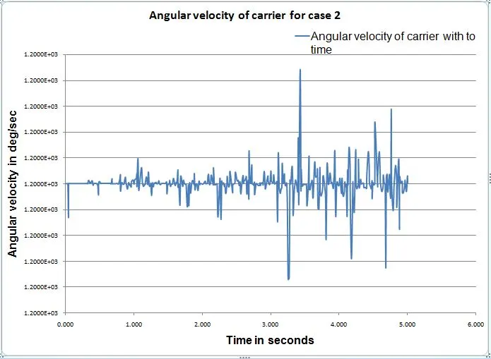
A carrier is output for case 2, the angular velocity is 1200 deg/sec approximately. The speed ratio between planet gear and carrier is 0.68.
Case 3
Carrier is fixed, Sun gear is input & ring gear is Output
Fix the carrier, provide the input speed to sun gear at 200 RPM on clockwise direction. Supress the corresponding concentric circle for four planet gears, it rotates on own axis on counter clockwise direction. The ring gear is rotated on counter clockwise direction.
Youtube link for case 3 : https://www.youtube.com/watch?v=LVeRDPaZ2Qg
Post processing :
Angular velocity of Carrier :
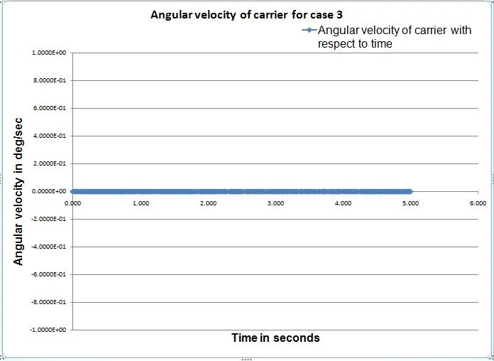
For in this case, the carrier is fixed, the remaining gears are floating condition. There is no angular velocity.
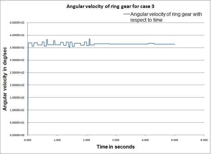
Angular velocity of ring gear :
The angular velocity of ring gear is the output for in this case. It is a reverse gear, we need high torque at low speed. So the speed has been reduced 0.70 times from input speed to output speed.
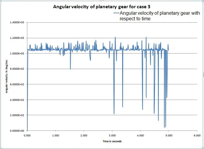
Angular velocity of planet gear :
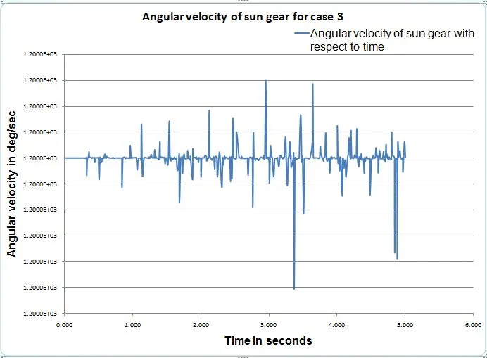
Angular velocity of Sun gear :
A sun gear is input speed at 1200 deg/sec, it is constant over the time period.
OBSERVATION :
| Cases Gears | Ring gear | Sun gear | Planet gear | Carrier |
| Case 1 | 0 (Fixed) | 1200 ( c ) | 520 ( cc ) | 280 ( c ) |
| Case 2 | 920 ( c ) | 0 ( Fixed ) | 1750 ( c ) | 1200 ( c ) |
| Case 3 | 370 ( cc ) | 1200 ( c ) | 1020 ( c ) | 0 |
1) The case 1 and case 2 are forward speed, case 3 is reverse speed. The case 1 act as a low speed transmission, the case 2 act as a high speed forward transmission. The case 3 act as low speed reverse power transmission.
2) The case 1 gear ratio is 0.23, output speed is 0.77 times lesser than the input speed.
3) The case 2 gear ratio is 1.30, output speed is 0.30 times higher than the input speed.
4) The case 3 gear ratio is 0.30, output speed is 0.70 times lesser than the input speed.
CONCLUSION :
To ran the simulation for all different kind of cases had been successfully done with additionally calculated the gear ratio for input speed to output speed.
REFERANCE :
1) https://en.wikipedia.org/wiki/Epicyclic_gearing
2) https://en.wikipedia.org/wiki/List_of_gear_nomenclature
PLANETARY GEAR SYSTEM FILE LINK : https://drive.google.com/drive/folders/1eRmSKz7s0r4QcTopoDphkXUceV06MI_u?usp=sharing