Planetary Gear Systems
PURPOSE:
to impart motion analysis study on system consisting of epicyclic gearing and analyze output results in its various cases of operation
EPICYCLIC GEAR SYSTEM: History and introduction
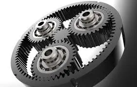
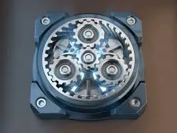
An epicyclic gear train (also known as planetary gear) consists of two gears mounted so that the center of one gear revolves around the center of the other. A carrier connects the centers of the two gears and rotates to carry one gear, called the planet gear or planet pinion, around the other, called the sun gear or sun wheel. The planet and sun gears mesh so that their pitch circles roll without slip. A point on the pitch circle of the planet gear traces an epicycloid curve. In this simplified case, the sun gear is fixed and the planetary gear(s) roll around the sun gear.
An epicyclic gear train can be assembled so the planet gear rolls on the inside of the pitch circle of a fixed, outer gear ring, or ring gear, sometimes called an annular gear. In this case, the curve traced by a point on the pitch circle of the planet is a hypocycloid.
The combination of epicycle gear trains with a planet engaging both a sun gear and a ring gear is called a planetary gear train. In this case, the ring gear is usually fixed and the sun gear is driven.
Epicyclic gears get their name from their earliest application, which was the modeling of the movements of the planets in the heavens. Believing the planets, as everything in the heavens, to be perfect, they could only travel in perfect circles, but their motions as viewed from Earth could not be reconciled with circular motion.
HISTORY:
At around 500 BC, the Greeks invented the idea of epicycles, of circles traveling on the circular orbits. With this theory, Claudius Ptolemy in the Almagest in 148 AD was able to predict planetary orbital paths. The Antikythera Mechanism, circa 80 BC, had gearing which was able to approximate the moon's elliptical path through the heavens, and even to correct for the nine-year precession of that path. (The Greeks would have seen it not as elliptical, but rather as epicyclic motion.)
In the 2nd-century AD treatise Almagest, Ptolemy used rotating deferent and epicycles that form epicyclic gear trains to predict the motions of the planets. Accurate predictions of the movement of the Sun, Moon, and the five planets, Mercury, Venus, Mars, Jupiter, and Saturn, across the sky assumed that each followed a trajectory traced by a point on the planet gear of an epicyclic gear train. This curve is called an epitrochoid.
Epicyclic gearing was used in the Antikythera Mechanism, circa 80 BC, to adjust the displayed position of the moon for the ellipticity of its orbit, and even for the apsidal precession of its orbit. Two facing gears were rotated around slightly different centers, and one drove the other not with meshed teeth but with a pin inserted into a slot on the second. As the slot drove the second gear, the radius of driving would change, thus invoking a speeding up and slowing down of the driven gear in each revolution.
USAGE AND APPLICATION:
- automatic transmission in vehicles
- robotics, electrical vehicle drives, 3D printer spindle drives
- Backgauge drive for press brakes
- Axis drive for laser cutting machines
- Angle gearbox for rotary tables
- Height adjustment of operating tables
MOTION STUDY ANALYSIS:
GEAR PARAMETERS:
1) SUN GEAR :
- Number of teeth(T) = 14
- Input Speed of the Gear(N) = 200 rpm.
- Module(m) = 2.5
- material : steel (grease applied)
- nominal shaft diameter = 15 mm
- hub diameter = 22 mm
- hub length = 30 mm
- gear width = 20 mm
- number of keyways = 1
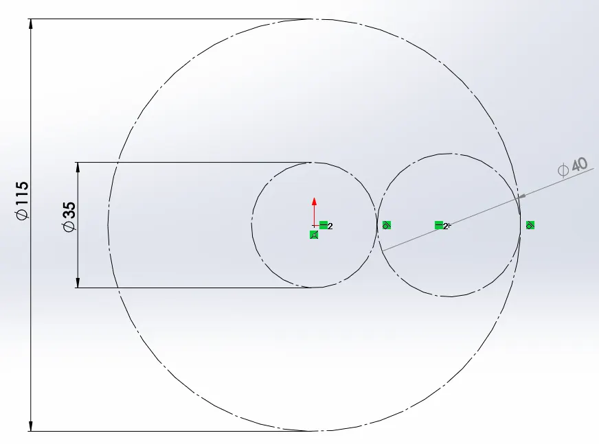
hence, pitch circle diameter(p) = m * T = 2.5 * 14 = 35 mm
2) RING GEAR:
- Module = 2.5
- Number of teeth = 46
- Input Speed of the Gear(N) = 200 rpm.
- material : steel (grease applied)
- gear width = 30 mm
- outer hub width = 50 mm
- gear diameter = 150 mm
- hub diameter = 170 mm
- spline teeth heigth = 5 mm
- number of splines = 12
hence, pitch circle diameter(p) = m * T = 2.5 * 46 = 115 mm
3) PLANETARY GEAR:
- Module = 2.5
- material : steel (grease applied)
- nominal shaft diameter = 15 mm
- gear width = 30 mm
- number of gear = 4
here,
pitch circle diameter of planet gear = (p.c.d of ring gear - p.c.d of sung gear) / 2
= ( 115 - 35 )/2 = 40 mm
and, number of teeh = 40 / 2.5 = 16
ASSEMBLY AND MODEL GEOMETRY:
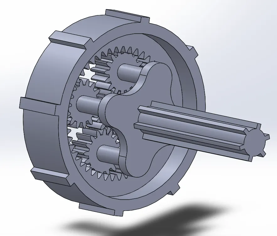
FILES ( CAD MODELS AND ASSEMBLY):
https://drive.google.com/drive/folders/12lpnjDSxaSp_XP4UWDT_yxvLLBnMIsGM?usp=sharing
RELATION BETWEEN ANGULAR VELOCITY (deg/sec) AND RPM (rev. per minute):
N rpm = N * 360 / 60 = 6N deg/second
CASE 1:
INPUT: SUN GAER, OUTPUT: CARRIER, FIXED: RING GEAR
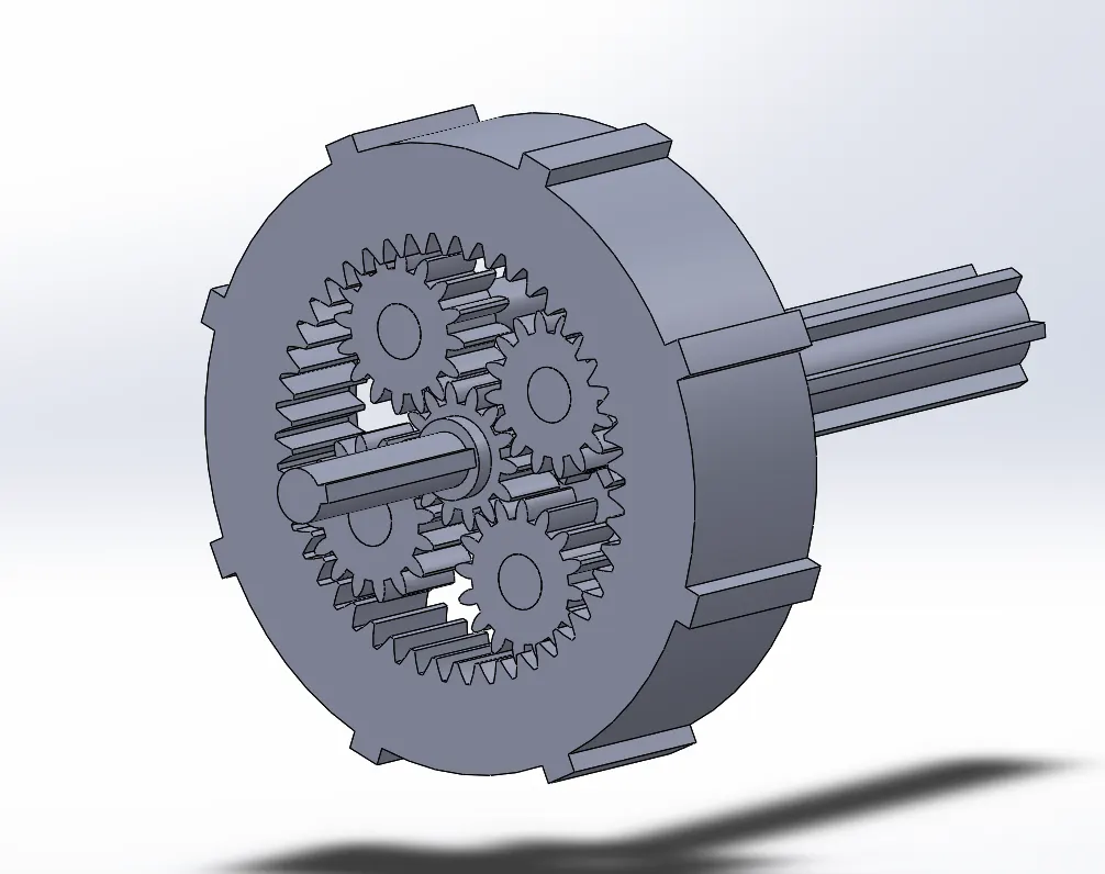
in this case, the motor is connected with power shaft which drives the sun gear with rotational speed of 200 rpm. the power is transmitted to planetary gears and further to the carrier.
the main shaft of the carrier has spined teeth to be coupled with any device to transmit power to.
ring gear in this entire study setup is kept fixed which provides structure to the setup in this case.
video link: https://youtu.be/QBDPQoO606A
RESULTS AND DISCUSSION :
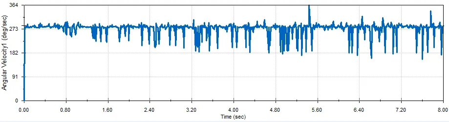
by observing the angular velocity of the carrier part, we realize that the value is oscillating for short times and fluctuates between 182 deg/sec to 364 deg/sec with a mean velocity of 273 deg/sec. whereas the input speed of motor is 200 rpm = 1200 deg/sec. hence speed reduction is done in such arrangement.
the jerks represent gap tolerances, and the impact of sun gear for very small time with planet gear is responsible for the fluctuations observed in results.
with precise tolerances and more accurate calculations, we can further ''smoothen'' the curve to around the mean line of 273 deg/sec.
MANUAL CALCULATIONS:
here we'll try to gain some insight by manual calculations and, will counter check the results we've obtained so far.
we know that the linear velocity at pitch circle diameter (the place at which actual contact/meshing occurs) for both the mating gears are the same, hence using that knowledge we'll be able to predict the theoretical angular speeds of the output gears.
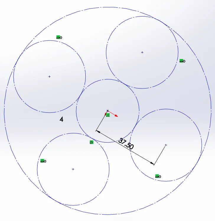
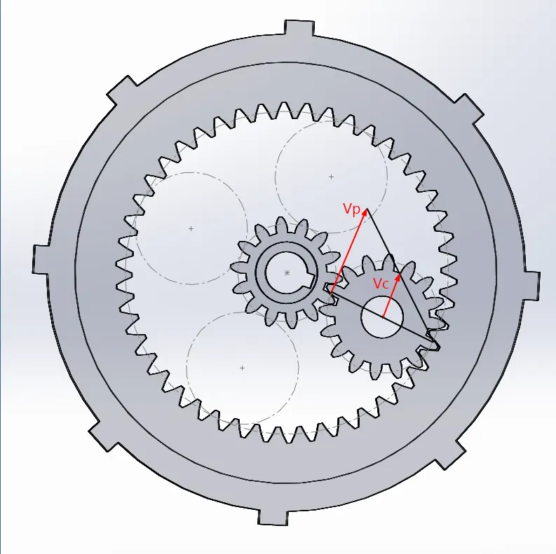
from the figure, the peripheral velocity at pitch circle diameter of sun gear is:
Vp = Rs * Ws , where Rs = radius of sun gear & Ws = angular speed of sun gear.
for planet gear, this velocity will drive planet gear on the axis of ring gear with the velocity at center of mass Vc as well as about its own axis.
from the kinematics of machine, we know that point of contact between planet gear and stationary ring gear acts as an instantaneous center of planet gear and the velocity Vc is exactly half that of Vp.
hence, peripheral velocity Vc = Rc * Wc = Vp / 2. where Rc is a distance of the center of planet gear from the main axis of the assembly.
hence, the angular speed of carrier :
Wc = Vp / 2Rc
= Rs * Ws / 2Rc
= 17.5 * 1200 / (2*37.5) ( 200 rpm = 1200 deg/sec )
= 280 deg/sec
comparing this velocity with a mean angular velocity of results which is 273 deg/sec suggests that the results are correct simulation wise; with small allowances for gap tolerance.
CASE 2:
INPUT: RING GEAR, OUTPUT: CARRIER, FIXED: SUN GEAR
in this study, the power is expected to transmit via external agent to the ring gear. the spline teeths on ring gear hub deliver motion to ring gear and further rotates planetary gear and carrier mechanism.
sun gear in this entire setup is fixed and provides a structure for this mechanism. power shaft stays idle in this arrangement.
note: structure is referred to as a component with a degree of freedom zero.
video link: //www.youtube.com/embed/WL-nzG7QgrU
RESULTS AND DISCUSSION :
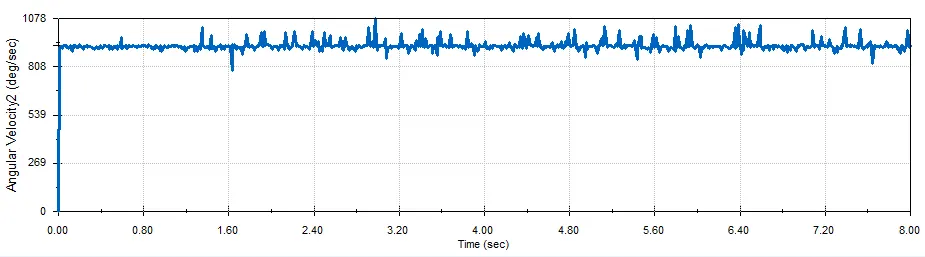
here. the carrier rotates with higher angular velocity compared to previous study. the speed is almost averaged at 900 deg/sec and is nearly 3.5 times more than previous speed achieved by the carrier.
the input angular speed of ring gear is the same as of 1200 deg/sec. the higher angular speed of carrier is due to larger peripheral linear velocity at pitch circle diameter. here, the linear velocity contributes to rotate planetary gear along its axis as well as the axis of the ring gear.
MANUAL CALCULATIONS:
by observing the figure given below, the situation is pretty much the same as the previous one, with only difference here being the peripheral velocity of ring gear. the distance of center of planatary gear from the main axis is still the same as of 37.5 mm which, ultimately, is the peripheral velocity of the shaft center of the carrier.
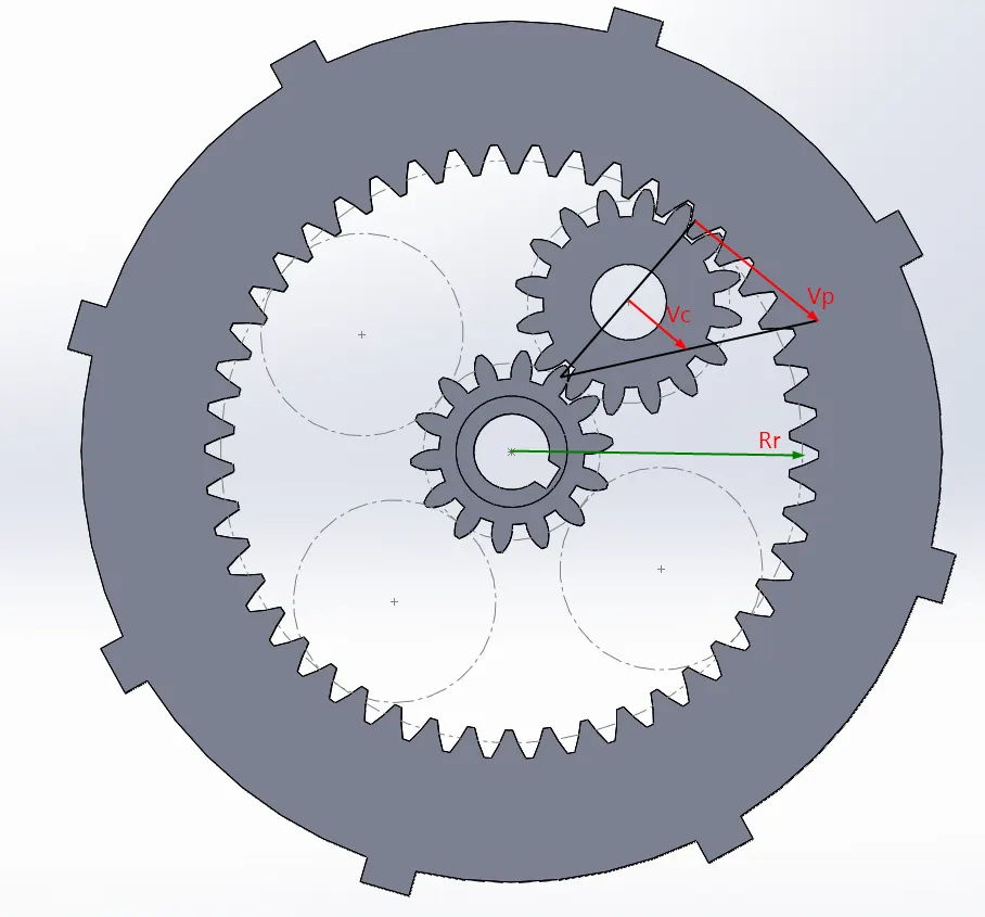
hence,
Wc = Vp / 2Rc
= Rr * Wr / 2Rc
= 57.5 * 1200 / (2*37.5) ( 200 rpm = 1200 deg/sec )
= 920 deg/sec
which again, corresponds to the simulated angular speed of the carrier around 900 deg/sec.
CASE 3:
INPUT: SUN GAER, OUTPUT: RING GEAR, FIXED: CARRIER
this case illustrates the mechanism in which carrier is being fixed and the power transmitted by power shaft to the sun gear is delivered to the planetary gears which are free to rotate about their own axis but not about axis of the main assembly i.e. carrier axis.
these planetary gears further rotate ring gear and power is delivered via spline teeth located on the hub of the ring gear.
RESULTS AND DISCUSSION :
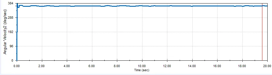
the output angular speed of the ring is around 350 deg/sec and seems to be pretty constants with almost no jerks and fluctuations.
however, smooth harmonic fluctuations are observed at some parts related to the impacts of gear teeth within the assembly.
MANUAL CALCULATIONS:
this case is fairly simple to calculate because in this scenario, carrier is fixed and entire peripheral velocity is utilized in rational motion everywhere.
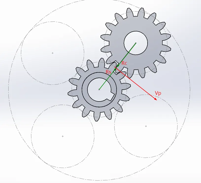
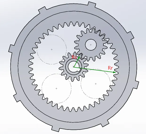
the value of the peripheral velocity at all pitch circle diameters are same.
hence,
Vp = Rs * Ws = Rc * Wc = Rr * Wr
therefore:
Wr = Rs * Ws / Rr
= 17.5 * 1200 / 57.5
~= 365 deg/sec
which is consistent with the simulation result of angular speed around 350 deg/secod