Buckling analysis on connecting rod of Suzuki 2.0 L spark-ignition engine
INRODUCTION:
The connecting rod is the transitional part between the piston and the crankshaft. Its essential capacity is to transmit the push and pull from the piston pin to the crank pin, in this way changing over the reciprocating motion of the cylinder into turning movement of the crank. The capacity of connecting rod is to transmit the push of the piston to the crank shaft, and as the outcome the reciprocating motion of the piston is interpreted into rotational movement of the wrench shaft. It comprises of a pin–end, a shank section and a crank end. Pin end and crank end pin holes are machined to allow exact fitting of bearings. In this project, a connecting rod is demonstrated utilizing solidworks and analysis utilizing ansys workbench. The outcome predicts the most extreme buckling load and basic locale on the interfacing pole. It is imperative to find the basic territory of concentrated stress for fitting adjustments. To discover the stresses created in interfacing pole under static loading with various stacking states of compression and tension at crank end and pin end of connecting rod.
To appreciate the certifiable impact, the vehicles had on our overall population, we would need to turn around in time more than one hundred years. A period without the ease of hopping into a vehicle to take us wherever we have to go is skirting on difficult to various Americans. Nevertheless, for the early auto constructs, the gigantic degrees of progress in auto development would be significantly all the all the more shocking.
In this project, one segment of a motor specifically, the connecting rod, will be broke down. Being a champion amongst the most vital parts in an engine's diagram, the interfacing pole must have the ability to withstand immense loads and transmit a considerable measure of force. It is nothing sudden that a failure in an associating bar can be one of the costliest and hurting frustrations in an engine. Regardless, fundamentally saying that isn't adequate to totally fathom the elements of the situation.
INRODUCTION TO BUCKLING:
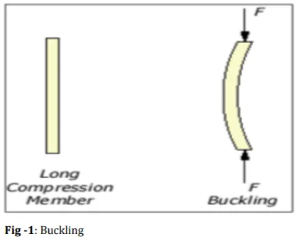
Buckling is the instable phenomenon. The buckling happens only at one load, and that load is called as critical buckling load which is given by Euler formula Pcr = π2EI/ le for columns as shown in fig 1.
Where,
E- Young’s modulus
I-Moment of Inertia
Le-Effective length of the column
When the maximum stress of the structure is less than ultimate strength and it is said to be safe, at that time critical buckling load becomes design driver i.e. if the applied load is greater than the critical buckling load, the structure will fail even though it is designed with respect to its strength.
The ratio of critical buckling load to applied load is called as Buckling Factor (B.F) which is used to know whether the structure is buckled or not
OBJECTIVE:
The objective of this study is to, Determine the total stress developed on the connecting rod due to the force applied on the connecting rod from the power stroke of a Spark-ignition engine. And also to study the effects of buckling load of the same magnitude as that of the power stroke applied on the connecting rod from the power stroke of a Spark-ignition engine.
METHODOLOGY:
1.) Geometry of a connecting rod will be modeled using modeling software (solidworks).
2.) The Generated CAD Model is then discretized and a Finite Element Model will be created using a PreProcessor .
3.)The loads and boundary conditions that were calculated will be applied on the FE Model during Pre-Processing.
4.)The generated solver deck is fed to a solver (workbench) Post-processing of the results obtained are performed with Post-processor.
FINEITE ELEMENT ANALYSIS:
In this project, the geometry of the connecting rod, Mesh generation and the analysis components are discussed. The load calculation to determine the buckling load has also been shown in this project work.
1.)Geometric Modeling:
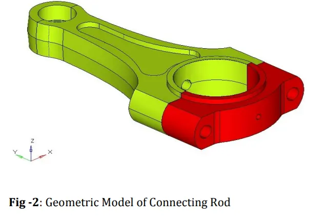
The above figure demonstrates the geometric model of an associating pole utilized as a part of a two-chamber SI Engine. It contains a cylinder end, shank and a wrench end isolated into two sections for less demanding establishment. For model rearrangements, all filets and chamfers underneath 3mm are disregarded and the last model is spoken to in the above figure. The shank is an I-area of differing segment with the littler end at the cylinder end and the bigger segment at the wrench end.
2.) FE Modeling:
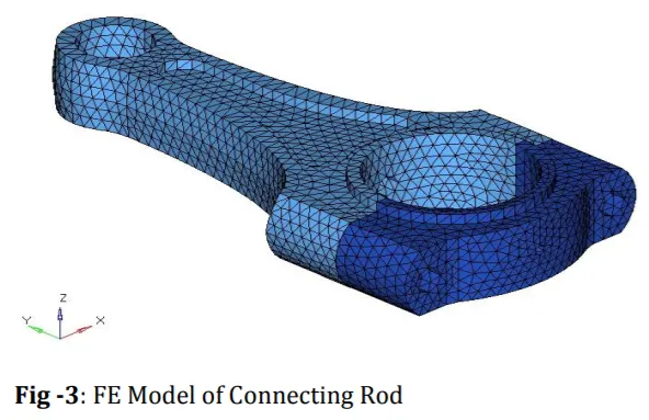
The geometric model shown in the previous section is discretized using tetrahedral elements. These elements are selected because of their ability to capture the geometry of any complex model. Since this model is of various shapes and sizes, a tetra element of the first order is selected. The crank was divided into two components in the geometric model and the same has been maintained in the FE model also.
3.) Loads and Boundary Conditions:
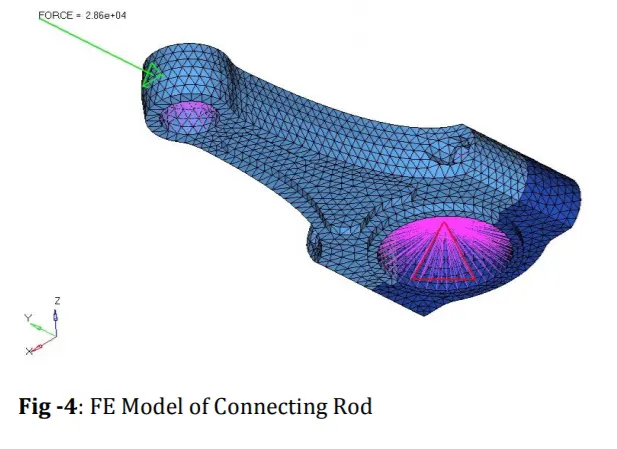
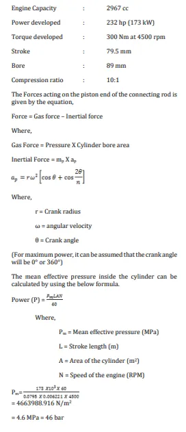
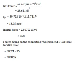
Figure 4 shows the discretized model with loads and boundary conditions applied. For this investigation, the interfacing pole is set at the top right on target amid the beginning of the force stroke. Thus, the wrench is obliged in all degrees of opportunity and the heap is connected on the cylinder end of the associating pole. The estimations identifying with the heap connected is demonstrated as follows.
3.) Engine Specification:
RESULTS:
The analysis was run for the above mentioned FE Model with the loads and boundary conditions attached to it. The following figures give the results obtained from both the static analysis (Displacement and Stresses) and buckling analysis (Buckling mode).
1.)Static Analysis:
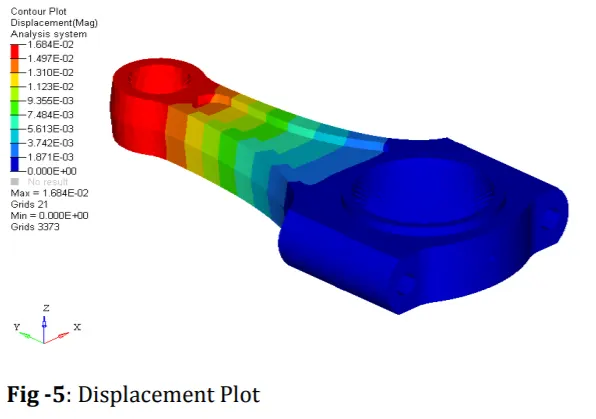
Figure 5 above shows the displacement for the selected connecting rod under the loads applied. It is clear from the above figure that the maximum displacement occurs on the piston end at a value of 0.176 mm and minimum displacement occurs on the crank end at a value of 0 mm.
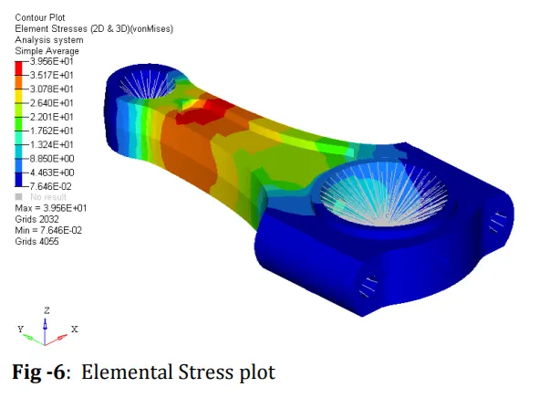
Figure 6 above shows the Von Mises stress plot for the selected connecting rod under the loads applied. It is clear from the above figure that the shank is subjected to a maximum stress near the piston end at a value of 414.34 MPa. This value is very much less than the yield strength of the material and hence it can0be said that the0connecting rod is safe under the applied0load because the value of the stress developed is well within the maximum allowable stress level of 468.85 MPa. This value is obtained by considering a factor of safety of 2 for forged steel which has the ultimate strength of 937.7 MPa.
2.)Buckling Analysis:
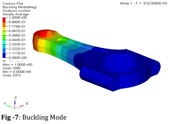
Figure 7 shows the buckling mode plot of the connecting rod for the applied loads. It is observed that the buckling factor is 86.23 which means that the connecting rod designed can withstand loads as high as 86 times the load applied.
CONCLUSION:
From the results it can be concluded that,
1.) The displacement plot shows a very small value which does not affect the performance of the connecting rod.
2.) The linear static analysis of the connecting rod shows that the stress generated in the model is within the acceptable limits or maximum allowable stress.
3.) The buckling mode analysis gives the buckling factor greater than 1 and hence it can be concluded that the connecting rod can withstand the load applied.