Planetary Gear
AIM:
To analyse the motion of different gear components in a Planetary Gear Arrangement by performing a Motion Analysis in SolidWorks.
INTRODUCTION AND THEORY:
A Planetary Gear or Epicyclic Gear Train consists of three gears: one internal gear and two external gears. The internal gear is the largest in size called ring Gear. The gear at the centre is called sun Gear. The gear that revolves around the sun gear is called planet Gear. The planet gear is connected to a carrier which transmits the power. This type of gear arrangement is used in automatic transmission vehicles.
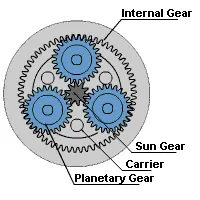
DATA GIVEN:
- Ring Gear
- Module = 2.5
- Number of teeth = 46
- Sun Gear
- Number of teeth = 14
- Input Speed of the Gear = 200 rpm.
- Number of planet gears = 4
DATA CALCULATED:
Radius of Ring Gear = Radius of Sun Gear + (2*Radius of Planet Gear) .
1. Diameter of ring gear = module * number of teeth = 2.5 * 46 = 115 mm.
2. Diameter of Sun Gear = module * number of teeth = 2.5 * 14 = 35 mm.
Therefore, Diameter of planet gear = Radius of Ring Gear - Radius of Sun Gear = (115/2) - (35/2) = 40 mm .
Number of teeth in planet gear = 40/2.5 = 16.
Note: All these diameter values correspond to Pitch Circle Diameter.
OTHER DESIGN DATA:
Planet gear shaft diameter = 15 mm
Sun gear shaft diameter = 20 mm
DESIGN MODELS:
Ring Gear:
Sun Gear:
Planet Gear:
Carrier:
Planetary Gear Assembly:
EXPLANATION:
The basic principle is ratio of the speeds of gears meshed is inversely proportional to the number of teeth of the gears meshed.
The Motion Analysis is done for the above three cases.
- The gears are available as templates in SolidWorks where parameters like module, number of teeth etc., are specified as per the input data.
- Each gear is brought to SolidWorks workspace in an assembly file.
- Necessary mates are given between different gear components to form a planetary gear arrangement.
- Once the arrangement is done, different gears are fixed according to the above three cases.
- Motion Analysis parameters are set. The frames per second is set to 7200 fps.
- Precise contact is used.
- Then output is obtained for the given input.
RESULTS:
CASE 1:
As can be seen from the plot, the angular velocity of carrier is almost constant. The slight deviation in the angular velocity may be due to slight free movement in gear meshing.
CASE 2:
As can be seen from the plot, the angular velocity of carrier remains nearly constant.
CASE 3:
As can be seen from the plot, the angular velocity of ring gear is almost constant.
In all the three cases, the angular velocity output is almost constant. This is very essential because otherwise the gears would get damaged in fatigue mode if a gear that gives output runs at different speeds for the same input at any gear.
CONCLUSION:
Hence the motion analysis is performed for the planetary gear arrangement.