Photo Realistic Rendering
Rahul_CHOPPER : https://drive.google.com/drive/folders/1OlZtFqlsgFY_zi2JYggHHWbgr1BPgU_a?usp=sharing
DESIGNING AND ASSEMBLING OF AMERICAN CHOPPER USING SOLIDWORKS
Introduction:
The new world’s competitive market-driven economy CAD/CAM industry has grown to be one of the sought after industries. 3D Modelling gives so many advantages in the design process. It can save expensive and time-consuming experimentation and rework to finalize the design. SolidWorks is one of those 3D modeling tools which is recognized all around the globe. It is a parametric feature-based solid modeling tool. it is one of the easiest 3D modeling software to learn.
Here, by using various tools in the SolidWorks the American Chopper model is designed, modeled, and rendered. The American Chopper was manufactured by the Orange County Choppers based out of Orange County, New York during the late 1990s and early 2000s. These motorcycles received attention mainly because of their themes, where these motorcycles are specifically built for the customer's dimensions and liking. By using the SolidWorks tools the 3D model of the chopper is created which includes surface geometry, mirror features, patterns, etc.,
Objectives:
- To model the parts of the American Chopper using SolidWorks.
- To assemble the created parts using SolidWorks.
- To create a photo-realistic rendering using Photoview 360 and Visualize.
Softwares Used:
- SolidWorks 2020.
- PhotoView 360 (Add-in).
- Solidworks Visualize 2020.
American Chopper Parts:
- Transmission belt.
- Kick Stand.
- Front fender.
- Rear fender.
- Oil tank.
- Pedal.
- Chain.
- Front-wheel (inclusive of the tire, Brake disc, brake caliper).
- Rear-wheel (inclusive of the tire, brake disc, brake caliper, chain sprocket).
- Front fork.
- Chassis.
- Engine.
- Gas tank.
Modeling of American Chopper Parts:
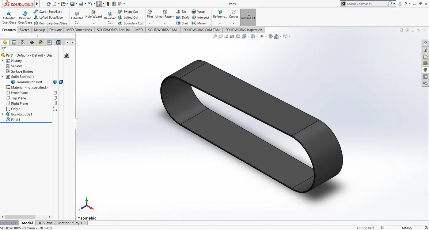
1). Transmission belt:
A belt is a loop of flexible material used to link two rotating shafts mechanically to transmit power from one shaft to another. Pulleys are used to hold the belt aligned. The belt is the cheapest utility for power transmission. They are usually made up of rubber material. They have an efficiency of 90 - 98%. In this American chopper model, a flat transmission belt is used to transmit power from the crankshaft to the transmission unit.
2). Kickstand.
The kickstand is a part of the motorcycle that allows the motorcycle to be kept upright without the need of a person to hold them or other external sources. It is a piece of metal that can be flipped down from the chassis and makes contact with the ground.
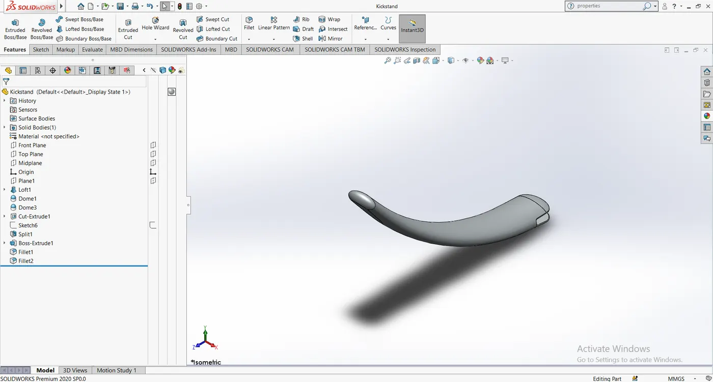
Commands used: Sketch, Loft extrude, Boss-extrude, cut-extrude, dome, fillet.
3). Front fender and rear fender:
The fenders in motorcycle cover over the top portion and some back portions of the wheel. The purpose of these fenders is to prevent the sand, mud, water, and other particles that may be present in the road to be thrown in the air and which eventually hits the rider and other riders on the road.
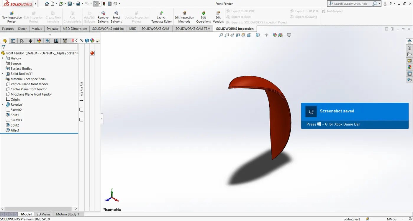
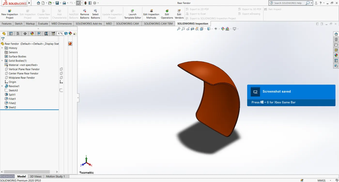
Commands used: Revolve extrude, fillet, split, sketch, shell.
4). Oil Tank:
The oil tank in the motorcycle contains the essential lubricant for the engine and the transmission system to perform smoothly. It is typically located in a position safe from being hit easily.
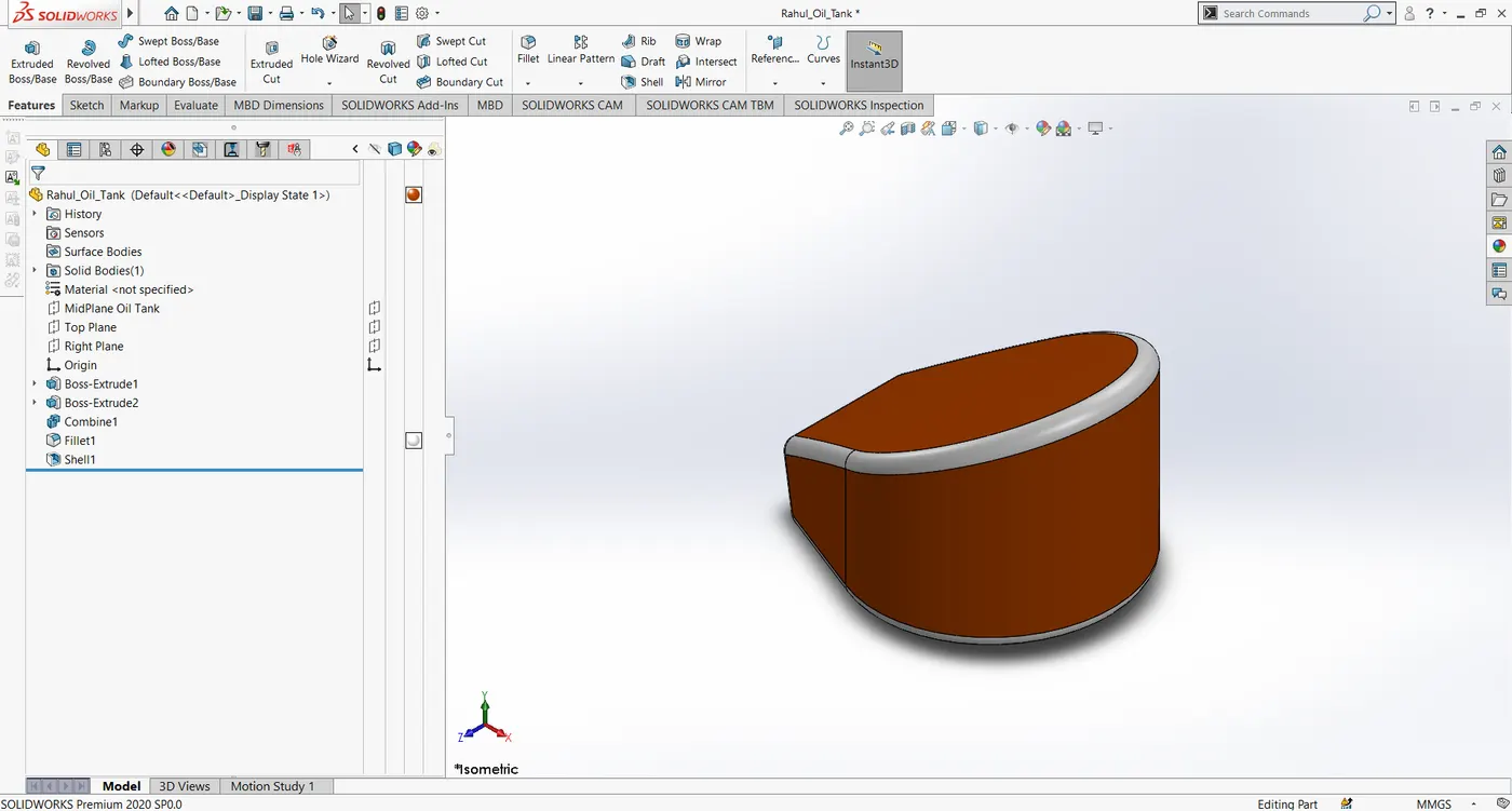
Commands used: Sketch, boss-extrude, combine, shell, fillet, split.
5). Pedal
The pedal is attached to the chassis of the motorcycle. The pedal acts as a footrest to the rider, in many motorcycles the pedal also houses' a link for actuating brakes.
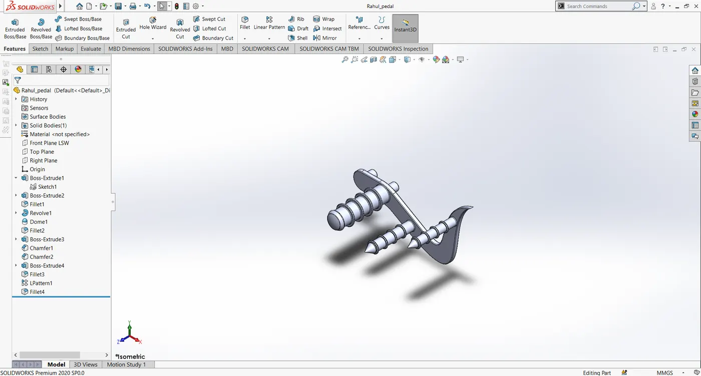
Commands used: Sketch, boss-extrude, revolve, chamfer, fillet, dome, linear pattern.
6). Chain:
Like a belt, the chain is used to transmit power from one shaft to another. The chain is connected to shafts by using sprocket gears. In this motorcycle, the chain drive is used to transmit power from the transmission unit to the rear wheel of the motorcycle. The chain drives are mainly used to transmit power to the wheels of bicycles and motorcycles.
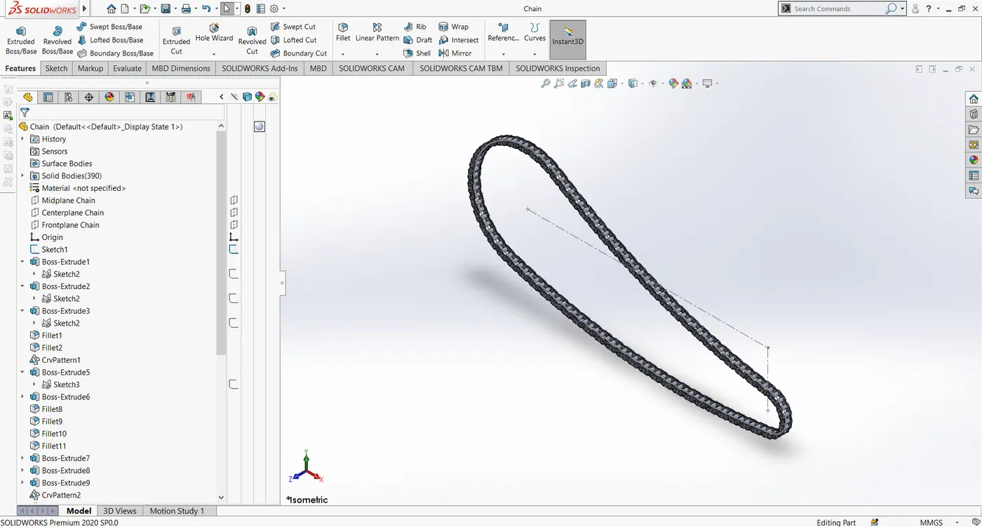
Commands used: Sketch, blocks, boss-extrude, curve-driven pattern, fillet.
7). Front-wheel and rear wheel:
The components such as wheel rim, tire, brake disc, brake caliper, and sprocket wheel essentially make a wheel in a motorcycle.
The brake disc, caliper, sprocket wheel are attached to the wheel by means of provisions provided for attachment.
The wheels are what makes the vehicles to roll over the roads at low to high speeds, so they are made in such a way to withstand stresses of axial and radial direction.
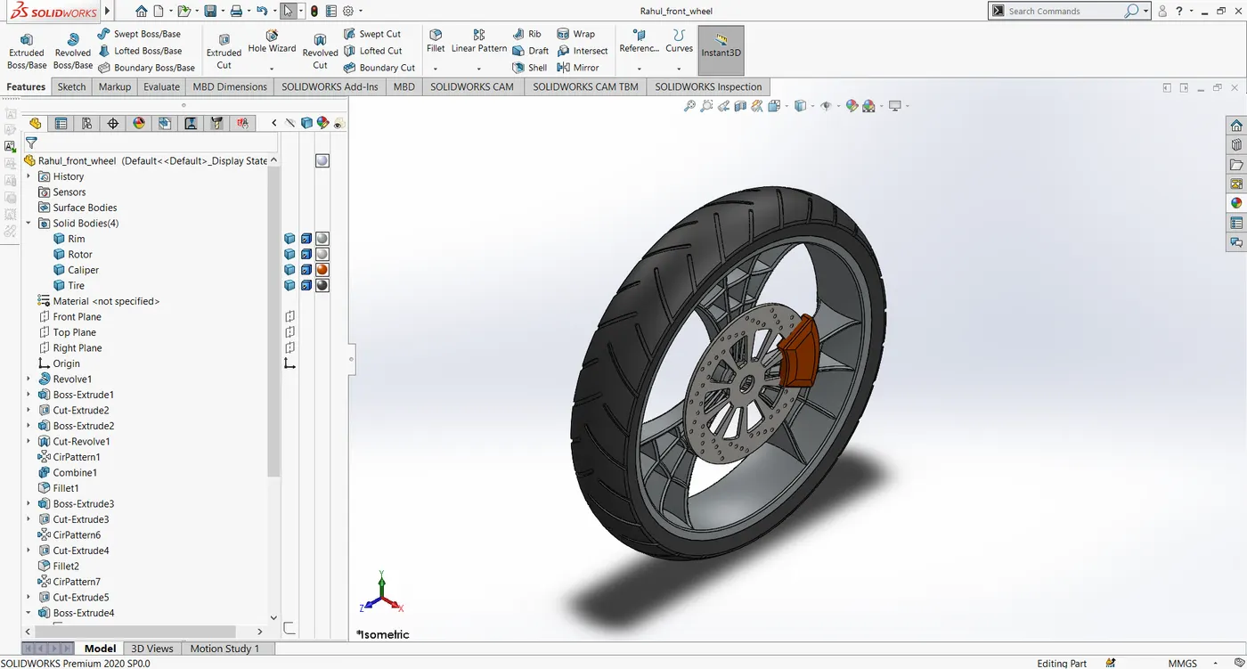
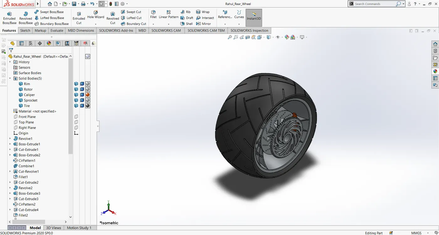
Commands used: Sketch, Revolve-extrude, Boss-extrude, cut-extrude, circular pattern, chamfer, fillet, combine.
8). Front fork:
The front fork connects the front wheel and the chassis. The front fork allows the vehicles to be steered in a particular direction. The front fork also houses the headlights, the brake levers, and accelerator in its handle.
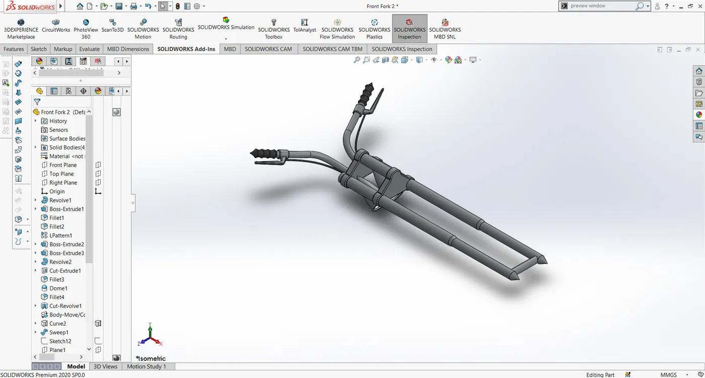
Commands used: Sketch, Boss-extrude, Cut-extrude, Curves, linear pattern, chamfer, fillet, combine, move-body, mirror, sweep.
9). Chassis:
The chassis is basically the skeleton of the motorcycle upon which various components are mounted. The chassis is made up of hollow tubes of steel or other alloys. it also has provisions for attaching the components such as the engine, gas tank, front fork, wheels, etc..
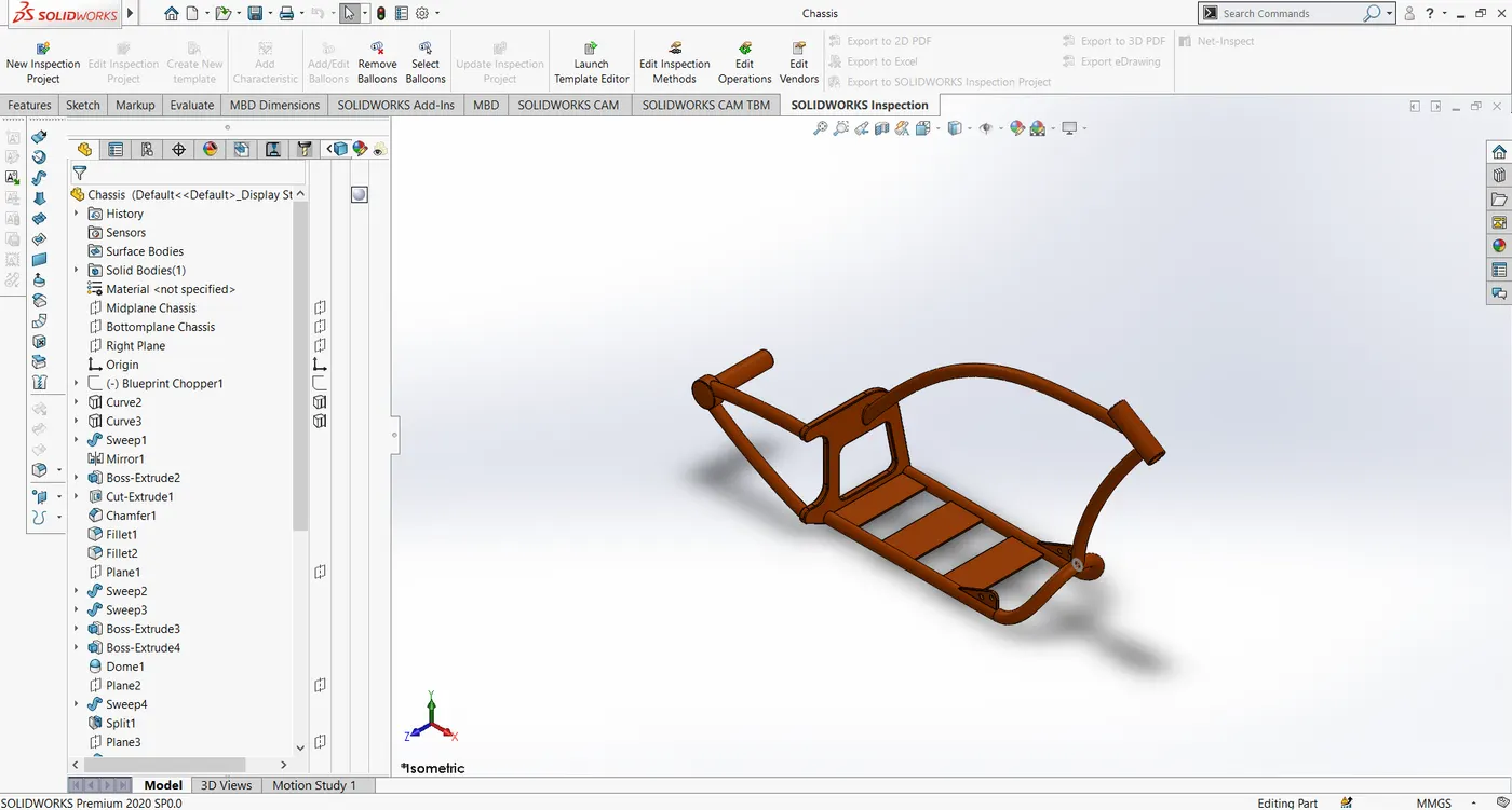
Commands used: Sketch, Boss-extrude, cut-extrude, curves, dome, fillet, chamfer, split, mirror, combine.
10). Engine:
The engine is the heart of the motorcycle, which powers the motorcycle by burning fuel. The energy produced is translated into mechanical energy by means of the crankshaft and the transmission unit. The motorcycle engines are typically two-stroke and four-stroke Engines.
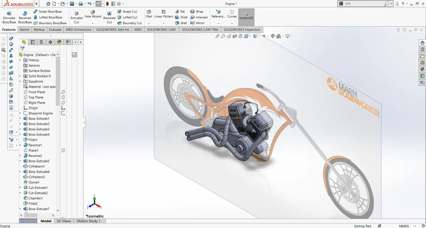
Commands used: Sketch, Boss-extrude, Cut-extrude, sweep, revolve, curves, fillet, chamfer, chamfer, dome, split, combine, mirror, linear pattern.
11). Gas tank:
The gas tank is used to store the fuel needed to power the engine. The gas tank usually sits atop the motorcycle. It is made of a strong material that can withstand a moderate collision without splitting.
The gas tank is created by using the surface modeling tools available in the SolidWorks
The individual parts saved in SolidWorks have the file extension of .SLDPRT.
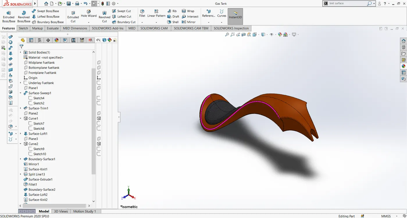
Commands used: Sketch, Surface sweep, Surface trim, Surface loft, boundary surface, fill surface, surface knit, curves, fillet, a split line, mirror, sweep cut, shell.
Assembly of the American Chopper:
The components of the American chopper that was modeled can be assembled together to make the complete American Chopper can be done in the Assembly section of the Solidworks. In the assembly window, all the components can be inserted to form a single assembly, or small sub-assemblies can be created, and then that can be inserted. There are various mates available in the SolidWorks from standard mates such as coincident, parallel, distance mates, concentric, to advanced mates such as gear mates, width mates, etc.
The assembly file has the extension of .SLDASM.
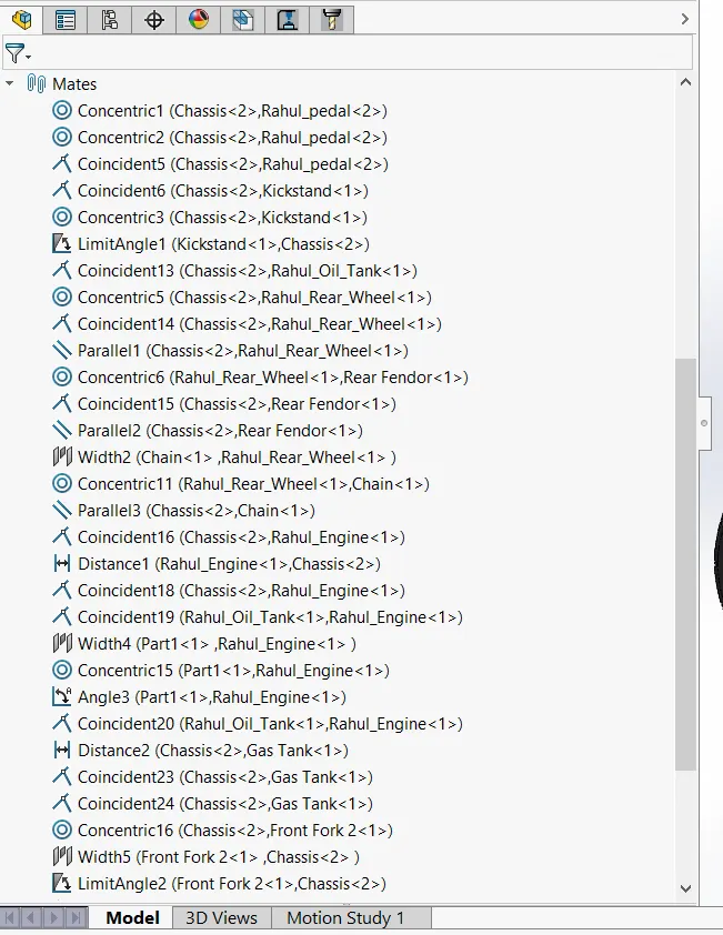
The mates used include : Coincident, parallel, distance, concentric, width, angle, tangent.
Rendering the American Chopper:
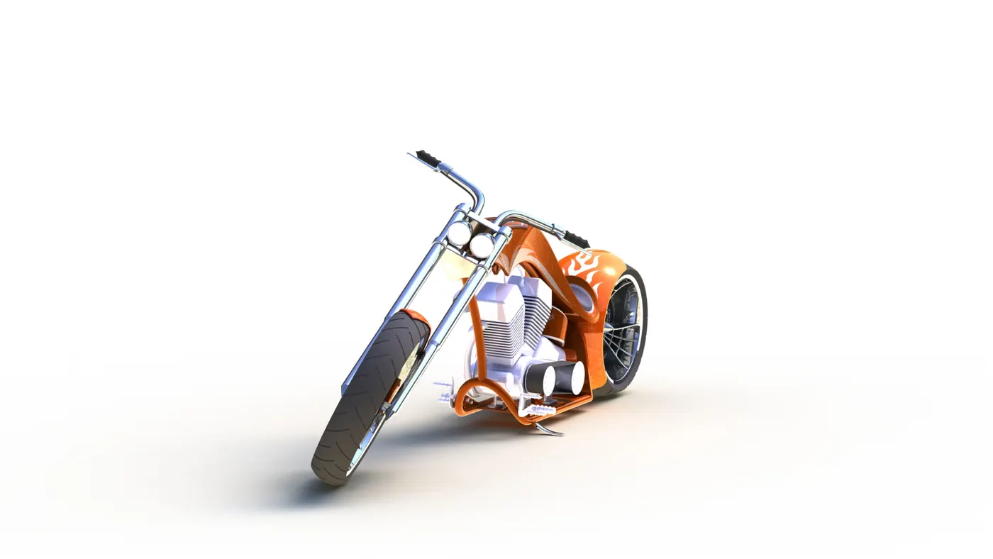
After assembling the model we need to give a realistic look to have an idea about how it looks in the real world, to make it look real there are rendering tools available in the Solidworks such as PhotoView360 and SolidWorks Visualize. The Photoview 360 is an add-in available in the Solidworks. The Solidworks Visualize is a standalone rendering software to make realistic renderings.
Before making the rendering process the decals are added to the model, the choppers are known for their theme.
The decals, suitable colors are added.
The camera is added for the rendering process in addition to the available standard views, adding a camera gives a nice perspective on how it looks in the real world.
After adding the camera the background scenes are edited and suitable lights are given in the PhotoView 360 add-in.
After that, a preview render is generated to make sure the render would look good, after that a final render is made on each view.
Solidworks Visualize:
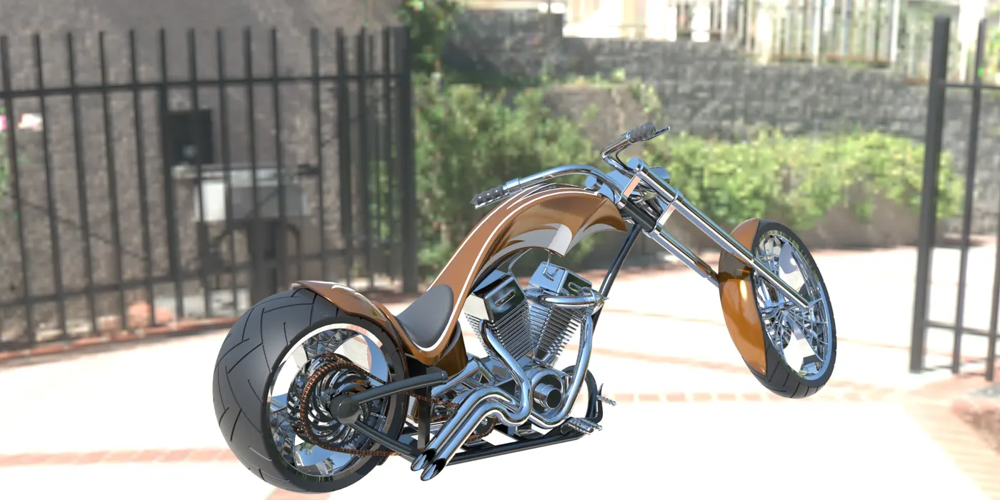
The SolidWorks visualize has a lot of rendering tools available. In this software, many features like backplates, HDR environments, Cameras, Scenes, Appearances have many additional to that of photo view 360 features. it is capable of creating high quality renders.
The projects created with SolidWorks have the extension of .SVPJ
Conclusion:
The American Chopper model is thus created by using the various tools available in the SolidWorks and the photo-realistic renders are created using the SolidWorks Visualize Software.