Assembly of Yacht
Rahul_Radarmast : https://drive.google.com/drive/folders/1DsHXnqIrn4pUIor2MoYgSu1_QGHj42CN?usp=sharing
Rahul_Yacht : https://drive.google.com/file/d/1UqUaTPgSsw5DWFZWqdo0y9X_t8eAl3re/view?usp=sharing
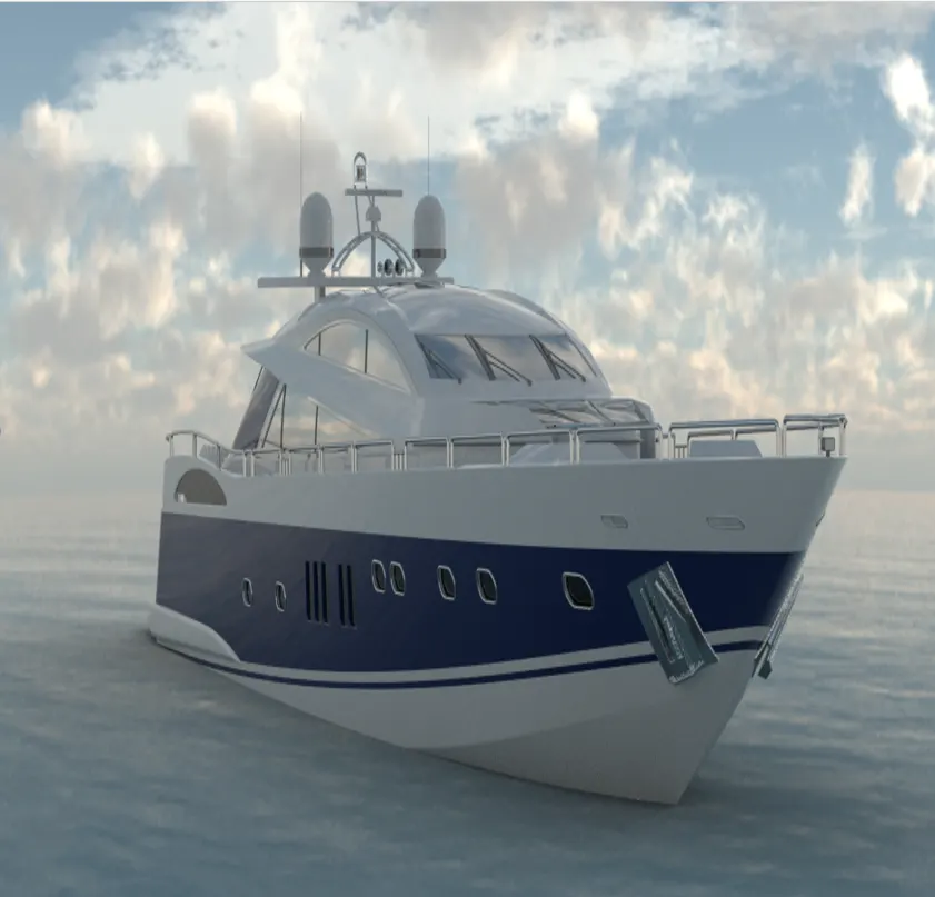
SUNSEEKER PREDATOR YACHT
Objective:
- To model the parts of the Sunseeker Predator Yacht using SolidWorks.
- To assemble the created parts using SolidWorks.
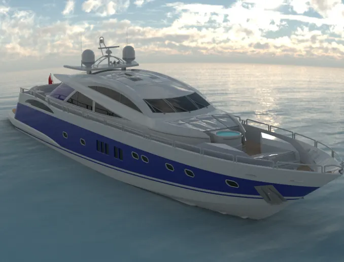
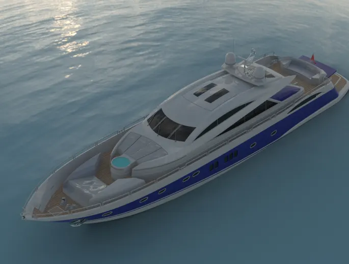
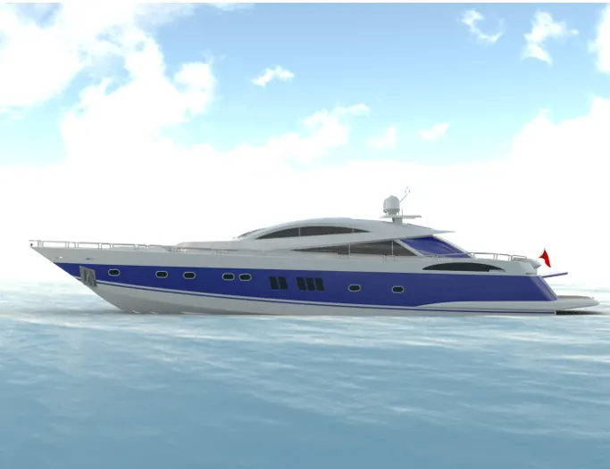
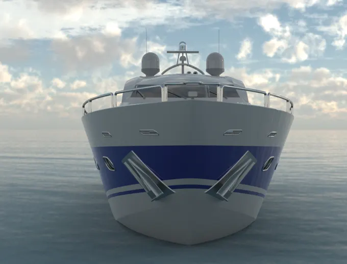
- To create a photo-realistic rendering using Photoview 360 and Visualize.
Introduction:
In today's competitive market-driven economy the CAD/CAM industry has grown to be one of the sought after industries. 3D Modelling gives so many advantages in the design process. It can save expensive and time-consuming experimentation and rework to finalize the design. SolidWorks is one of those 3D modeling tools which is recognized all around the globe. It is a parametric feature-based solid modeling tool. it is one of the easiest 3D modeling software to learn.
Here for creating a Yacht model the various solid and surface modeling tools in SolidWorks are used. The surface tools are majorly used. This modeled predator yacht is manufactured by the Sunseeker International a UK based luxury Yacht manufacturer. By using various surface tools and other solid modeling tools the model of the predator yacht is recreated and it is then rendered to give a photorealistic appearance.
Softwares Used:
- SolidWorks 2020.
- PhotoView 360 (Add-in).
- Solidworks Visualize 2020.
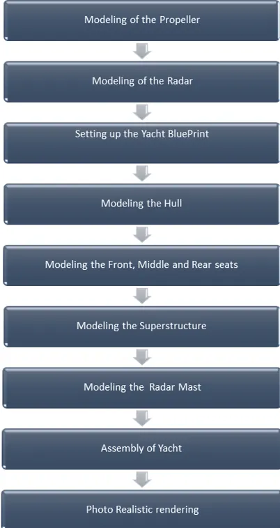
Yacht parts modeled:
- Propeller.
- Radar.
- Hull.
- Garage Door.
- Superstructure.
- Front, middle and rear seats.
- Radar Mast.
Design approach:
Designing the Yacht parts:
- Propeller:
A propeller is a rotating fan-like structure that is used to propel the ship by using the power generated and transmitted by the main engine of the ship. The transmitted power is converted from rotational motion to generate a thrust which imparts momentum to the water, resulting in a force that acts on the ship and pushes it forward.
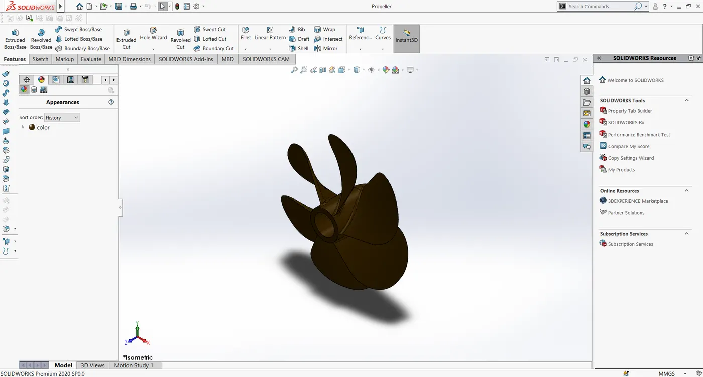
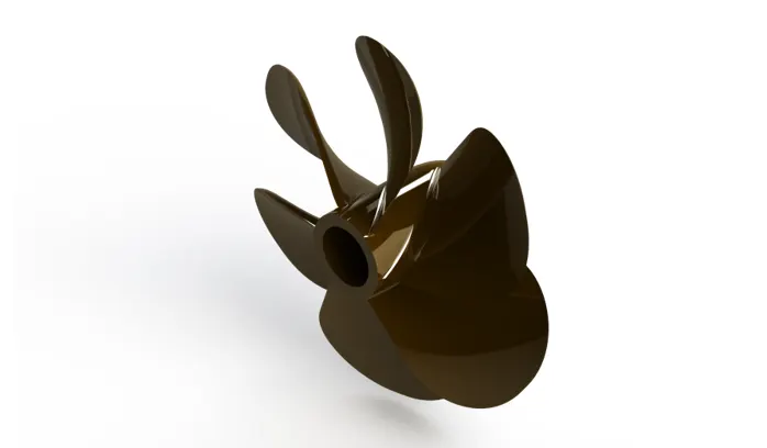
Commands used: Sketch, revolve-extrude, loft-extrude, cut-extrude, fillet, and circular pattern.
Sketch - When we open a new part document, first we create a sketch(2D/3D) to create the 3D model. The sketch is the basis for a 3D model. We can create a sketch on any of the default planes (Front Plane, Top Plane, and Right Plane), or a created plane. We can also create sketches on the face of the part.
Revolve-Extrude - The revolve feature enables to add materials to the 20 sketches by revolving about a centerline or an axis. This actually rotates the sketch about an axis.
Loft-Extrude - It helps to create a solid model between two profiles at a certain distance. It needs two or more
profiles to add materials to it.
Cut-Extrude - Unlike the extrude boss, the Extrude cut removes the material from 3D
model by using a closed sketch (circle or rectangle etc). We can do the
cut in one or two directions using the property menu.
Fillet - It creates round internal or external faces by using the edges of the solid model. You
can control the radius of the fillet from the property manager.
Circular pattern - The circular pattern used here is used to pattern a solid body or a feature about a circular edge or a point.
- Radar:
The Radar in the yacht is used to detect other ships and land obstacles, to provide bearing and distance for collision avoidance and navigation at sea. They are electronic navigation instruments that use a rotating antenna to sweep a narrow beam of microwaves around the water surface surrounding the ship to the horizon, detecting targets by microwaves reflected from them, generating a picture of the ship's surroundings on a display screen. Radar is a vital navigation component for safety at sea and near the shore.
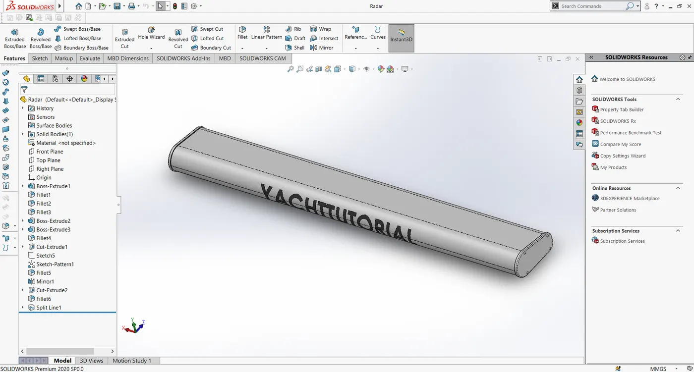
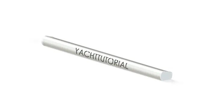
Commands used: Sketch, Boss-extrude, cut extrude, sketch pattern, fillet, mirror, split line.
Sketch pattern: This feature is used to create more instances of the feature body with reference to some sketch points.
Mirror : This feature is used to create a mirrored body or a feature. it needs a plane or a surface to be selected as the mirror plane.
Split line : This tool projects an entity (sketch, surface, solid, face, plane, or surface spline) to surfaces, or curved or planar faces. It divides a
selected face into multiple separate faces. You can split curves on multiple bodies with one command.
- Hull:
A hull is the watertight body of a ship or boat. The hull may open at the top, or it may be fully or partially covered with a deck. Atop the deck may be a deckhouse and other superstructures, such as a funnel, derrick, or mast. The line where the hull meets the water surface is called the waterline.
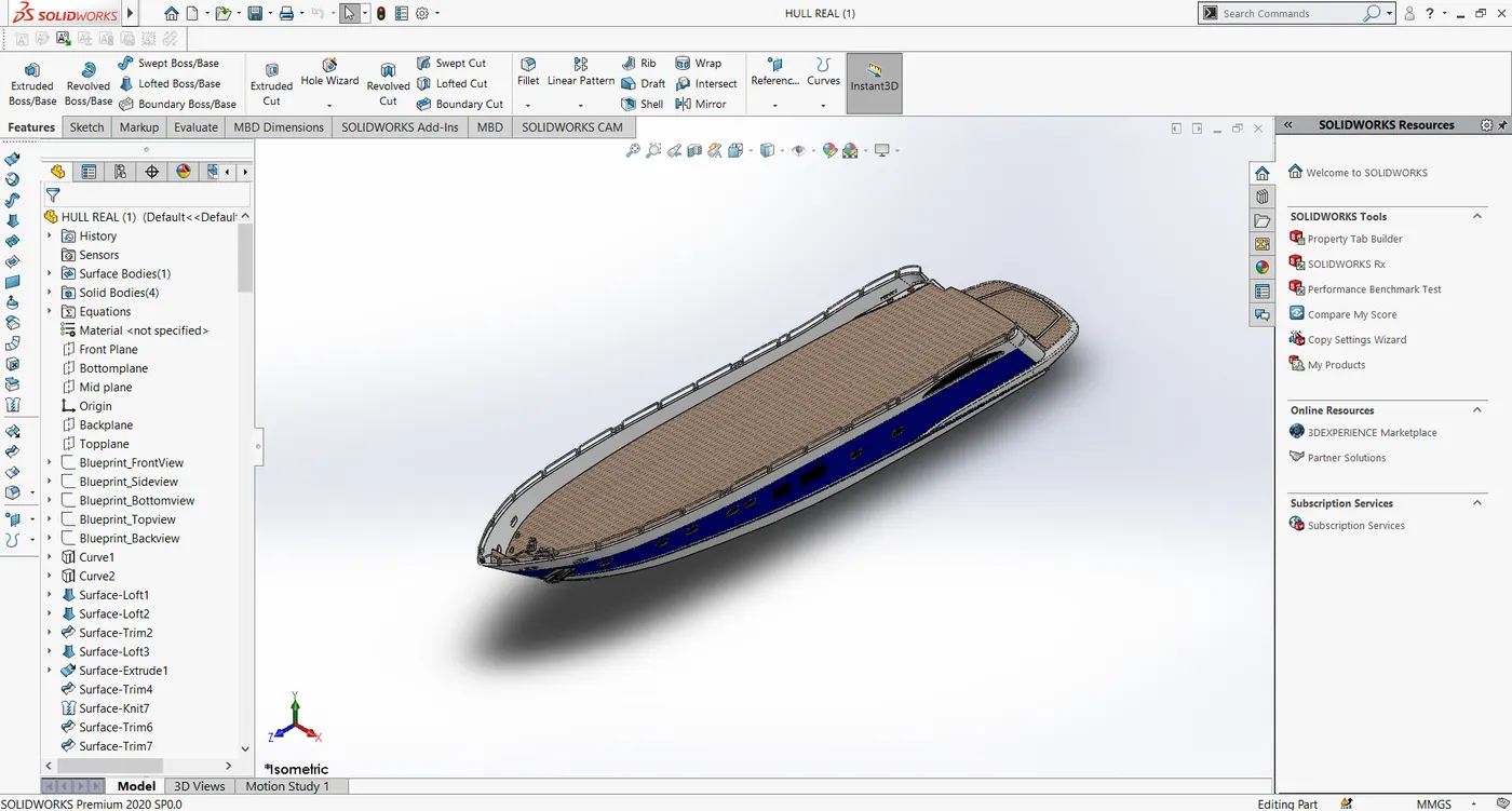
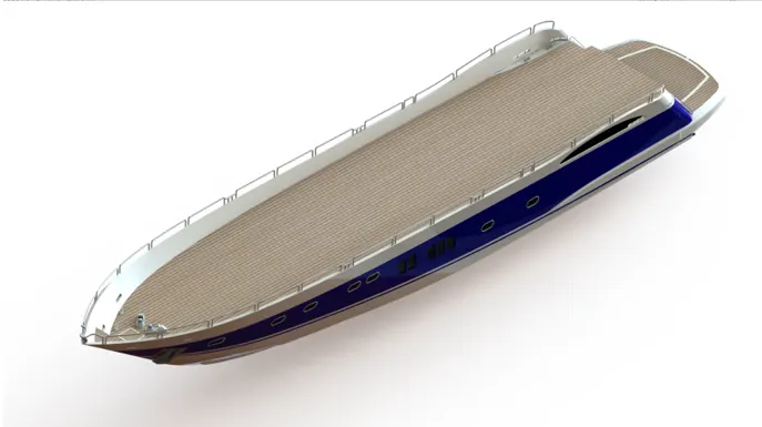
Commands used: Sketch, Projected Curves, Surface-loft, Surface-extrude, Surface-Trim, Surface fill, boundary surface, shell, dome, helix and spiral, fillet, combine, revolve-extrude, boss-Sweep, Surface extend, delete-face, fillet, and chamfer, Knit-surface.
Project curve A projected curve is a type of curves, it uses two sketches and the resultant is the intersection of imaginary surface intersection from the two sketches,
Loft-surface: It is created using multiple 3D curves by ensuring tangency between the selected curves
Fill surface: it constructs a surface patch with any number of sides within a boundary defined by the existing model.
Surface trim - To trim the surface by using a sketch.
Surface-extend extends the edge of the surface to a distance or based on the extension type.
Surface extrude: It is used to extrude a surface from the sketch.
Surface-fill: It is used to create a surface in by specifying the boundary extent.
Boundary-Surface: It is used to create a surface along with the selected boundary edges or sketches with guide curve specified.
Shell This tool hollows out a part leaves open the faces you select and creates thin-walled features on the remaining faces.
chamfer: it is used to create beveled features on selected edges, faces or a vertex,
Boss-Sweep using this feature we can create a shape by moving 20 sketch profiles along a 2D or 3D sketch path
Helix/Spiral: this command creates a helix/spiral base curve.
Dome: It is used to create a uniform circular projection on the surface.
Delete face : It is used to delete unnecessary faces.
combine: It combines two or more bodies.
Knit Surface: It is used to knit two or more surfaces into a single surface.
- Garage Door:
The garage door is a large door in a garage. It is large enough to accommodate automobiles. it is usually a single piece, but in some types, the garage door is made by using several joints to and it can be actuated either manually or automatically.
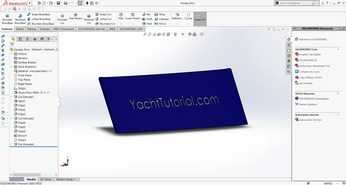
Commands used: Sketch, but extrude, fillet, shell, mirror.
- Superstructure:
A superstructure is an upward extension of an existing structure above a baseline. The superstructure consists of the parts of the ship or a boat, including sailboats, fishing boats, passenger ships, and submarines, that project above her main deck. This does not usually include its masts or any armament turrets.
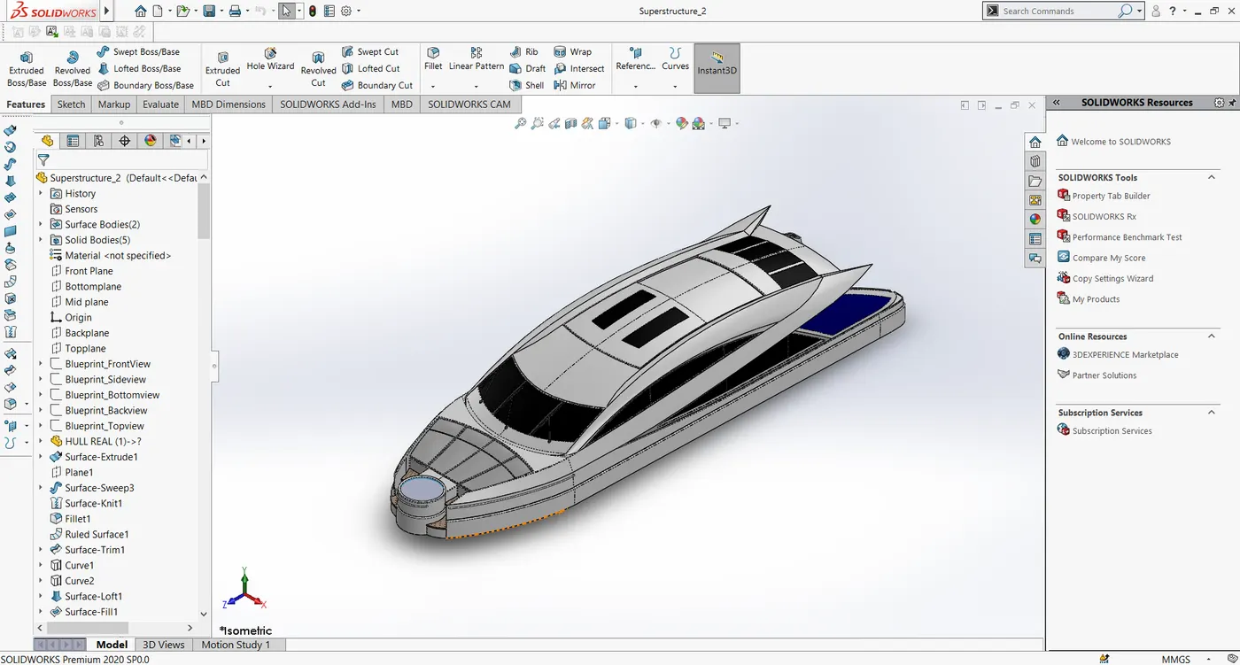
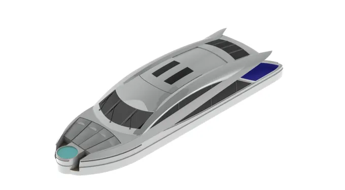
Commands used: Sketch, Projected Curves, Surface-loft, Surface-extrude, Surface-Trim, Surface fill, boundary surface, dome, fillet, combine, revolve-extrude, boss-Sweep, Surface extend, delete-face, fillet, chamfer, ruled surface, knit surface, surface-sweep, boss-sweep. cut-extrude, boss-extrude, Thicken Surface.
Ruled Surface: The ruled surface option is used to create a surface by specifying a reference plane for the sketch and the draft angle can also be specified.
Surface Sweep: It is used to create a surface of a sketch profile along with the guide curve.
Surface-thicken: It is used to increase the thickness of the surface, it actually converts a surface body into a solid body.
- Front Seat:
This seat goes in front of the superstructure. it is placed near the ship's front.
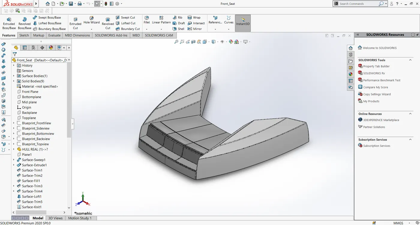
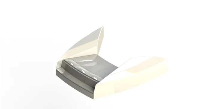
Commands used:
Sketch, Sweep surface, Surface trim, Surface Extrude, Surface knit, Surface loft, Revolve, Chamfer, Fillet, Mirror, cut extrude.
- Middle Seat:
The middle seat is placed at the end of the superstructure.
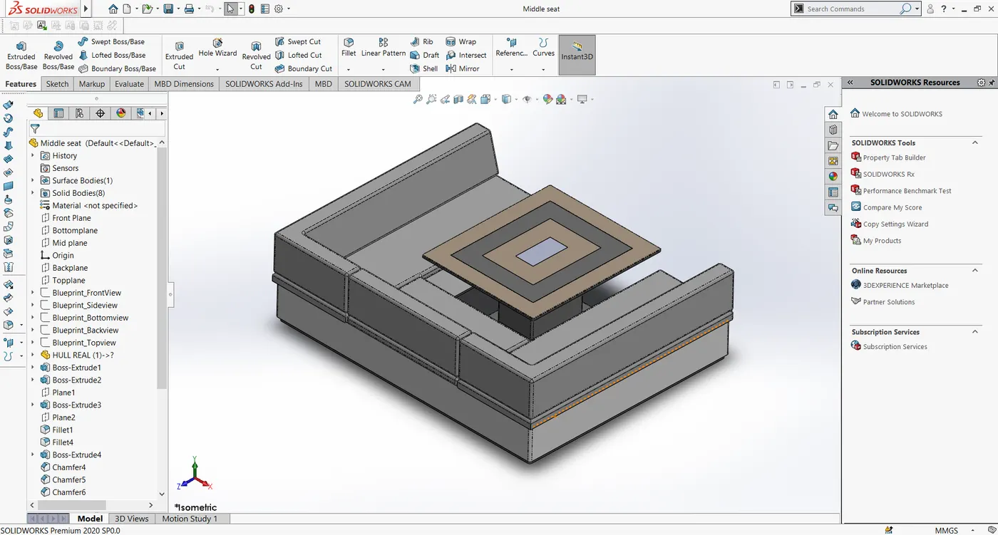
Commands Used: Boss-extrude, cut-extrude, fillet, chamfer, mirror.
- Rear Seat:
The rear seat is at the end of the surface deck of the hull.
It is positioned at a distance of 50 mm from the surface ed of the deck surface.
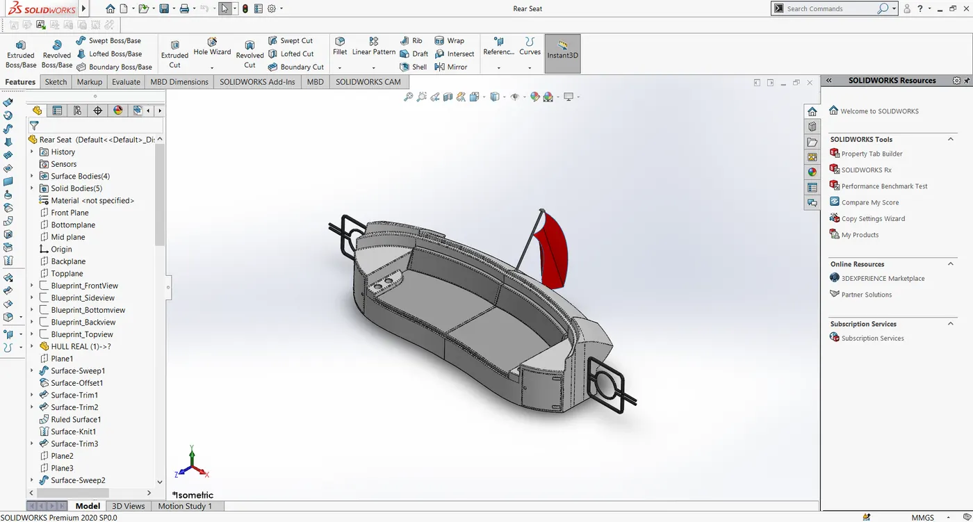
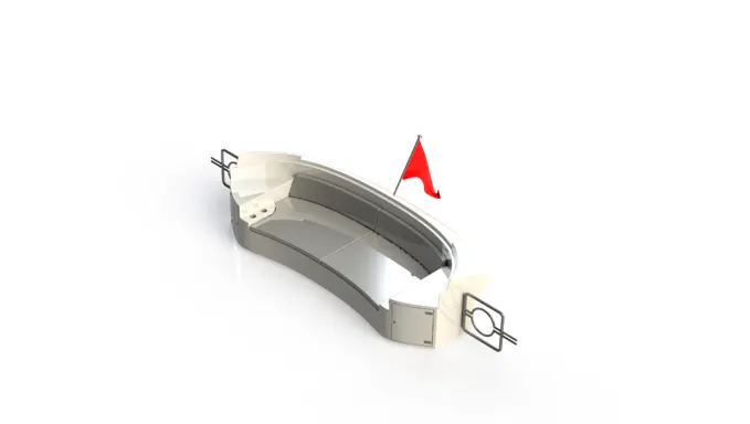
Commands Used: sketch, Surface-sweep, surface-loft, surface-extrude, surface-trim, offset- surface, boss-sweep, mirror, cut extrude, boss-extrude, mirror, fillet, chamfer, knit-surafce.
Offset Surface - It is used to offset the surface to a distance given by us.
- Radar Mast:
Radar mast is the mount for the radar.
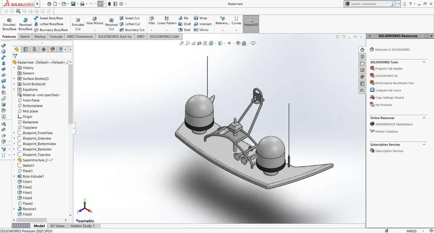
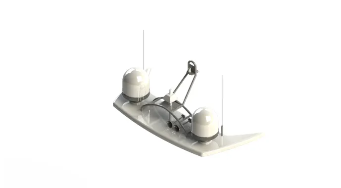
Commands Used: Sketch, boss-extrude, revolve, fillet, chamfer, boss-sweep, projected curves, etc..
Assembly of Yacht:
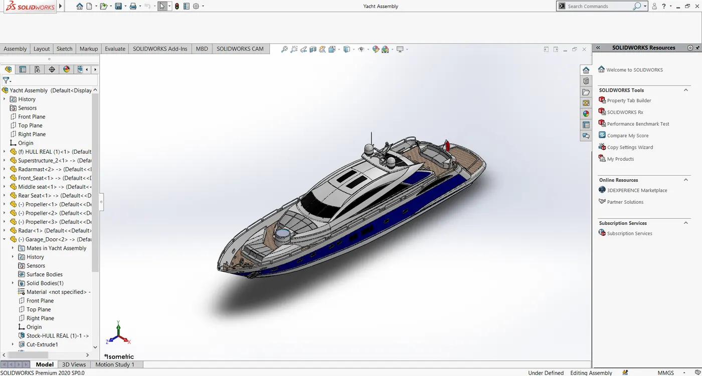
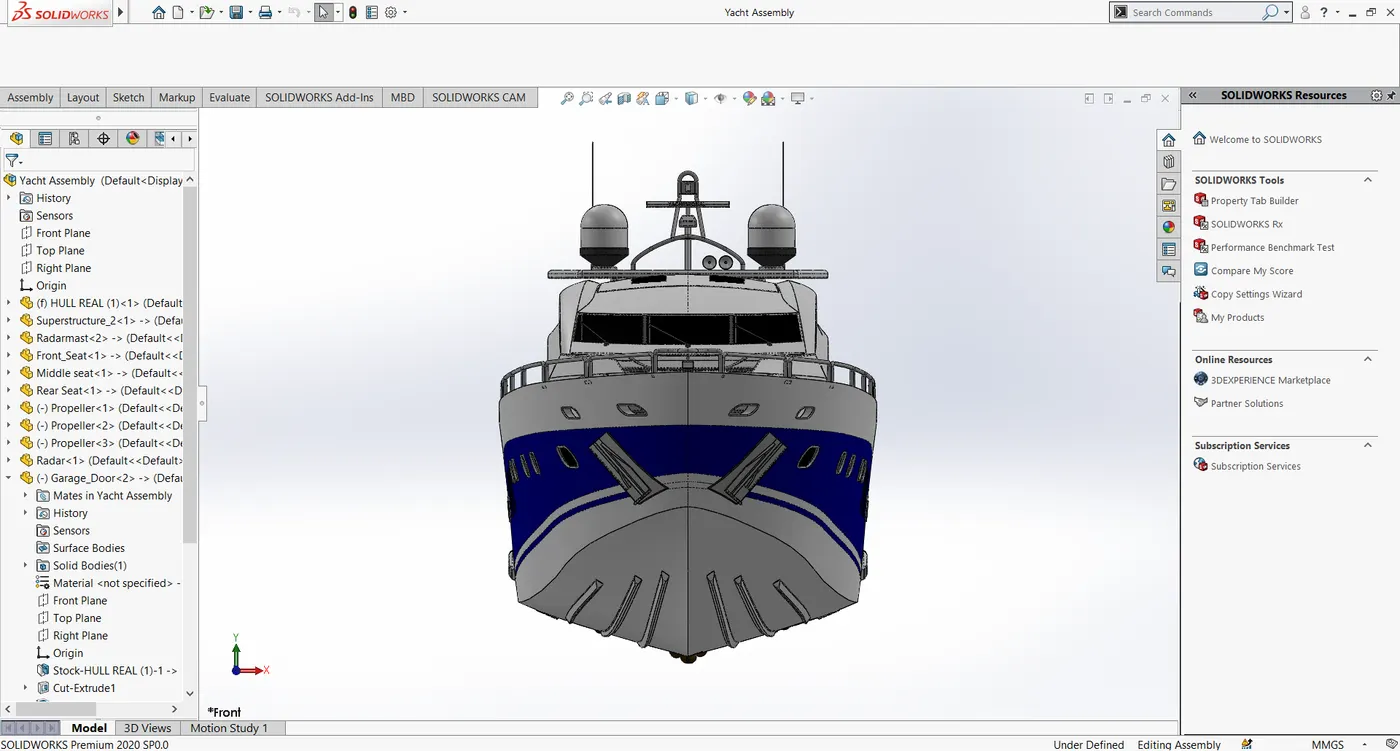
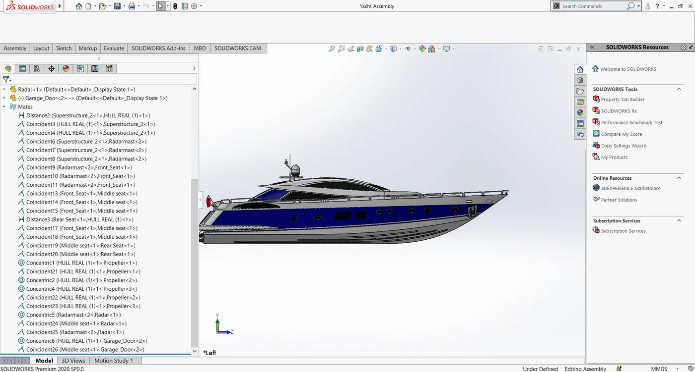
The yacht assembly is easy. Since the superstructure, Radar mast, and the seats are created with the deck surface as the reference they have mated automatically with a coincident relation. But the rear seat is mated manually with a Distance mate of 50 mm. from the point in the garage door, it also has a Coincident relation with the deck surface.
The propellers are mated with the Concentric relation.
The radar is mated to the Radar mast with a Concentric relation.
The Garage door is mated to the hull by using Concentric Relation with the projections on both sides.
The chopper model is Inserted and the midplane of the hull and chopper are mated with Coincident relation.
The Top plane of the chopper is made Coincident with the garage surface.
The assembly file will have the extension .sldasm
Rendering:
Photoview 360
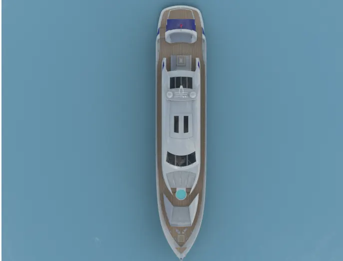
in Photoview 360 add-in the environment for the yacht render is selected and the various properties such as the gamma value are manipulated accordingly to get a good render. A camera is set up to get the renders and the lights are added and adjusted to get a fine render.
SOLIDWORKS VISUALIZE:
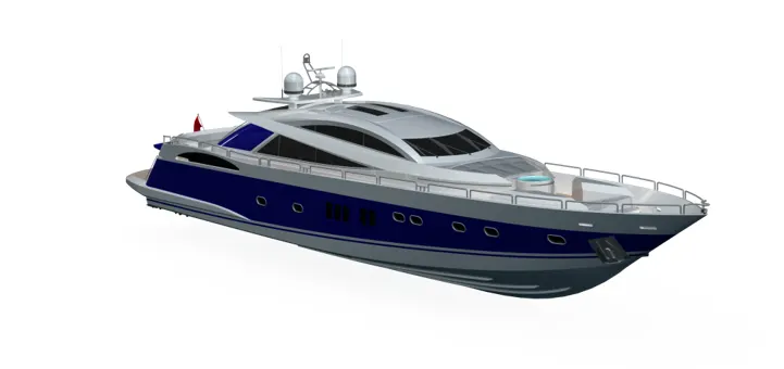
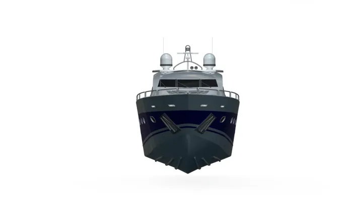
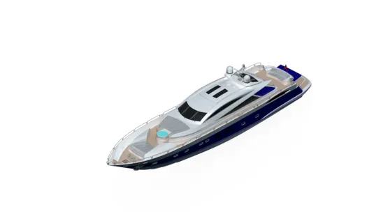
The renders created by photoview 360 are good but they don't look as realistic as possible. The Solidworks Visualize is a standalone rendering software that is capable of many features that lack in other CAD render software. The suitable HDR environment is chosen and the desired position is fixed to create the render. The appearances can also be changed in the software itself and the render settings can be manipulated to achieve the best photo-realistic appearances and also to decide the quality of the render.
CONCLUSION:
Thus the sunseeker predator yacht is modeled using the various surface and part modeling features of the SolidWorks. And a photorealistic rendering of the same is done using the photo view 360 and Solidworks Visualize software.