Photo Realistic Rendering
https://drive.google.com/file/d/1KgCRxqafOFeswANMuqwKXPWD_74ps7N7/view?usp=drive_link
MODELING OF AMERICAN CHOPPER IN SOLIDWORKS
- Objectives-
- The main objectives of this project are:
- To create individual parts of chopper using solidworks
- To assemble all the individual parts into chopper
- to know the application of decals,lights and camera etc
- To create photorealistic model and render it using photoview 360 and solidwork visualize
- Introduction-
- Solidworks is one of the prominent modelling software avaliable today this software is mainly used to model 3D parts using 2D sketch.It also has the option to specify the material and look of the model which we created.It has other ADD-in features like photoview360 which helps in rendering of the final model to make it look photo realistic. In this project we learnt about detailed design of Americal chopper parts and assemblig them and rendering the final after assembly.
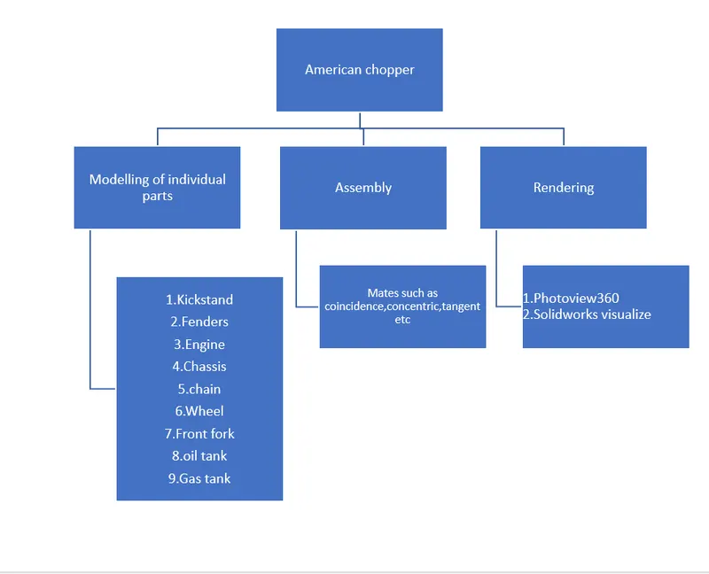
- SOLIDWORKS FEATURES USED
- Line: This feature allows us to create a straight line. The line can be a solid line or a construction line.
- Circle: This feature allows us to create circles.
- Rectangle: This feature allows us to create squares or rectangles.
- Spline: This allows us to make curved line Curve Projection: this is used for the projection of the curves made in different planes to create an intersected curve.
- Arc: This allows us to create arc.
- Projected Curve: It is a powerful tool which can project two different 2D splines from two different planes into a single spline or a curve in 3D which can meet our need. It is the most often used feature before creating any surface.
- Split: This feature is used to split to bodies using a sketch.
- Trim: This is used to trim sketches.
- Extend: This feature allows us to extend the sketches
- Extrude Bose: This feature allows us to create solid bodies.
- Extrude cut: This feature allows us to create cuts or holes of any shape in the solid body.
- Swept Bose: This feature allows us to make a solid body along a curve path or create a curved solid body.
- Mirror: This feature allows us to create exact copy of the solid body using a reference plane or face.
- Revolve: This allows us to create revolve solid body around an axis.
- Linear Pattern: This allows us to create a pattern in a straight line.
- Circular Pattern: This allows us to create a pattern in a circle.
- Fillet: This is used to create circular edges.
- Chamfer: This is used to create inclined edges.
- Plane: This feature is used to create new planes.
- Loft: This feature allows us to make solid bodies with uneven geometry.
- Dome: This feature is used to make a dome shaped solid over a flat solid body. O Shell: This is used to make a hollow solid body.
- Mirror Entities: This is used to create a mirror of sketch.
- Split Entities: This is used to split a line into two or more parts.
- Split line: The Split line is used to divide parts into multiple bodies. You can use the Split line feature to save the new bodies when you split the part or use the Save Bodies to save them after the split is complete.
- Convert Entities - Converts selected model edges or Sketch entities into Sketch segments.
- Loft: this is creating a feature by making transitions between profiles. A loft can be a base, boss, cut, or surface. We can create a lot using two or more profiles. For a solid loft, the first and last profiles must be model faces or faces created by split lines, planar profiles, or surfaces.
- Fillet: this is creating a rounded internal or external face on the part. We can fillet all edges of a face, selected sets of faces, selected edges, or edge loops.
- Helix: this is creating a helix or spiral curve in a part. The curve can be used as a path or guide curve for a swept feature, or a guide curve for a lofted feature.
- Loft Surface: Loft Surfaces are surfaces generated by multiple 3D Curves or existing edges creating a smooth tangency between the selected curves.
- Surface trim: it is used to cut away material from a surface and provides two modes: Standard and Mutual.
- Extend Surface: it is used to extend the surface which is already created. There are different options available on the extended surface. We can extend the surface as same surface, or we can extend the surface tangent to the surface.
- Surface knit: it is used to knit the two free edges/open edges of the surfaces together. Also, it reduces the gap between the two edges of the surface.
- Sweep Surfaces: this is surfaces that are generated from a section curve positioned along a path.
- Filled Surface: this Surface feature constructs a surface patch with any number of sides, within a boundary defined by existing model edges, sketches, or curves, including composite curves.
- Ruled surfaces: it is used to obtain the extruded surface perpendicular to the plane and can be titled in certain angle
- Rollback: Rollback is yet another powerful tool that allows going back to any phase of design in case if we need to edit or add some features later. We can use roll-up bar while removing errors too. This reduces the rebuild time and avoids further errors in the children features.
- Combine Tool:
- Combining Bodies - Add: in a multibody part, you can combine multiple bodies to create a single body.
- Combining Bodies - Subtract: In a multibody part, you can subtract one or more bodies from another body.
- Combining Bodies - Common: In a multibody part, you can create a body defined by the intersection of multiple bodies.
- Combine Property Manager: In the Combine Property Manager, you specify which bodies in a multibody part to add, subtract, or overlap.
- Delete/Keep Body: You can select bodies to keep or delete using the Delete/Keep Body feature. This is useful in working with multibody ports with multiple configurations.
- MODELLING COMPONENTS
- In this project most of the parts are designed to be multiple body parts to make the workflow faster and simple. It makes a lot easier in the assembly phase and decreases rebuilding time. As it is a cosmetic model of the bike it is all solid modelling. The following are the individual parts designed in SOUDWORKS and rendered in SOLIDWORKS Photoview 360.
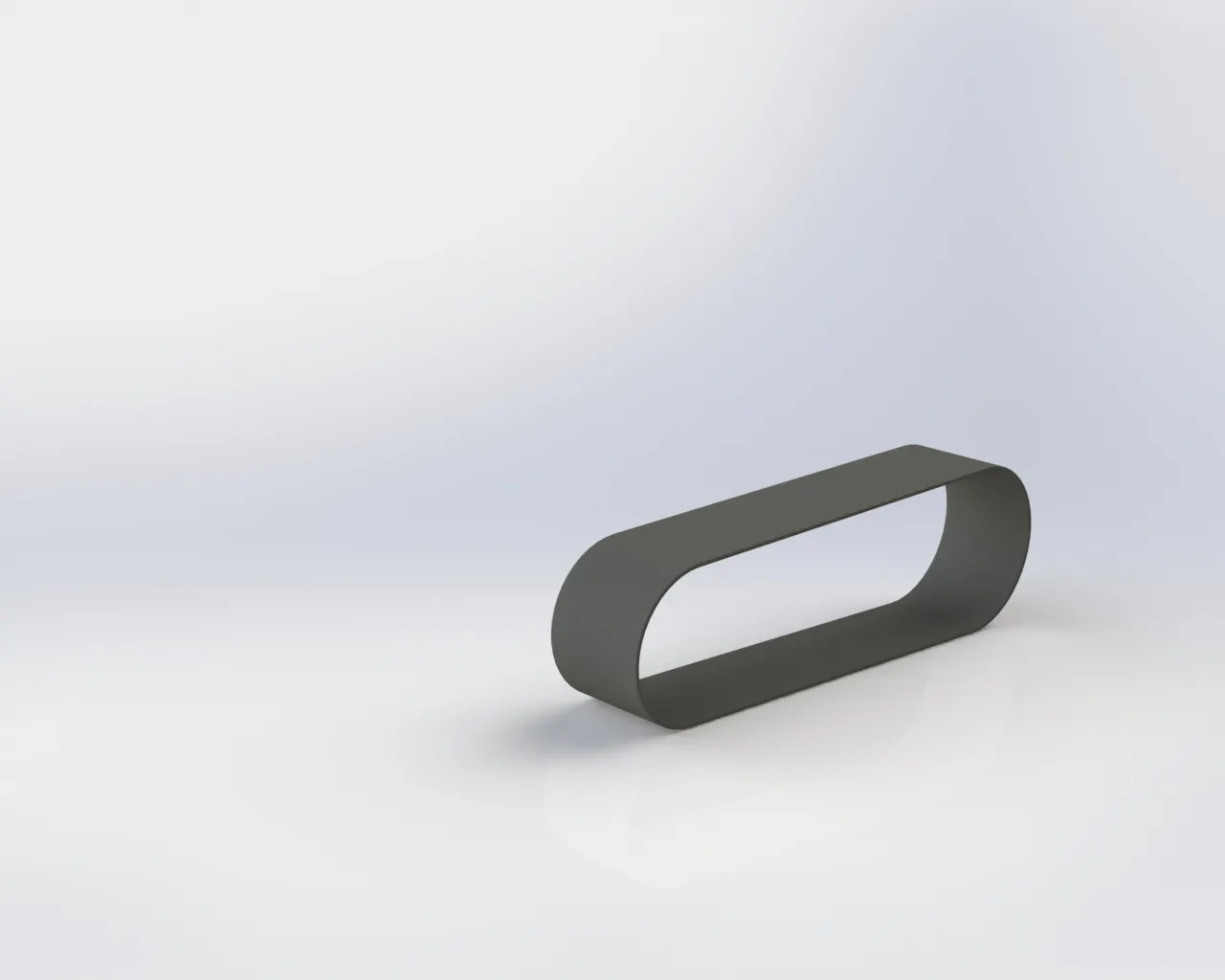
- 1. Transmission Belt
- The belts are used to transmit power from one shaft to another by means of pulleys which rotate at the same speed or at different speeds. In this chopper, transmission belt is used for transmitting power from crankshaft to sprocket. From sprocket power transmitted to wheels using chain.
- Feature Tool: Extruded boss/base and fillet
- Sketch Tool: Sketch Geometry line and offset entities
- Appearance: Matte Rubber
- Render Image: Photo view 360
- Procedure for modelling transmission belt in brief.
- The first step for modelling the transmission belt is to draw the sketch of the cross - sectional view of the belt.
- Extrude the sketch drawn in the previous step up to required dimensions.
- Provide fillet to the sharp edges.
- Apply material properties to the belt as per requirement.
- 2. Kick Stand
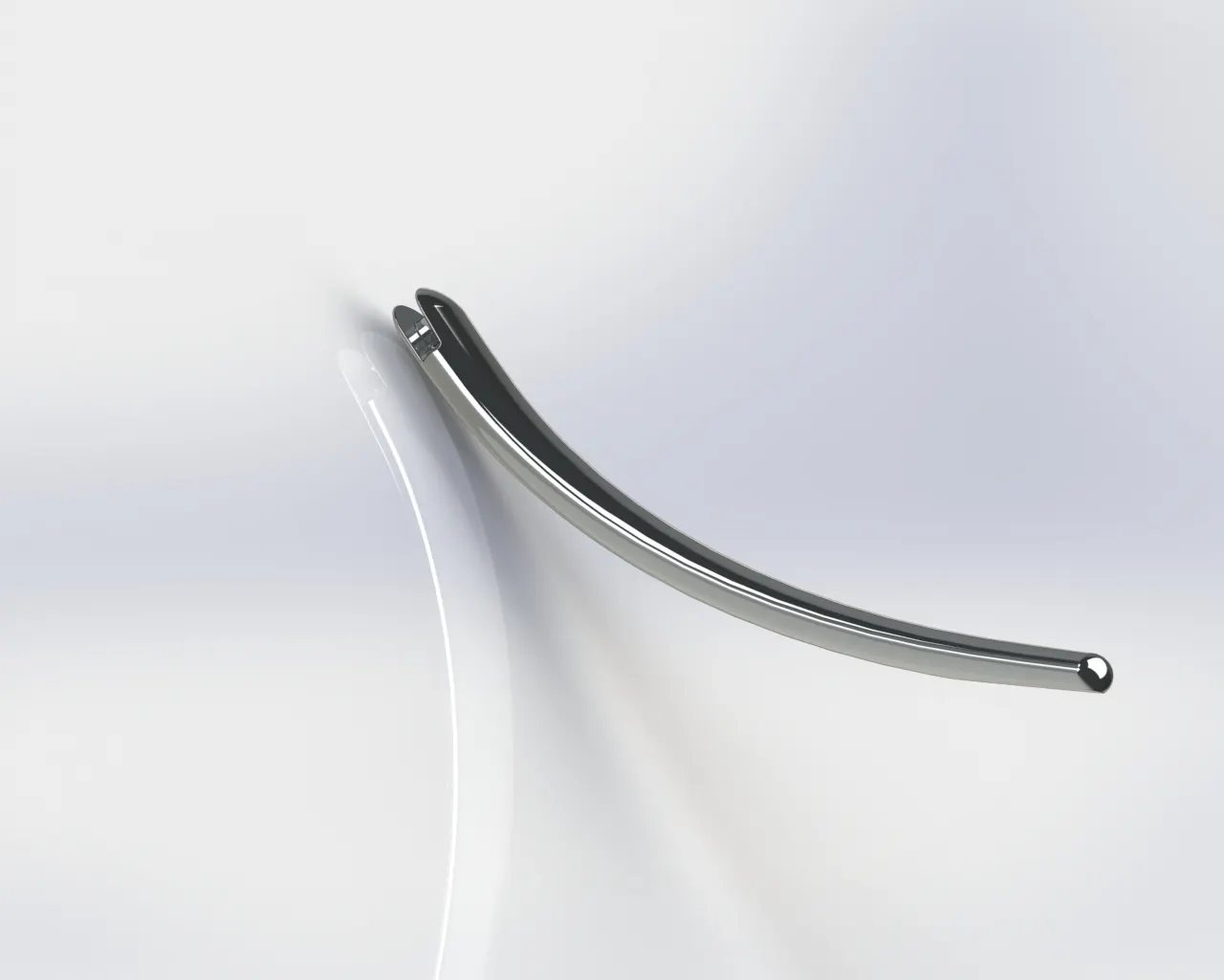
- Kickstand or commonly called as side stand used to balance the motorcycle when it is parked.
- The kickstand is basically a rod made of steel / iron and it is placed on the chassis. It is usually in a curved shape.
- It can be rotated about 90 °
- Feature Tool: Pierce, Spline, Lofted Boss / Base, Extruded cut, Extruded Boss / Base.
- Sketch Tool: Ellipse, Spline
- Appearance: Chrome Steel
- Render Image: Photo View 360
- Procedure for modelling kickstand in brief.
- Open a new part design and draw an ellipse in the front plane with appropriate dimension.
- In mid - plane, draw a spline path for defining the shape of the kickstand.
- In a plane perpendicular to the curve created in the previous step, draw another ellipse with appropriate dimensions.
- Use loft boss / base option and loft between 2 ellipses through guideline (spline).
- Create dome on both of the elliptical surface.
- Create slot on one side of the kickstand for inserting it on the chassis.
- In the smaller ellipse side, remove a portion of kicker stand to make a flat surface.
- Provide fillet to sharp edges.
- Change the appearance of the kickstand by applying a suitable material.
-
3. PEDAL
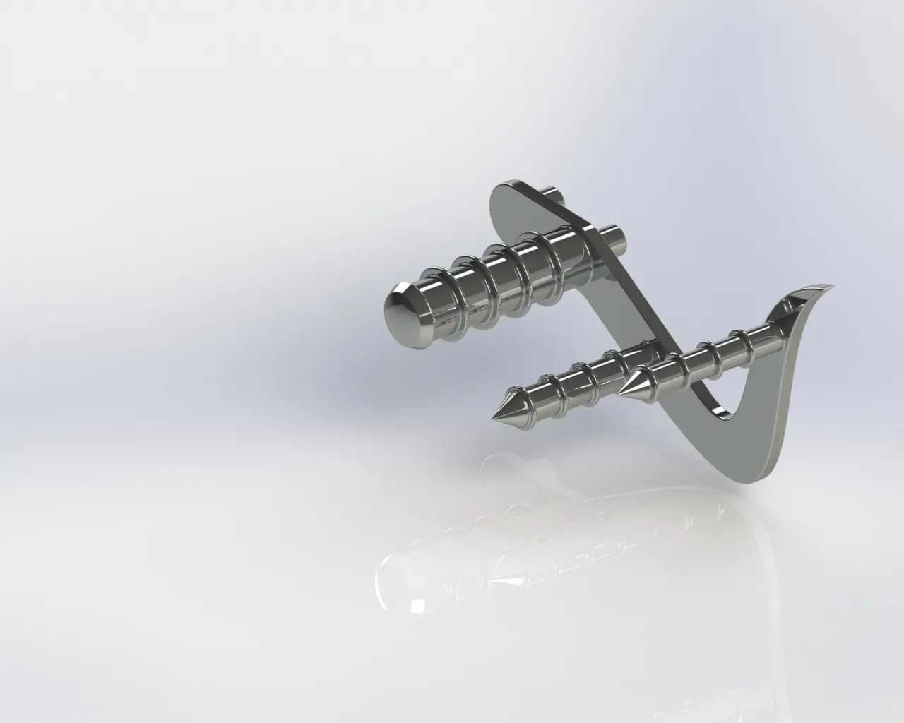
- The pedal is a type of lever used for applying torque.
- This torque is used for brake application, gear changing, etc. in the case of motorcycles
- In this chopper two pedals are used; one is for application of brake and another used for gear shifting
- Pedals are usually made up of alloy metals.
- Feature Tool: Revolve boss / base, Extrude boss / base, dome, linear pattern, chamfer and fillet
- Sketch Tool: Sketch Geometry like line, spline and circle
- Appearance: Chrome steel
- Render Image: Photo View 360
Procedure for modelling pedal in brief.
- The first step for modelling the pedal is to draw the sketch of the base of the pedal and extrude it up to required height.
- Draw the sketch of the base of pedal rods on the surface of the base and extrude it.
- Provide fillet to all the sharp edges.
- Create projected rings on the rod of the pedal for increasing grip and to facilitate insertion of the rubber grip.
- Apply suitable material to the pedal
-
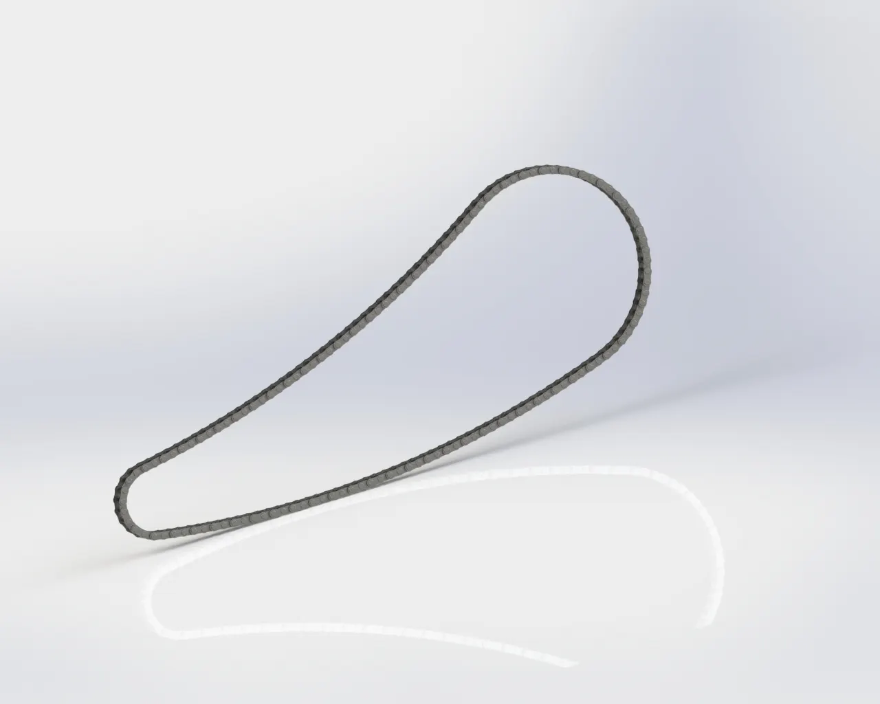
4 chain
- A chain drive is one of the ways to transmit power from one place to another. It is commonly used in bicycles and motorcycles for power transmission.
- The chains are made up of a number of rigid links which are hinged together by pin joints in order to provide the necessary flexibility for wrapping around the driving and driven wheels.
- These wheels have projecting teeth of special profile and fit into the corresponding recesses in the links of the chain.
- The toothed wheels are known as sprocket wheels or simply sprockets. The sprockets and the chain are thus constrained to move together without slipping and ensure perfect velocity ratio.
- The chains are mostly used to transmit motion and power from one shaft to another when the centre distance between their shafts is short such as in bicycles, motorcycles, agricultural machinery, conveyors, rolling mills, road rollers etc.
- Feature Tool: Extrude boss / base, Curve driven Pattern, mirror, Block and fillet
- Sketch Tool: Sketch Geometry like line, straight slots, 3 - point arc and circle
- Appearance: Chrome steel for plates and brushed metal for pin
- Render Image: Photo View 360
Procedure for modelling chain in brief:
- As the chain is made up of combining many links, the first step in modelling chains is to create the single link's sketch as per given dimension and save it as a block.
- Create the path in which these links have to be assembled for creating the whole chain.
- Place one link at any point on the path created in the previous step and create a curve driven pattern of the link along the same path.
- Connect the last two links by creating an additional link
- Apply suitable material for the chain.
-
5. FRONT FENDER and REAR FENDER
- Fender also called as a mudguard, is mainly used to prevent sand, mud, liquids etc. which is thrown into the air by the rotating wheel.
- It is usually made up of fibres, steel and similar materials.
- It is kept just above the wheels and fixed on the chassis / front fork.
- In this model of American chopper, two types of fenders are used- Rear fender and Front fender
- The rear fender is used above the rear wheel and fixed on the chassis.
- Rear fenders are usually bigger in size compared to front fender since rear wheels are usually bigger in size for the case of motorcycles.
- The front fender is used above the front wheel and is fixed on the front fork.
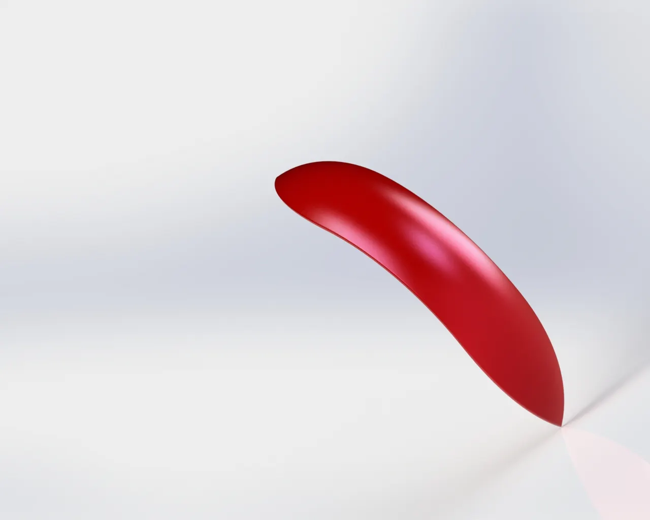
Procedure for modelling Front fender in brief
- The first step for modelling the front fender is to draw the sketch of the cross - sectional view of the fender and revolve it to form an arc of required dimension.
- Remove some portion on both sides of the fender for better appearance of the fender as shown in the figure given below.
- Extra portions are removed by drawing a spline on the appropriate plane and splitting the fender into different portions.
- Now provide fillet to all the sharp edges.
- Apply appropriate colour for the fender.
- Feature Tool: Revolve boss / base, spline and filet
- Sketch Tool: Sketch Geometry like line, spline and 3 - point ore Extended entities and from Ends.
- Appearance: Rose Gold
- Render Image: Photo View 360
-
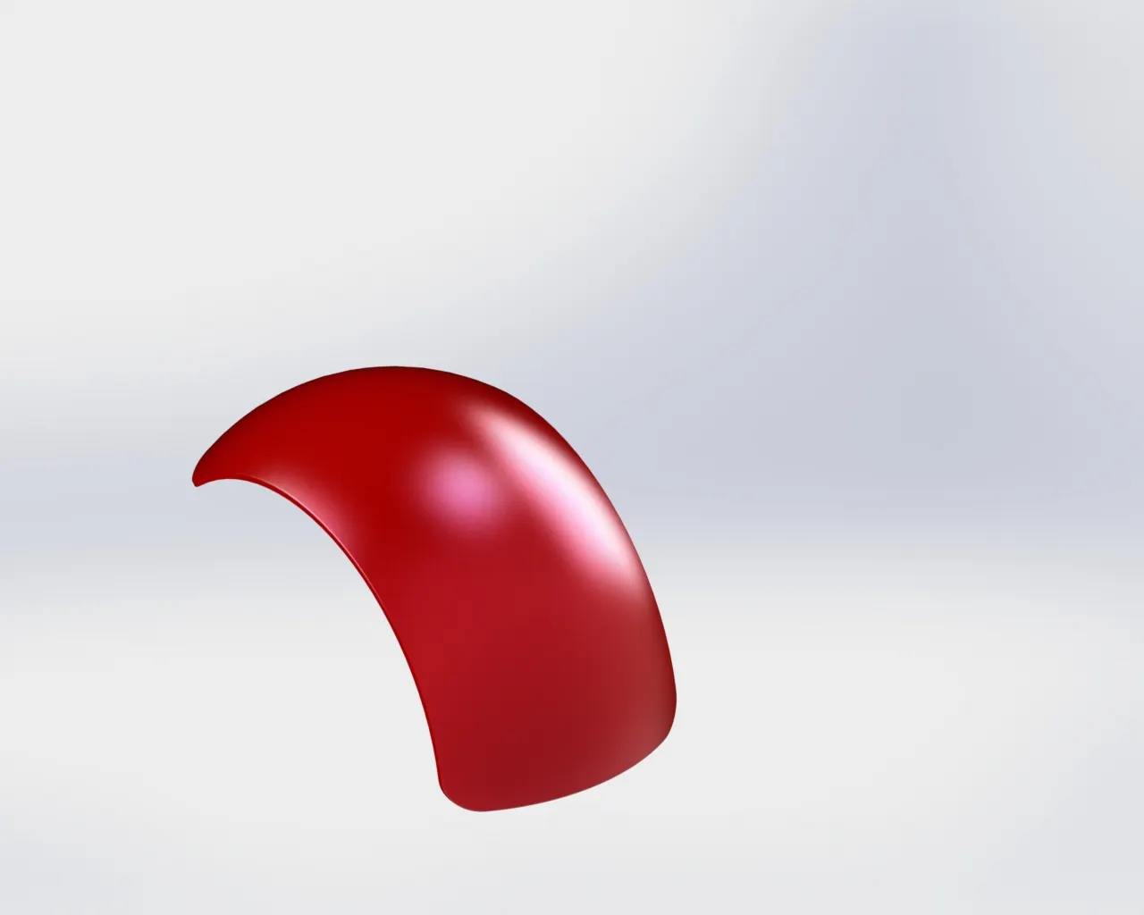
Procedure for modelling Rear fender in brief:
- The first step for modelling the rear fader is to draw the cross - sectional sketch of the fender and revolve it to form an arc of required dimension.
- Remove some portion on both sides of the fender for better appearance of the fender as shown in the figure given below.
- Extra portions are removed by drawing a spline on the appropriate plane and splitting the fender into different portions.
- Provide fillet to all the sharp edges.
- Apply the appropriate colour for the fender.
- Feature Tool: Revolve boss / base, spline, shell and fillet.
- Appearance:Rose Gold.
- Sketch Tool: Sketch Geometry like line, spline and 3 - point arc Extended entities, Trim Entities and offset Entities.
- Render Image: Photo View 360
-
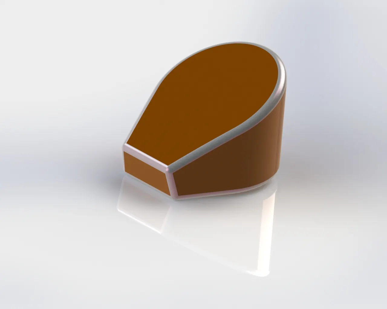
6. OIL TANK
- Oil tanks are basically storage tank used for storing oil which is used in the chopper. It is placed in between the engine and fuel tank. Capacity and shape of the tank may be different for different types of vehicles. Oil tanks are usually made up of steel.
- Feature Tool: Extrude boss / base, combine, shell and fillet.
- Sketch Tool: Sketch Geometry like line, Spline and circle.
- Appearance: Rose Gold
- Render Image: Photo View 360
Procedure for modelling oil tank in brief.
- The first step for modelling the oil tank is to draw the sketch of the top view of the tank.
- Extrude the sketch up to the required length.
- Draw the sketch of the front view of the tank and extrude it up to the required length.
- Combine both the solid by keeping a common portion between them.
- Apply fillet to all the sharp edges.
- Apply a suitable colour and material to the oil tank.
-
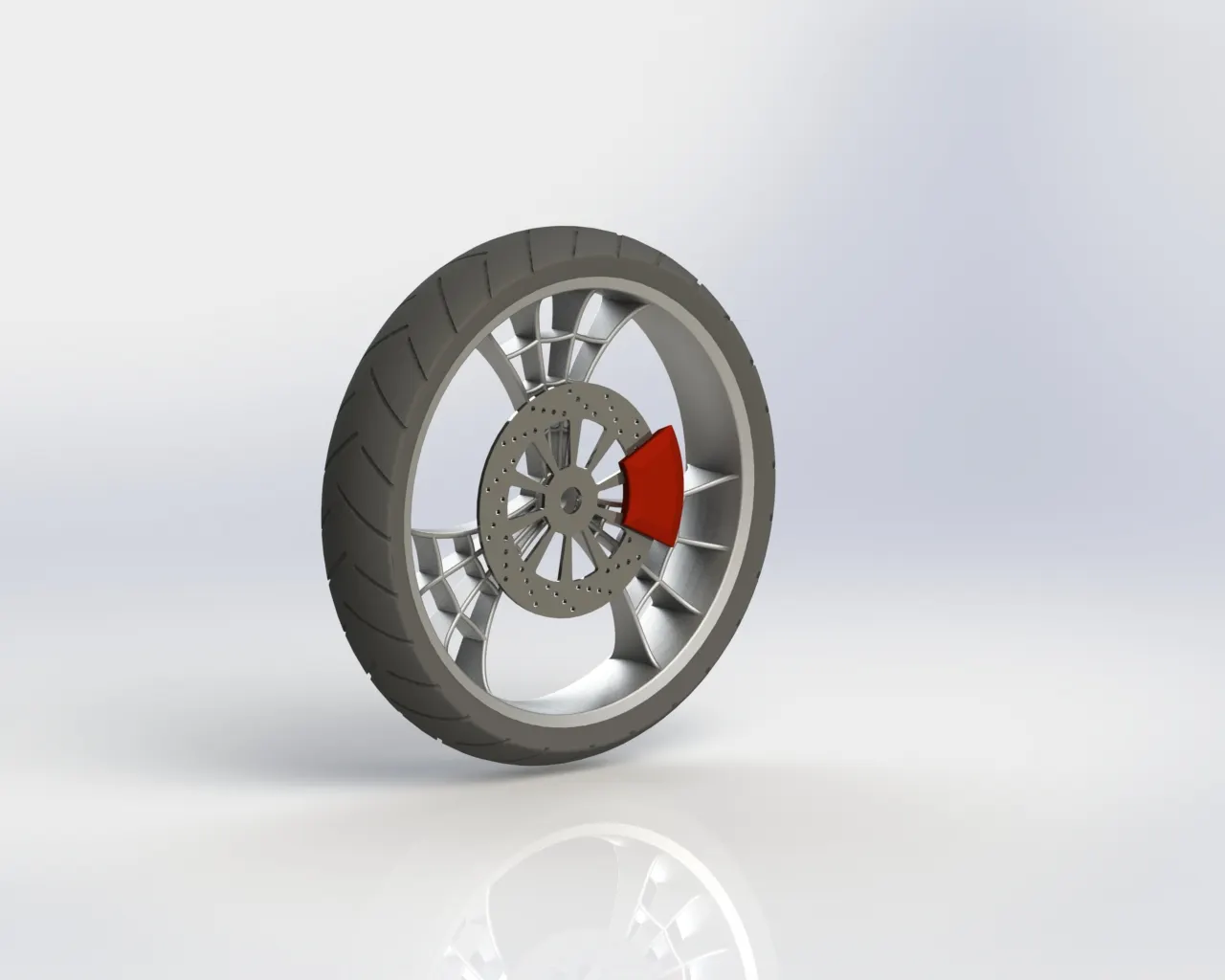
7. FRONT WHEEL
- Front - wheel consists of four parts - Rim, calliper, rotor and tyre
Rim:
- Rims are usually available in two forms- Spokes type and alloy type.
- Spokes type rims consist of a hub and round traction surface connected with many spokes. Alloy wheels are a single piece made by forging.
- Alloy wheels are made of an alloy of light metals, namely aluminium, nickel, magnesium, or a combination of these metals. Alloy wheels are lighter in weight.
- In this chopper, alloy wheels are used as rim and web comp structure is used for designing it.
Calliper:
- Calliper is the part which contains the brake system used in a chopper.
- Disk brakes are used in this chopper.
- Calliper is placed on the rotor and is connected to the brake levers using cables.
- When the brake is applied, the disc pads inside the calliper presses the rotor and reduce its speed
Rotor:
- Rotor (commonly called as a disc) is a metallic circular plate placed on the rim.
- The rotor consists of holes which help to transfer the heat produced due to friction while braking
Tyre:
- A tyre is a ring - shaped component that surrounds a wheel's rim. It transfers a vehicle's load from the axle through the wheel to the ground. It provides traction on the surface travelled over
- Materials used for manufacturing are synthetic rubber, natural rubber, fabric and wire, along with carbon black and other chemical compounds.
- Tyre used in front - wheel is usually smaller in size compared to the rear wheel.
- Tyre has to be changed at a regular interval based on the wear occurred.
- Feature Tool: Revolve boss / base, extrude boss / base, Revolve cut, circular pattern, mirror, chamfer and fillet.
- Sketch Tool: Sketch Geometry like line , spline, circle, 3 - point arc, rectangle, trim entities, extended entities, convert entities and offset entities.
- Appearance: Chrome steel for Rim, Brusher metal for Rotor, Rose Gold for Calliper and Matte Rubber Tire.
- Render Image : Photo View 360
Procedure for modelling front wheel in brief.
- Draw the cross - sectional view of the rim and revolve the sketch up to 360 °.
- Draw the sketch of the block where spokes have to be placed and extrude it.
- Draw a sketch of the web - shaped spokes in the block created in the last step and cut the unwanted portions.
- Now in the same plane draw ribs connecting all the spokes and extrude it.
- In mid - plane draw the curvature to remove excessive materials using revolve cut, from the rim created in the last step.
- In right plane draw the sketch required for creating disk pad (rotor) and extrude it.
- In the surface of the disk pad created in the last step and draw circular holes and cut it through the disc pad.
- Remove some material from the disc pad by drawing a hole using lines and arcs.
- Create an axle hole of appropriate diameter through rim and disc pad.
- Provide fillet to the required edges.
- In the front face of the disc draw the sketch of the calliper and extrude it.
- Provide chamfer to both sides of the calliper and fillet the sharper edges as per required dimension.
- In the front plane draw the sketch of the side view of the wheel and revolve it for getting the full model of the tyre.
- Now create the sketch on the front plane for thread cutting on the surface of the tyre.
- Using extrude cut option, create the thread cut on the surface of the tyre and copy that throughout the tyre surface using a circular pattern option.
- Now change the appearance of all the parts as per requirement and save the file.
-
8. REAR WHEEL
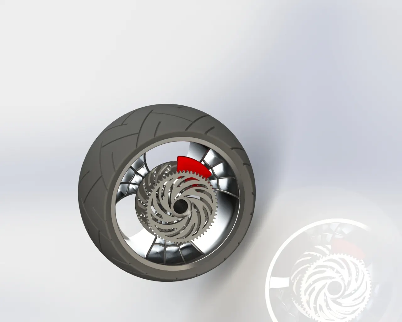
- Rear wheel consists of five parts - Rim, calliper, rotor, tire and a sprocket
- The rim, calliper, rotor and tire are already described above.
Sprocket
- A sprocket is a profiled wheel with teeth that mesh with a chain, track or other perforated or indented material
- Sprockets are used in bicycles, motorcycles, cars, tracked vehicles etc.
- Cast iron is commonly used for making sprockets. Sprockets are fixed on the rear wheel using bolts and nuts.
- Feature Tool: Revolve boss / base, extrude boss / base, Revolve cut, circular pattern, mirror, chamfer and fillet.
- Sketch Tool: Sketch Geometry like line, spline, circle, 3 - point arc, rectangle, trim entities, extended entities, convert entities and offset entities.
- Appearance: Chrome steel for Rim, Brusher metal for Rotor Brusher metal for Sprocket, Rose Gold for Calliper Matte Rubber for Tire.
- Render Image: Photo View 360
Procedure for modelling rear wheel in brief.
- Draw the cross - sectional view of the rim and revolve the sketch up to 360 °.
- In the front - plane draw the sketch of the block where spokes have to be placed and extrude it.
- Draw the sketch of spokes in the block created in the last step and cut the unwanted portions.
- In the same plane draw ribs connecting all the spokes and extrude it.
- In mid - plane draw the curvature to remove excessive materials using revolve cut, from the rim created in the last step.
- Create a circle in the right plane and cut it through the part for placing axle.
- Create a sketch on front - plane for making axle and revolve it.
- In right plane draw the sketch required for creating disk pad (rotor) and extrude it.
- In the surface of the disk pad created in the last step and draw circular holes and cut it through the disc pad.
- Remove some material from the disc pad by drawing a hole using lines and arcs
- Provide fillet to the required edges.
- In the Front face of the disc, draw the sketch of the calliper and extrude it.
- Provide chamfer to both sides of the calliper and fillet the sharper edges as per required dimension.
- On the outside face of the axle , draw a sketch for creating sprocket and extrude it.
- On the outside face of the sprocket draw the sketch of the teeth and cut it from the sprocket and then make a circular patter throughout the sprocket.
- Remove some material from the sprocket using a sketch on the outer surface of the sprocket.
- In the front plane draw the sketch of the side view of the wheel and revolve it so as to get the full model of the tyre.
- Create the sketch on the front plane for modelling thread cutting on the surface of the tyre.
- Using extrude cut option create the thread cut on the surface of the tyre and copy that throughout the tyre surface using circular pattern option
- Change the appearance of all the parts by adding appropriate material and save the file.
-
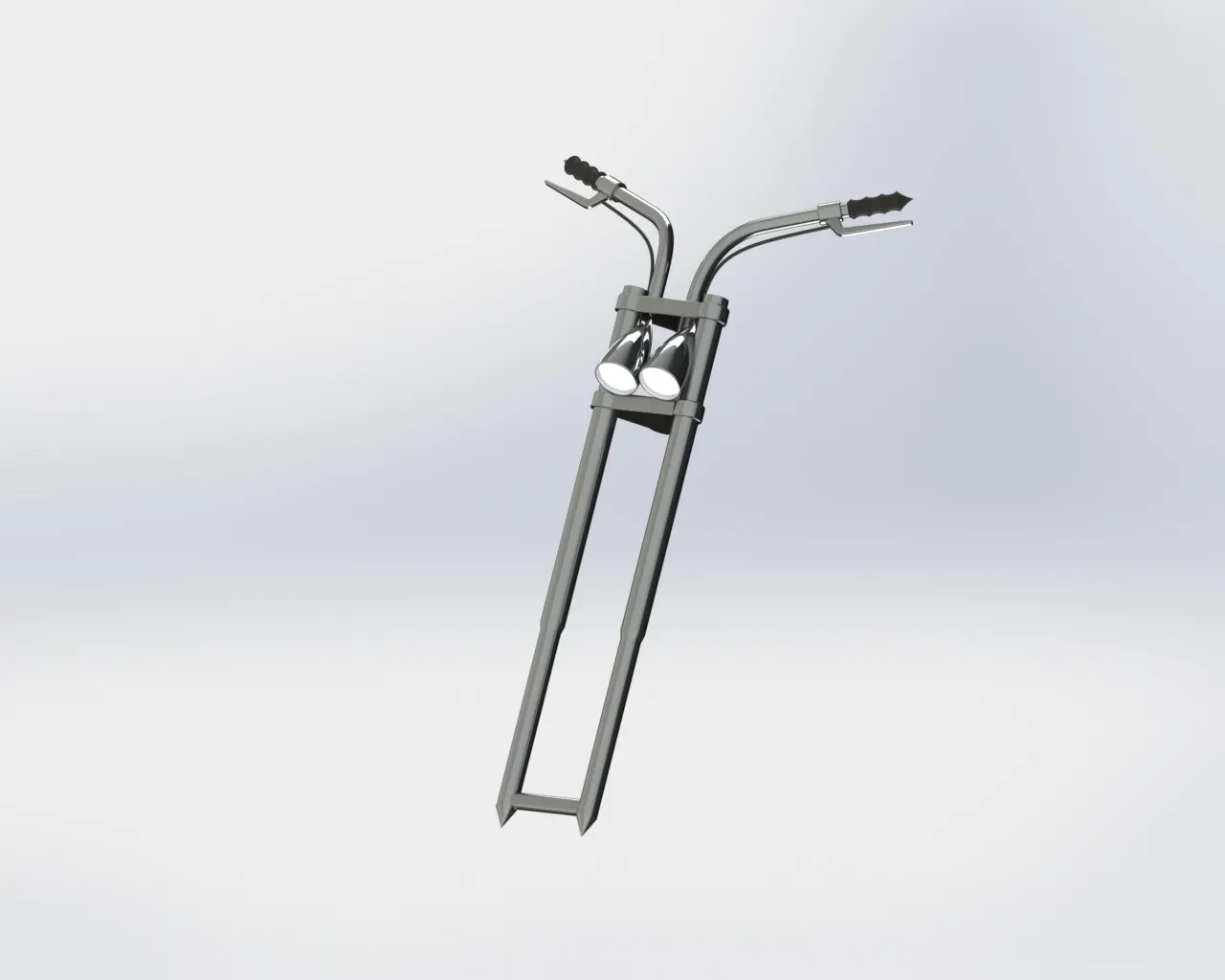
9. FRONT FORK
- Front - fork connects front wheel and chassis using a triple clamp.
- It also incorporates a suspension system, steering system and front brake system.
- Handlebars, rear-view mirror, speedometer systems, key system, etc. are assembled in the front fork.
- Front - wheel is connected to the fork using axle and nut
- Chassis is connected to fork using ball racer systems.
- Feature Tool: Extrude boss / base , dome , extrude cut , revolved cut, project curve, swept boss / base, combine, mirror and fillet.
- Sketch Tool: Sketch Geometry like line, spline, circle, convert entities and trim entities.
- Appearance: Chrome steel for fork, Matte rubber for handle and brake wire and Arial light
- Render Image: Photo View 360
Procedure for modelling rear wheel in brief
- Create a sketch of the fork tube in the front plane and revolve it.
- Create a sketch of triple clamp on the larger face of the fork tube and extrude it.
- Create a copy of the triple clamp 240 mm away from the first one.
- Create an axle at the bottom side of the fork tube.
- Create a steering stand on the upper face of the lower triple stand.
- Create a sketch of a headlight and revolve it and move it to the appropriate position.
- Create a cut portion on the headlight for good visualisation.
- Create handlebar using curve projection and sweep options.
- Create a sketch for making handlebar grip and revolve it.
- Create a sketch for brake lever and extrude it.
- Using project curve option, create a curve for making cables.
- Mirror all the parts along an appropriate plane
- Combine the required parts.
- Apply the material to all the individual parts separately and save the file.
-
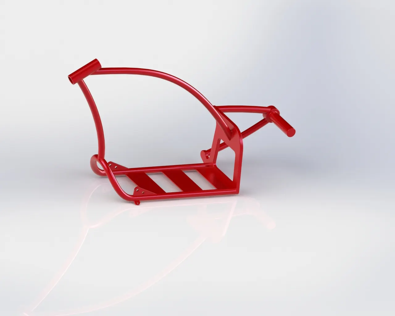
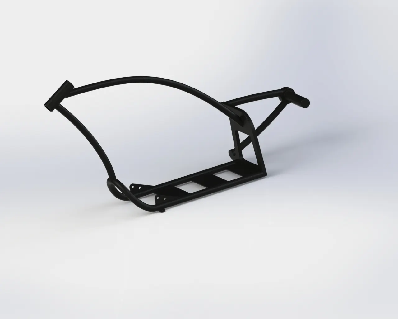
10. CHASSIS
- Chassis is a physical frame or structure of an automobile in which all the necessary components are assembled.
- There will be no relative motion on the chassis.
- Common materials used for making chassis of automobiles are carbon steel and aluminium alloy.
- There will be separate slots and provisions on the chassis for placing all the components.
- Cylindrical pipes or rods are usually used for making chassis.
- Feature Tool: Extrude boss / base, dome, extrude cut, revolved cut, project curve, swept boss/base, Revolve boss/base, combine, mirror, Chamfer and fillet.
- Sketch Tool: Sketch Geometry like line, 3-point arc, spline, circle, convert entities and offset entities.
- Appearance: Greasy Grey.
- Render Image: Photo View 360
Procedure for modelling chassis in brief:
- Insert the image of the chopper and place it accordingly with appropriate transparency.
- Draw the sketch of circular profile required for sweeping.
- Using project curve option, draw a curve by sketching two curves in mid - plane and bottom - plane.
- Sweep the circular profile through curve created in the previous stop.
- Draw the sketch of the back portion of chassis in right - plane and extrude it.
- Provide fillet to all the required edges.
- Draw a sketch of the cross - section of the chassis bar and sweep it through the curve, created using projection curve at all the required portions.
- Using the split option removes all the extra material from the chassis.
- Create a sketch of the bottom portion of the chassis and extrude it.
- Create a sketch of side stand holder and extrude it.
- Provide fillet to all the required edges.
- Apply appropriate material to all the portions
-
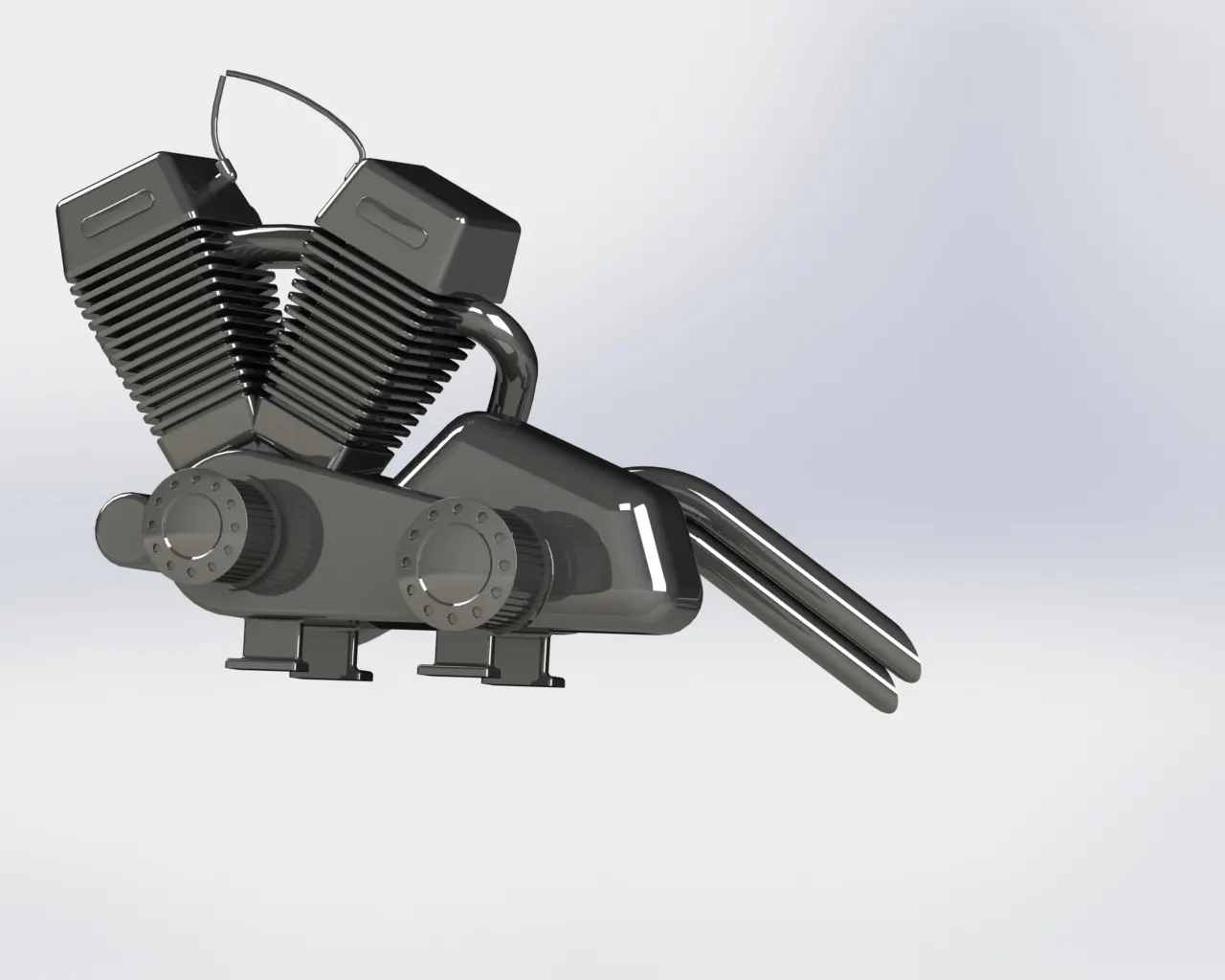
11. ENGINE
- The engine is the heart of an automobile, which generates the required motion for the vehicle.
- Engine assembly consists of a cylinder, piston, crankshaft, gearbox, camshaft, pulley system, starter motor, carburettor, spark plug etc.
- Fins are provided on the surface of the cylinder and head for heat dissipation from the surface. The transmission belt is placed in between two pulleys. The chain is connected in between sprockets provided in the engine and rear wheel.
- Most of the parts in the engine are made using aluminium and its alloys.
- Feature Tool: Extrude boss / base, dome, extrude cut, revolved cut, project curve, composite curves, swept boss / base, Revolve boss / base, combine, mirror, Chamfer and fillet.
- Sketch Tool: Sketch Geometry like line, 3 point arc, spline, circle, convert entities and offset entities.
- Appearance: chrome steel
- Render Image: Photo View 360
Procedure for modelling Engine in brief:
- Insert the image of the chopper and place it accordingly with appropriate transparency.
- In the front - plane draw the sketch of the bottom portion of the engine and extrude it.
- In the front - plane draw the sketch of the lower portion of the engine and extrude it.
- Draw the sketch of side - view of both the pulleys and sweep it.
- Provide dome on the outer surface of the pulleys.
- Provide holes on the outer surface of both pulleys and extrude it . Also using curve pattern distribute it along the curved surface.
- Provide chamfer and fillet to required portions.
- Create a new plane for drawing cylinder of the engine.
- On the new plane draw the top view of the cylinder portion and extrude it.
- Provide chamfer and fillet to all the required edges.
- Draw the cross - section of the cooling fins and extrude it.
- Using curve pattern distribute it along the curved surface and apply fillet to required edges.
- Draw a cross - section of the spark plug and extrude it.
- Provide fillet to all the required edges.
- Draw the sketch of the bottom stand and extrude it.
- Draw the sketch of the sprocket and extrude it, also create teeth on the extruded portion.
- Draw the exhaust pipe curve using project curve option and sweep the circular portion drawn on the plane perpendicular to the curves.
- Create the curve of the sparkplug cable and sweep the circular section along the curve for both the sparkplugs.
- Save the file
-
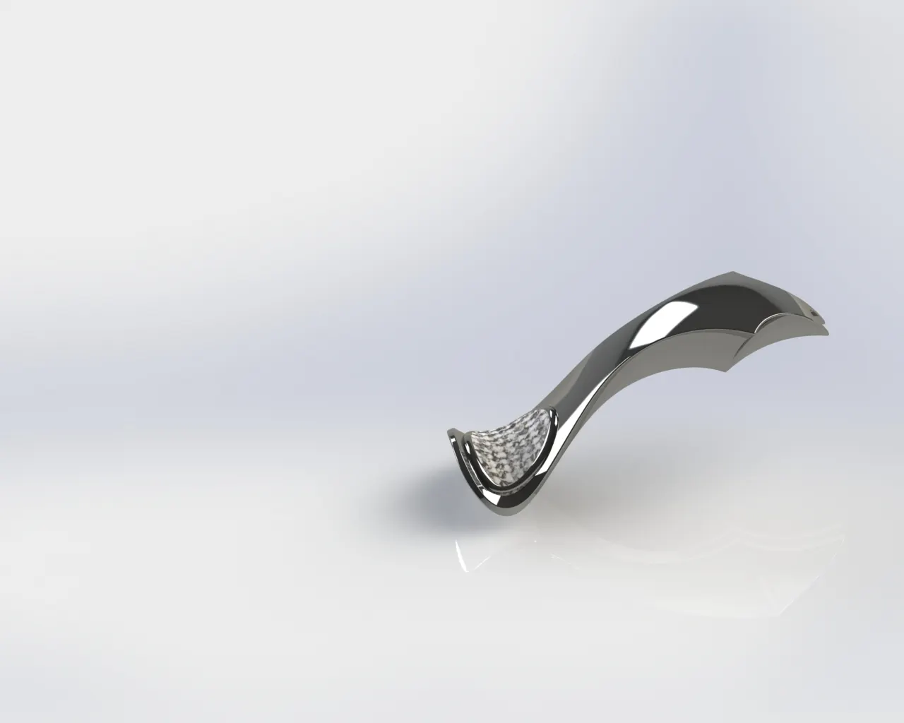
12. FUEL TANK
- Fuel tanks are basically storage tank used for storing fuel which is used in the chopper, It is placed above the engine. Capacity and shape of the tank may be different for different types of vehicles. Fuel tanks are usually made up of steel. The seat is placed on the lower part of the fuel tank.
- Feature Tool: Project curve, Swept Surface, combine, mirror, Boundary surface, knit surface, swept cut, shell and fillet.
- Sketch Tool: Sketch Geometry like line, spline, circle, convert entities and offset entities.
- Appearance: Rose Gold for gas tank and Fabric for driver seat.
- Render Image: Photo View 360
Procedure for the modelling fuel tank in brief:
- Insert the image of the assembled image of the chopper and align it on the appropriate position.
- Draw curves in required planes and project it using project curve feature.
- After creating the path curve and side view extrude it using surface loft feature.
- Using boundary surface feature close the open boundaries and mirror the developed surface along mid - plane 5. Combine all the surface created using the knit surface feature.
- Create a sketch of the seat and extrude it using surface extrude feature.
- Provide fillet to all the required edges and knit the surfaces to make it a single part.
- Apply material and provide colour to the component produced.
- Add decals on the surface of the fuel tank for better appearance.
-
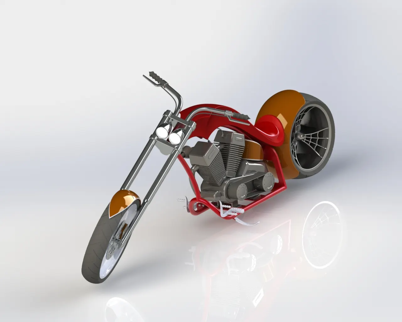
ASSEMBLING PARTS
- Combining multiple parts that fit together to create assemblies is called ASSEMBLY in SOLIDWORKS. we integrated the parts in an assembly using mate such as concentric and coincident. Mates define the allowable direction of movement of the components.
Part of the Chopper
- Chassis
- Engine
- Pedal
- Kicker stand
- Transmission belt
- Oil tank
- Rear - wheel
- Rear fender
- Chain
- Gas tank
- Front fork
- Front - wheel
- Front fender.
STEPS FOLLOWED IN ASSEMBLY OF CHOPPER
- STEP - 1: All the parts / components which are designed in the parts file are to be inserted in assembly file one by one as per requirement.
- STEP - 2: Apply mates to each individual part with other parts for proper alignment.
- STEP - 3: Apply mate's conditions to wheel and kick stand with top plane to snap it to the floor
Procedure for the Assembly:
-
- Insert chassis of the chopper and fix it.
- Insert the engine and place it over the chassis at appropriate position respective to chassis.
- Modify the exhaust of the engine for removing intersection and save the file.
- Insert pedal on the appropriate position in chassis.
- Insert kickstand in the hole provided on the chassis and provide a rotation of about 0 - 80 degrees.
- Insert transmission belt and place in between pulleys and change its dimension for removing intersections.
- Place oil tank over the engine and align it with respect to chassis.
- Place the rear wheel in the shaft provided on the chassis.
- Insert rear fender and place over the rear wheel.
- Insert chain and place it over the sprocket , also provide a slot on the chassis so as to remove the interference occurred while the chain.
- Place gas tank over the engine on the chassis.
- Insert front fork on the chassis.
- Place front wheel on the shaft in the front fork.
- Place front fender over the wheel
- Change appearance for required parts and save the fil
-
-
-
-
-
- e.
- e.
-
-
-
-