Photo Realistic Rendering
MODELING, ASSEMBLY, PHOTOREALISTIC RENDER OF AN AMERICAN CHOPPER ON SOLIDWORKS.
Objectives:
- Createing individual parts of chopper using solidworks.
- Assembling all the individual parts into chopper.
- Knowing the application of decals,lights and camera.
- Creating photorealistic model and render it using photoview 360 and solidwork visualize.
Introduction:
Solidworks is one of the prominent modelling software avaliable today this software is mainly used to model 3D parts using 2D sketch.It also has the option to specify the material and look of the model which we created.It has other ADD-in features like photoview360 which helps in rendering of the final model to make it look photo realistic. In this project we learnt about detailed design of Americal chopper parts and assemblig them and rendering the final after assembly.
Methodology:
All the parts for the assembly of the chopper were made separately first and then were assembled in Solidworks.
Description:
Components of the American Chopper:
- Transmission Belt
- Kickstand
- Front Fender
- Rear Fender
- Front Wheel
- Rear Wheel
- Chain
- Oil Tank
- Gas Tank
- Engine
- Chassis
- Pedal
- Pedal LH
- Front Fork
Details of SOLIDWORKS Features Used :
Sketch:
The sketch is used to create the 2D representation of model. In solid work there are different entities are available like as follows:
- Line
- Circle
- Arc
- Spline
- Rectangle
- Polygon
- Fillet
- Ellipse
- Offset - The offset command create parallel line, curve, and concentric circles through a point or at a specified distance.
- Trim and extend entity - The trim command is used to remove the selected extra line/parts of an object. And the extend command is used to extend the selected boundaries or edges.
- Covert entity - It is used to project the last sketch in to the current sketch plane.
- Mirror - Mirror is used to create remaining half of a sketch/ copy of selected sketch about a specified line.
- Linear sketch pattern - It is used to create multiple instance of feature that can uniformly specified along one or two linear paths.
- Smart dimension - It allows you to dimension the part which is created.
- Dynamic mirror - Select the dynamic mirror feature to mirror pre-existing sketch. First select line, centerline, and linear model edge about which to mirror, and then create a sketch to mirror.
Extruded boss/base:
It is used to convert 2D sketch into 3D model in one or both directions from sketch plane. Here you have to specify direction up to surface, vertex, value, body from sketch plane.
Extrude cut:
It helps to remove material from the created 3D model by using 2D sketch. It is opposite of extrude boss/bass feature. Here also you have to specify direction up to surface, vertex, value, body from sketch plane.
Revolved boss/base:
It is used to revolve a 2D sketch (one or more profile) along a axis, line or centerline.
Revolved cut:
This feature is just opposite of revolve boss/base. The revolved cut allows to cut a profile around an axis, plane, and line to create complex geometry.
Swept Boss/Base:
A swept feature is used to create a solid body by moving a closed entity/ profile along specified sketch/path. In order to complete a feature, two sketches are necessary. One will be the closed profile and second will be the path.
Swept Cut:
A swept cut feature allows to cut a 3D model by sweeping a closed sketch profile along a specified path sketch. The path sketch will control the direction of cut. Profile sketch should be connected to the path sketch.
Lofted boss/base:
The loft feature creates a solid body by making transition between multiple profile and guide curve. It helps to generate complex geometry in one feature.
Lofted cut:
The loft cut is allows to remove material between two sketch profiles. Make sure that selections are must under the profile selection box and not the guide curve selection box
Fillet:
It is used to create a rounded shapes at internally or externally faces of the part. There are different types of fillet:
- Constant Size fillet
- Multiple radius fillet
- Round corner fillet
- Setback fillet
- Variable size fillet
- Face fillet
- Full round fillet
- Asymmetric fillet
Chamfer:
This feature is creates a cut on selected edge, face or a vertex. Types of chamfer:
- Angle –Distance- Enter the values of distance and angle in the chamfer parameter box.
- Distance- Distance- Enter the values for both distances in the chamfer parameter box or on the side of selected edges.
- A vertex- Enter values for the three distances on each side of selected vertex.
Patterns:
- Linear pattern – To create multiple instances of one or more feature to that can space uniformly along specified path, plane.
- Circular pattern – To create multiple instances of one or more feature to that can space uniformly along an axis, line.
- Curve Driven Pattern – To Curve creates multiple instance of one or more feature to that can space uniformly along 3D curve (open or closed curve).
Shell:
It is used to define the thickness of wall, hollows out a part, leaves open the selected faces. Shell may be with uniform or multiple thickness faces.
Dome:
Dome features is used to one or more dome on the same model in one feature.
- Face to dome - Used to apply dome to faces whose centroid lies outside the face.
- Elliptical Dome -Used to apply dome for cylindrical/ conical model.
Split:
Split feature is used to create multiple body or surfaces from one part/ surface. In the trim tool box we need to select sketch and click on cut part. In this feature we can create multiple body or consume cut bodies.
Combine:
There are three different options are available to use combine feature.
- Add-To merge multiple bodies together into one.
- Subtract-To remove multiple bodies from main body.
- Common- To add two bodies together and keep the area that is common to them.
Feature description for surface Modelling:
Surface modelling is used to build out a represent of solid objects exterior and it’s a contours. Following feature are used in design of seat, gas tank of chopper.
Swept Surface:
The surface is created by sweep profile and sweep path.
Lofted Surface:
The surfaces are generated by multiple 3D curves / existing edges. There should be a tangency between the selected curve/edges.
Boundary Surface:
The boundary surface creates surfaces that can be tangent or curvature continuous in both direction. In most of cases, we get high quality result as compare to lofted surface.
Filled Surface:
The feature create a surface to fill the gap in a model.
Surface Trim:
It is used to cut away material from a surface.
Extend Surface:
This feature extend the surface by selecting as edge, multiple edges or a face.
Surface Knit:
The surface knit feature combine multiple faces and surfaces into one. Surface edges must be adjacent and not overlapping.
Appearance:
An appearance is define the visual properties of model which include color and texture. We can apply appearance to the individually to the complete model / one or more face /edges .It does not affect on physical property which are defined by material.
Description of American chopper parts and used features in detailed:
The assembly consists of 14 parts as per below:
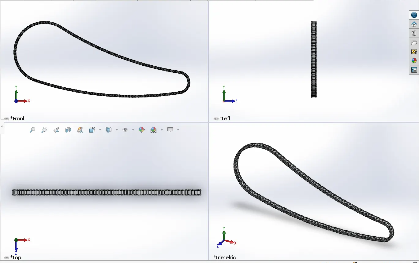
- CHAIN:
Features used:
- Curve Pattern - It allow to pattern solid bodies along a curve path at required instances.
- Block - Sometimes we need a single sketch multiple times. We can convert such a sketch into block at add it whenever require.
- Mirror.
- Extrude.
- Fillet.
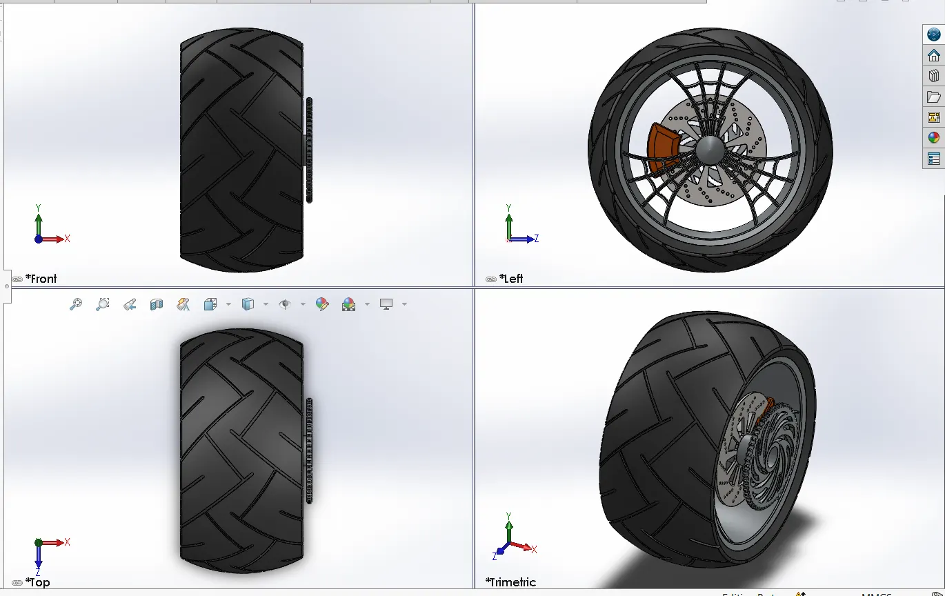
- REAR WHEEL&FENDER:
Features used:
- Combine - It allows combining two or more solid bodies.
- Circular pattern - It is used to pattern the feature circular at require instances.
- Chamfer - It creates sloping surface at solid bodies corner or edges.
- Extrude boss.
- Extrude cut.
- Revolve.
Features used:
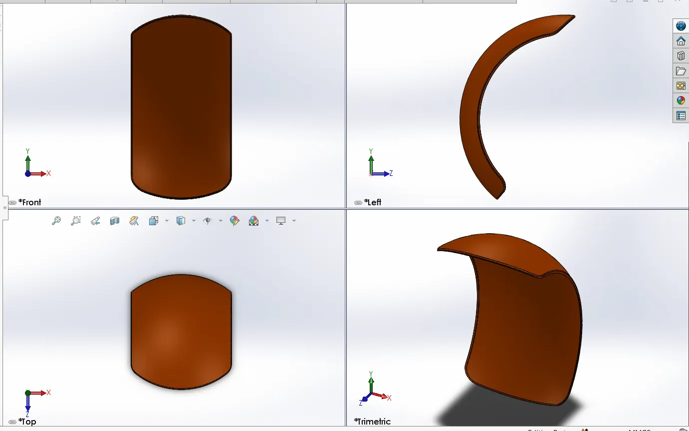
- Shell - This feature hollows out part, leaves open the faces selected and creates thin walled feature on remaining faces. Also, it creates closed hollow model.
- Revolve
- Split
- Fillet
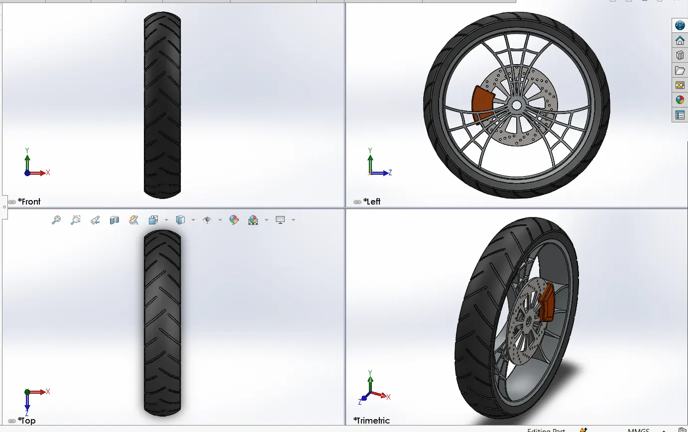
- FRONT WHEEL&FENDER:
Features used:
- Combine - It allows combining two or more solid bodies.
- Circular pattern - It is used to pattern the feature circular at require instances.
- Chamfer - It creates sloping surface at solid bodies corner or edges.
- Extrude boss.
- Extrude cut.
- Revolve.
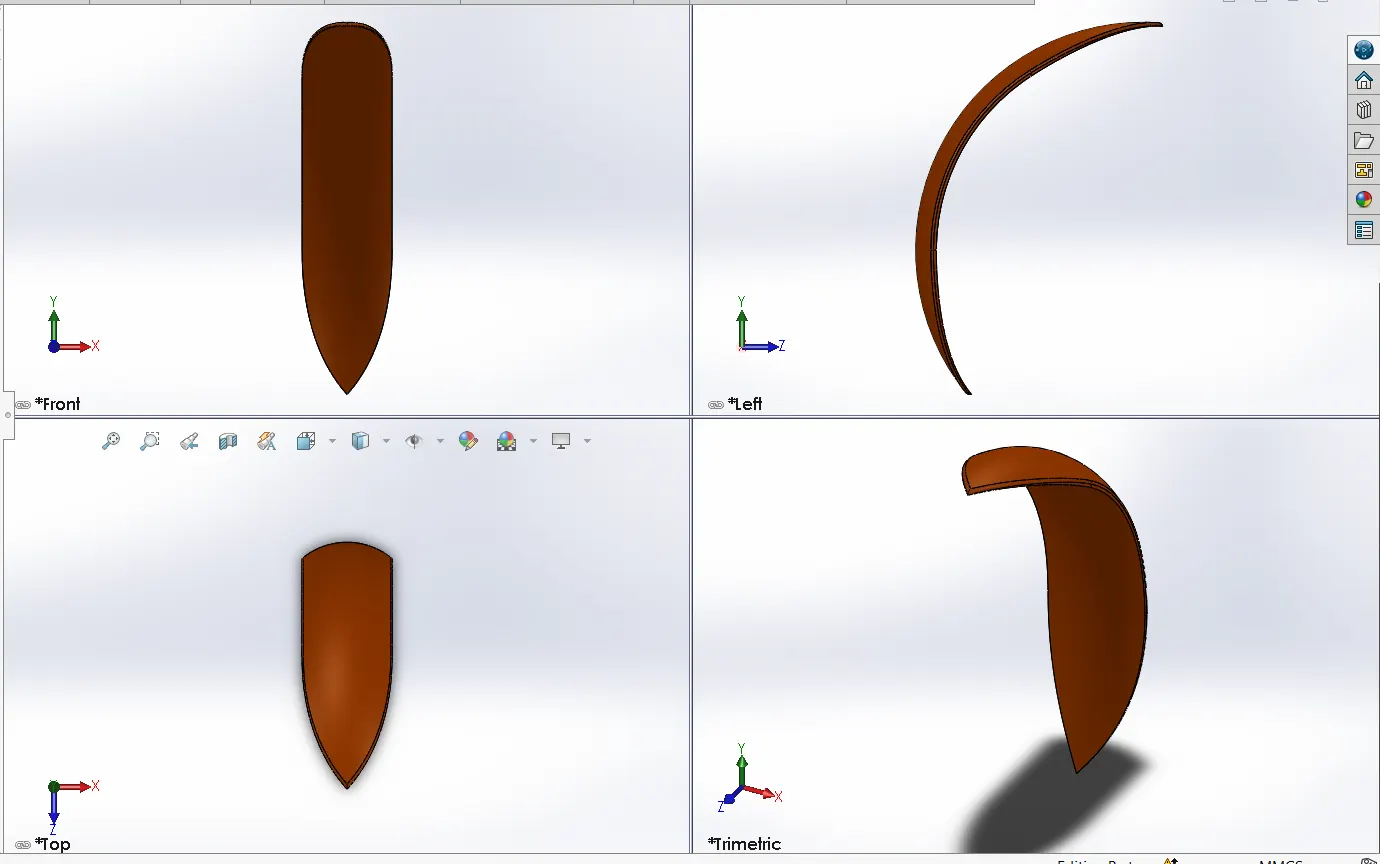
Features used:
- Revove- Any profile can be revolved about an axis, centre line or edges and obtain solid bodies from 0 degrees to 360 deg.
- Dynamic mirror- In this you can mirror any sketch or entities about pre-selected sketch or entity.
- Offset entities.
- GAS TANK:
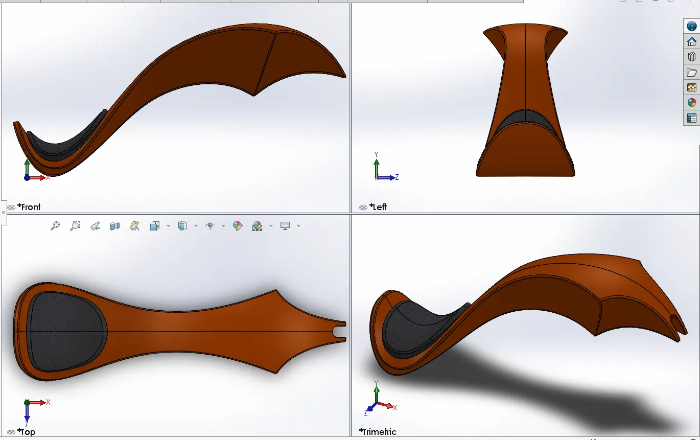
Features Used:-
- Sweep surface - It genearates surface from section curve positioned along a path.
- Loft surface - It create surfaces between existing edges by creating smooth tangency between selected curve.
- Extrude surface - It convert projected surface into 3d surface.
- Boundary surface - This feature create surface between boundaries or edges but specifying both direction.
- Surface Knit:- This feature is use to combine two or more surfaces to make one solid body surface.
- Surface Trim - It is use to remove unnecessary surface.
- Sweep cut - It is use to cut solid bodies along a path.
- Fillet.
- Shell.
- Mirror.
- CHASSIS:
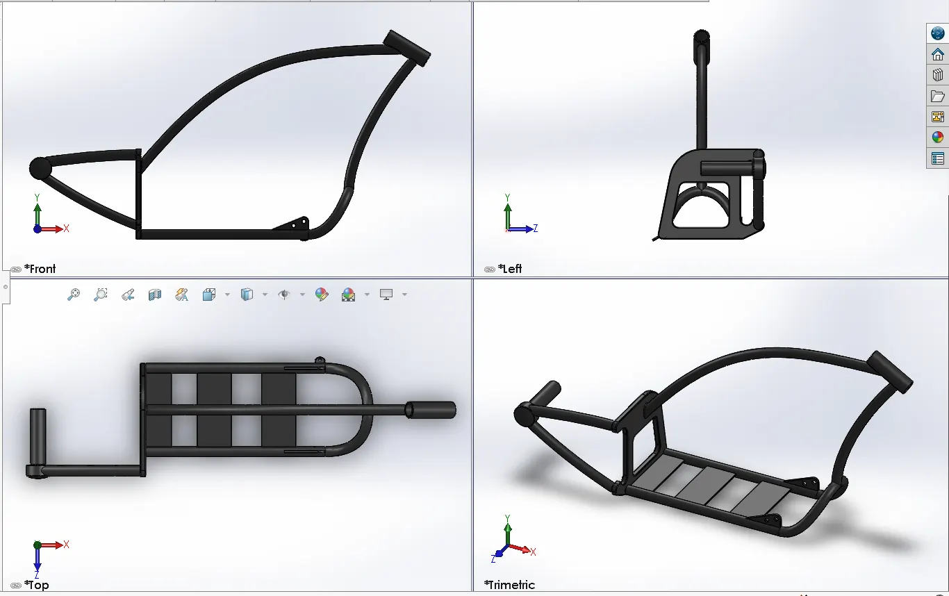
Features Used:
- Project curve.
- Sweep.
- Mirror.
- Extrude.
- Combine.
- Revolve.
- Fillet.
- Plane.
- Dome.
- Split.
- FRONT FORK:
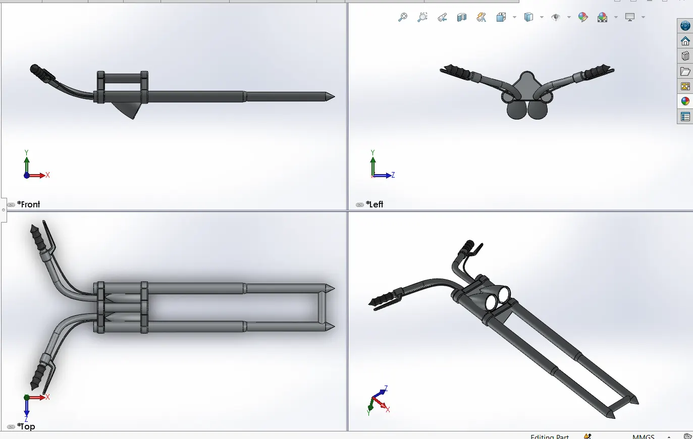
Features used:
- Project curve - It helps to get 3d curve which is projected on the basis of two 2d sketches.
- Sweep - This feature creates solid body from 2d sketch profile along a 3d curve.
- Move - It help to move any object.
- Mirror - It helps to mirror half portion of fork to complete the fork.
- Extrude.
- Combine.
- Revolve.
- Fillet.
- Plane.
- Dome.
- Linear Pattern.
- ENGINE:
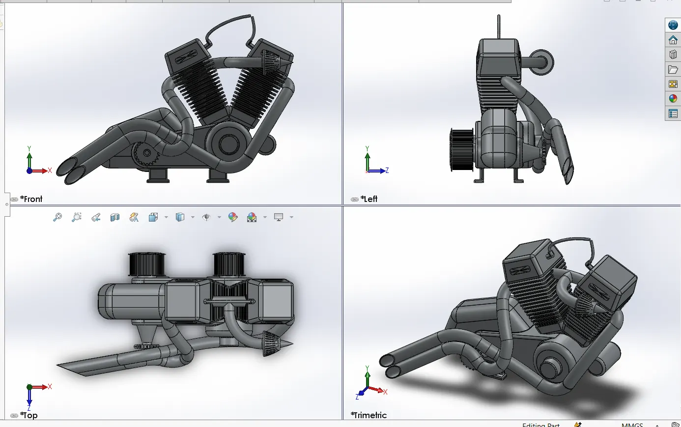
Features Used:
- Composite Curve - It help to combine two 3d curve.
- Extrude cut.
- Plane.
- Offset.
- Circular pattern.
- Linear Pattern.
- Sweep.
- Mirror.
- Project curve.
- Extrude.
- Combine.
- Revolve.
- Fillet.
- Plane.
- Dome.
- Split.
- TRANSMISSION BELT:
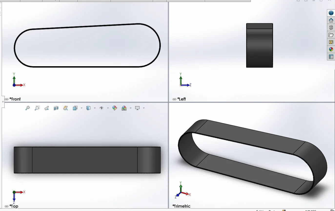
Features used to create transmission belt:-
- Extrude- This feature is used to convert 2d sketch into 3d object.
- Fillet - This feature is used to convert external and internal edges into rounded shape.
- Offset entities - It is used to create same entities on some distance.
Procedure:-
- Draw the fully defined sketch of require dimension on front plane using line and arc option. Then offset the sketch on some distance to create thickness of belt.
- Then extrude command is used to convert 2d sketch into 3d.
- Fillet is applied as per requirement to sharp edges.
- Model is fully defined and should be saved.
- KICKSTAND:
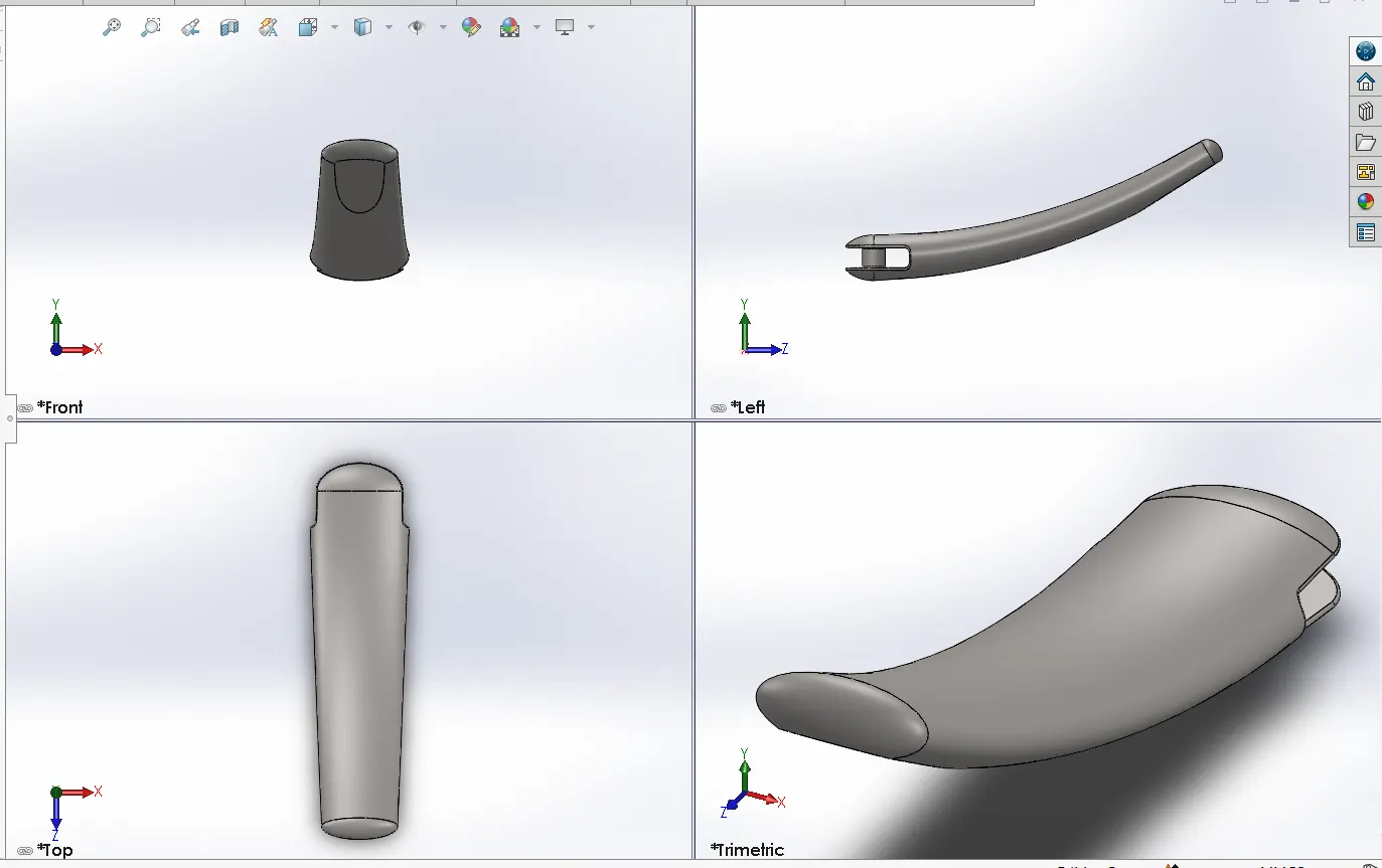
Features Used:
- Extrude boss- This feature is used to convert 2d sketch into 3d object.
- Fillet
- Loft- It determines the profiles used to create a loft. Select sketch profiles, faces or edges to connect. Lofts are created based on the order of profile selection.
- Dome- This is used to apply dome shape to faces. This allows you to apply domes to irregularly shaped contours.
- Split- This feature is use to split the solid bodies, surfaces and allow us to remove unnecessary portion.
- Extrude cut- It help to remove the material from solid bodies.
- OIL TANK:
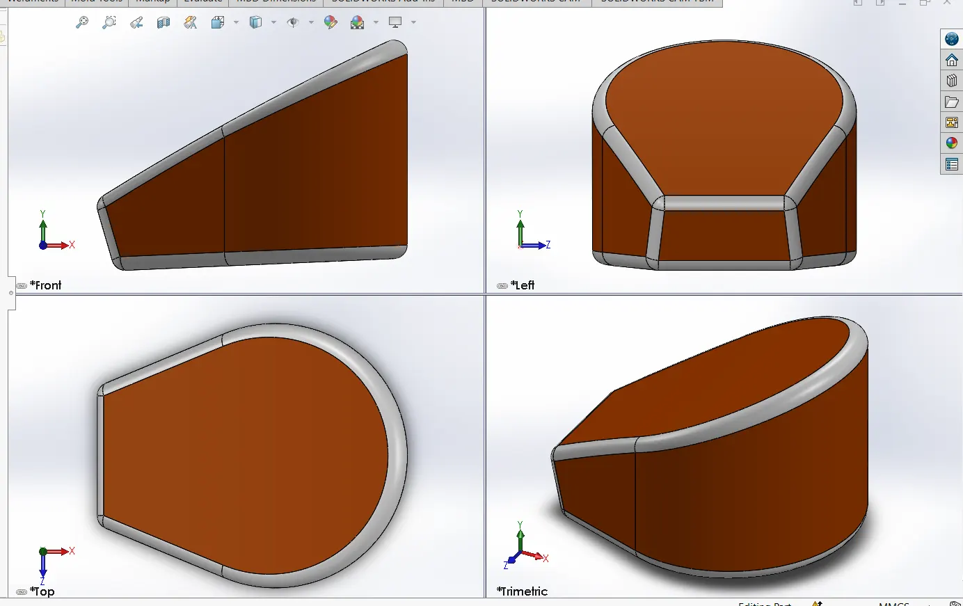
Features used:
- Extrude.
- Shell.
- Fillet.
- Combine.
- PEDALS:
RIGHT SIDE:
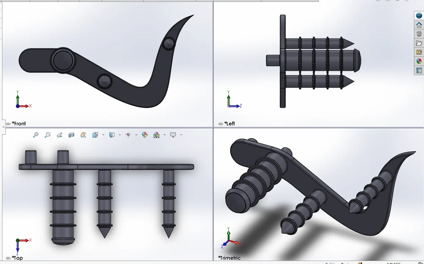
LEFT SIDE:
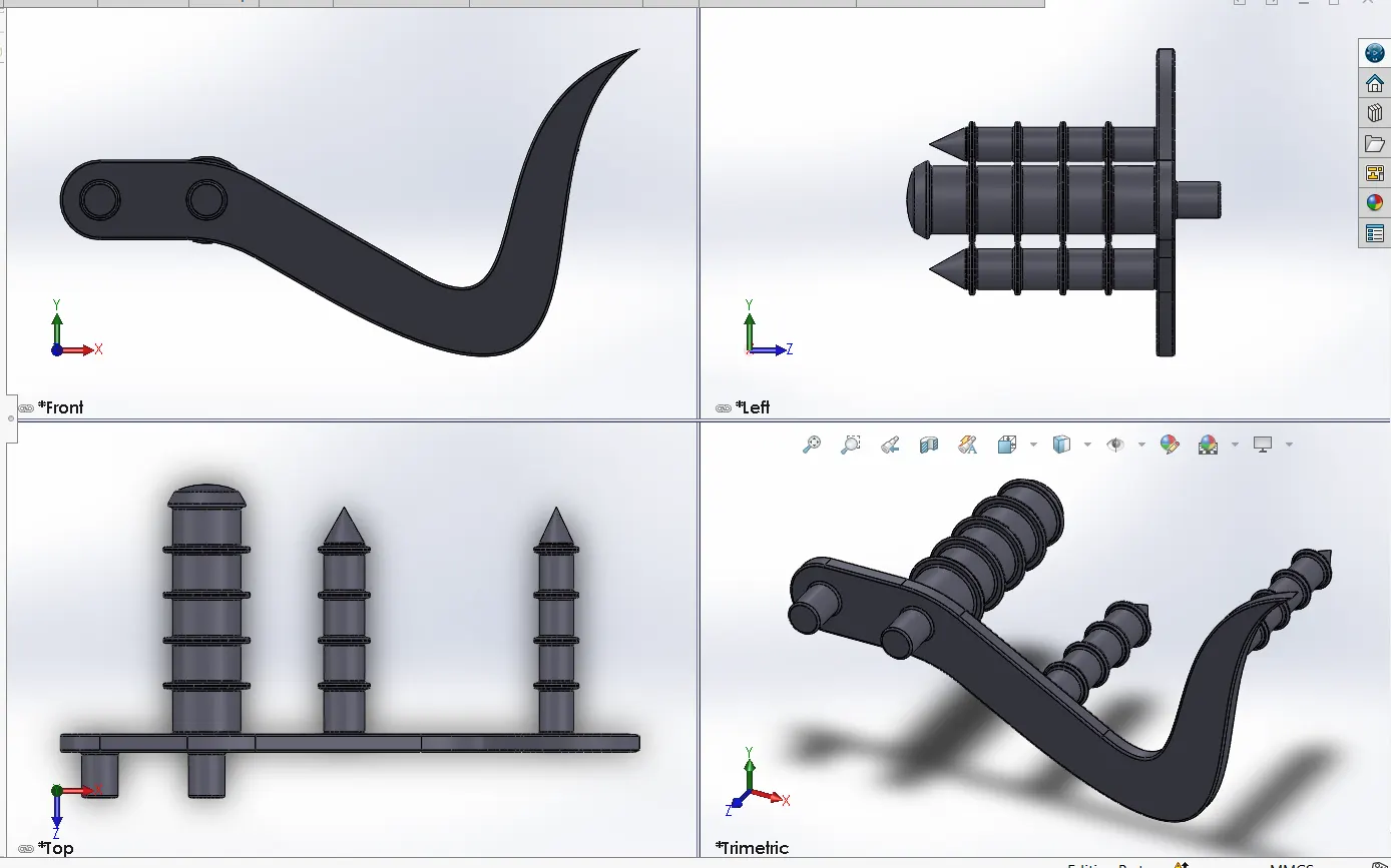
Features used:
- Linear pattern - This pattern is same like circular pattern. But it works like its name linearly along a line, centerline or edge at require instances.
- Revolve.
- Extrude boss.
- Fillet.
- Dome.
- Chamfer.
Assembly of the American Chopper:
- All the parts which are designed in the parts file are to be inserted into the assembly file one by one as per the requirements.
- And then apply mates to each individual part with other parts for proper alignment.
Features used for assembly:
- Insert part.
- Mates.
- Mirror.
Mates - It is use to provide relation between part as per their working principle. We have to define the mates as per present condition and whatever look we require.
Relations used in mates:
Coincident, Parallel, Concentric, Angle, Tangent, Width Mate.
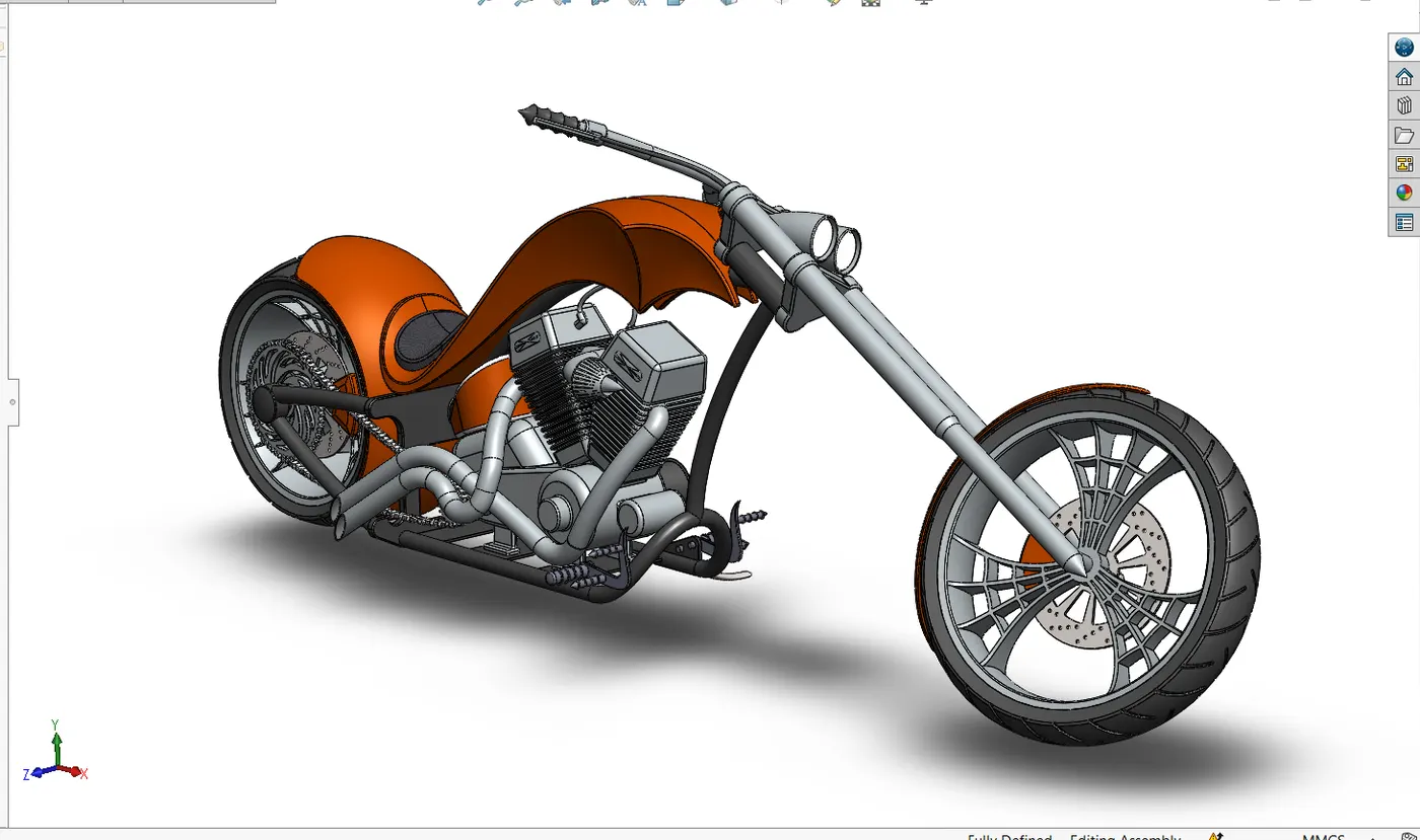
The final model:
American Chopper:
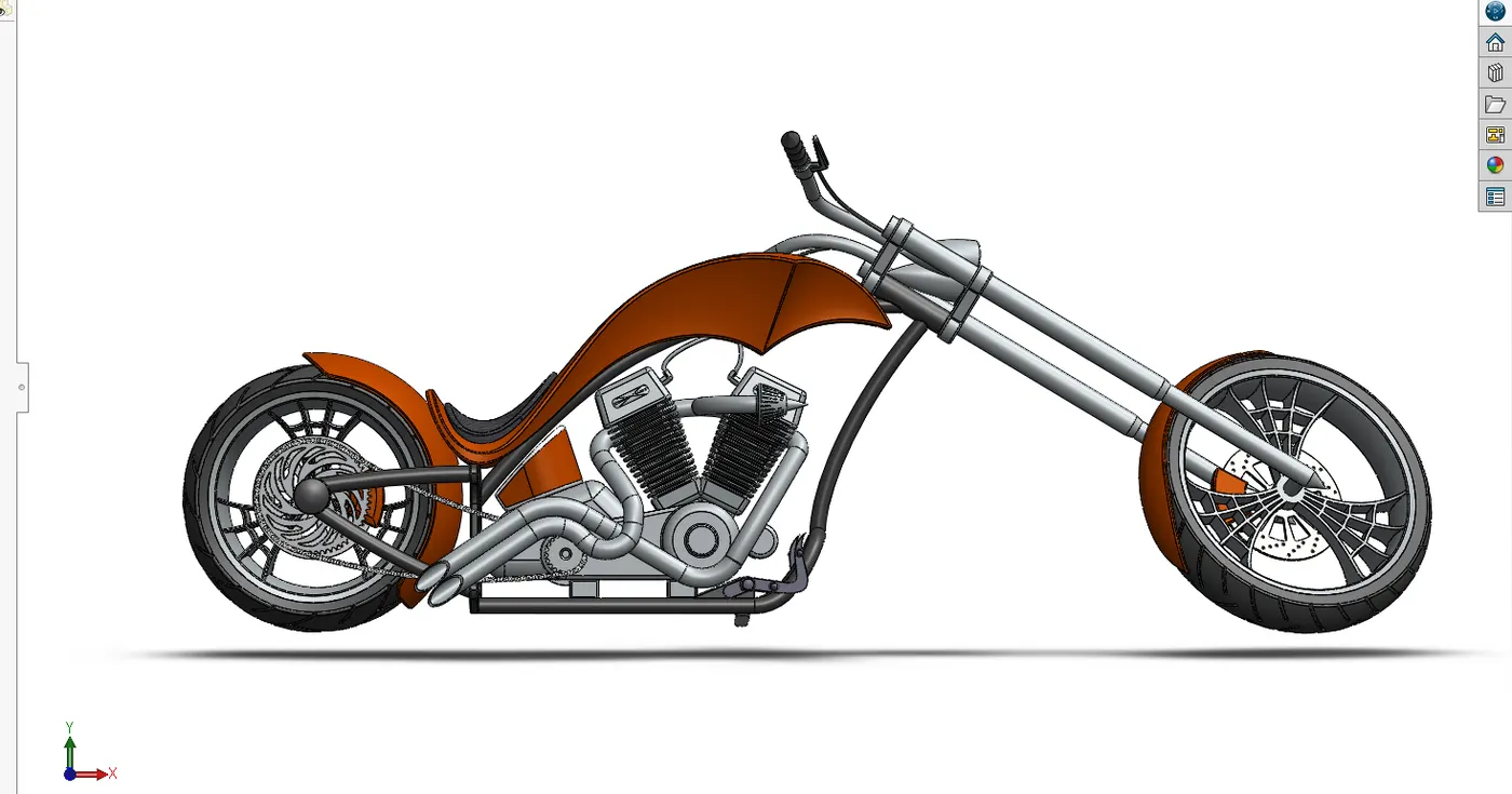
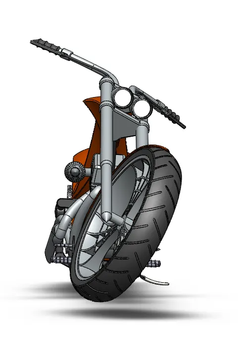
Front view:
Top view:
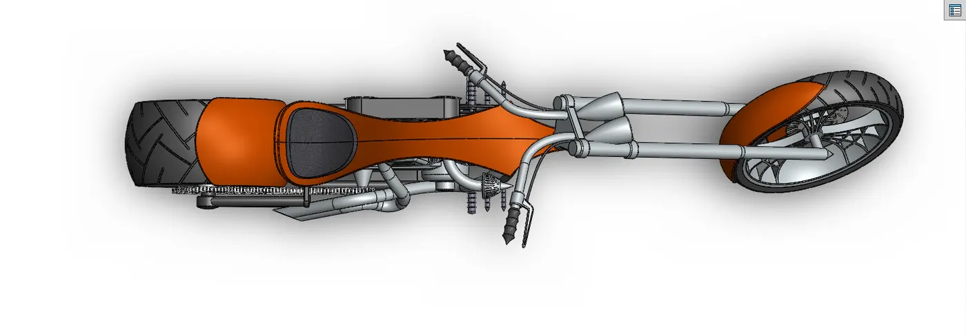
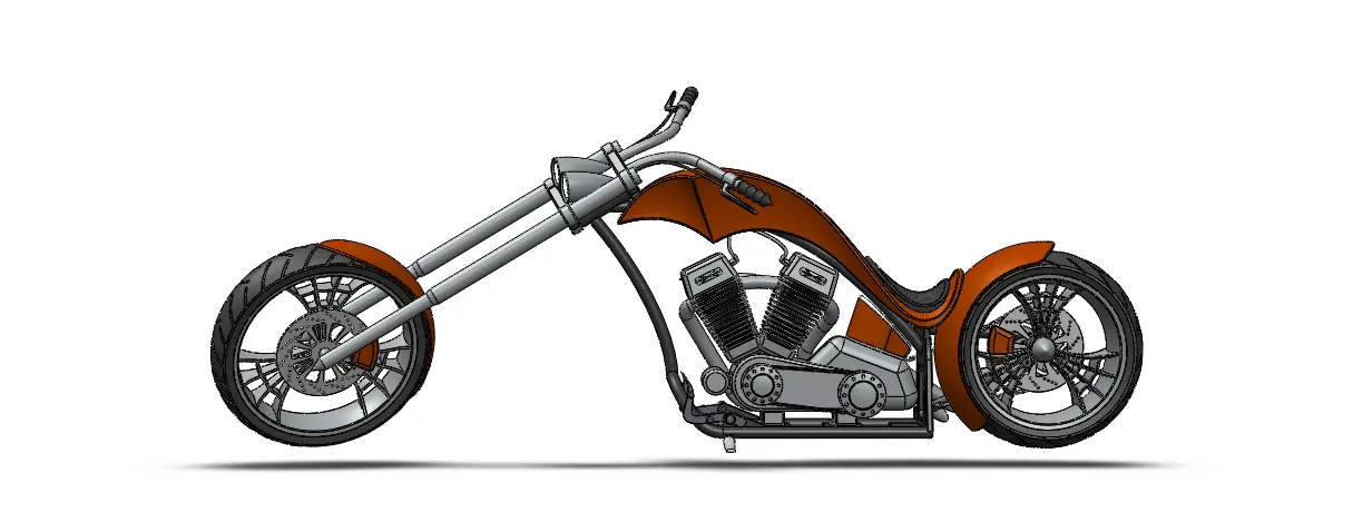
Left view:
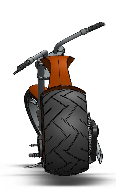
Right view:
Back view:
Bottom view:
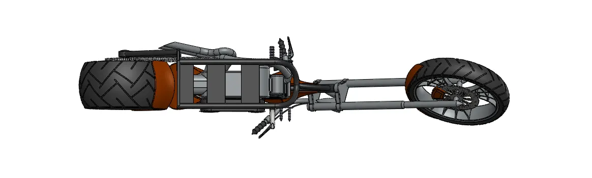
Isometric with appearence:
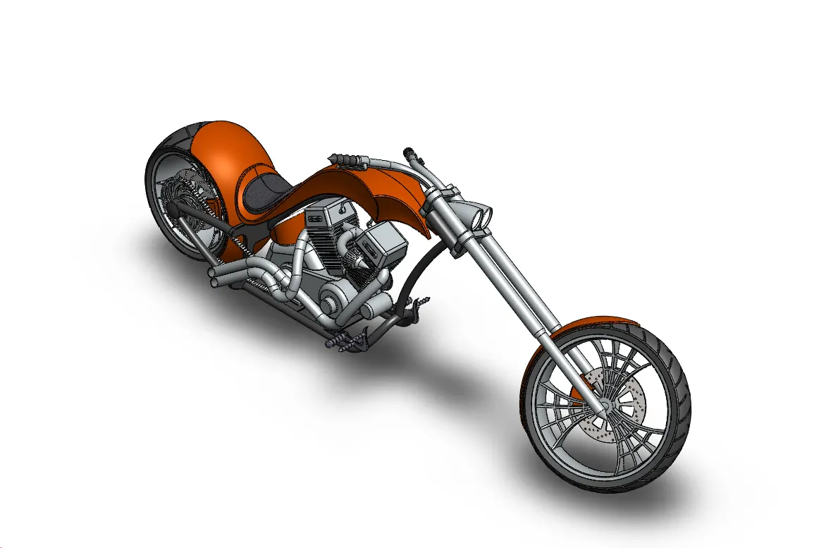
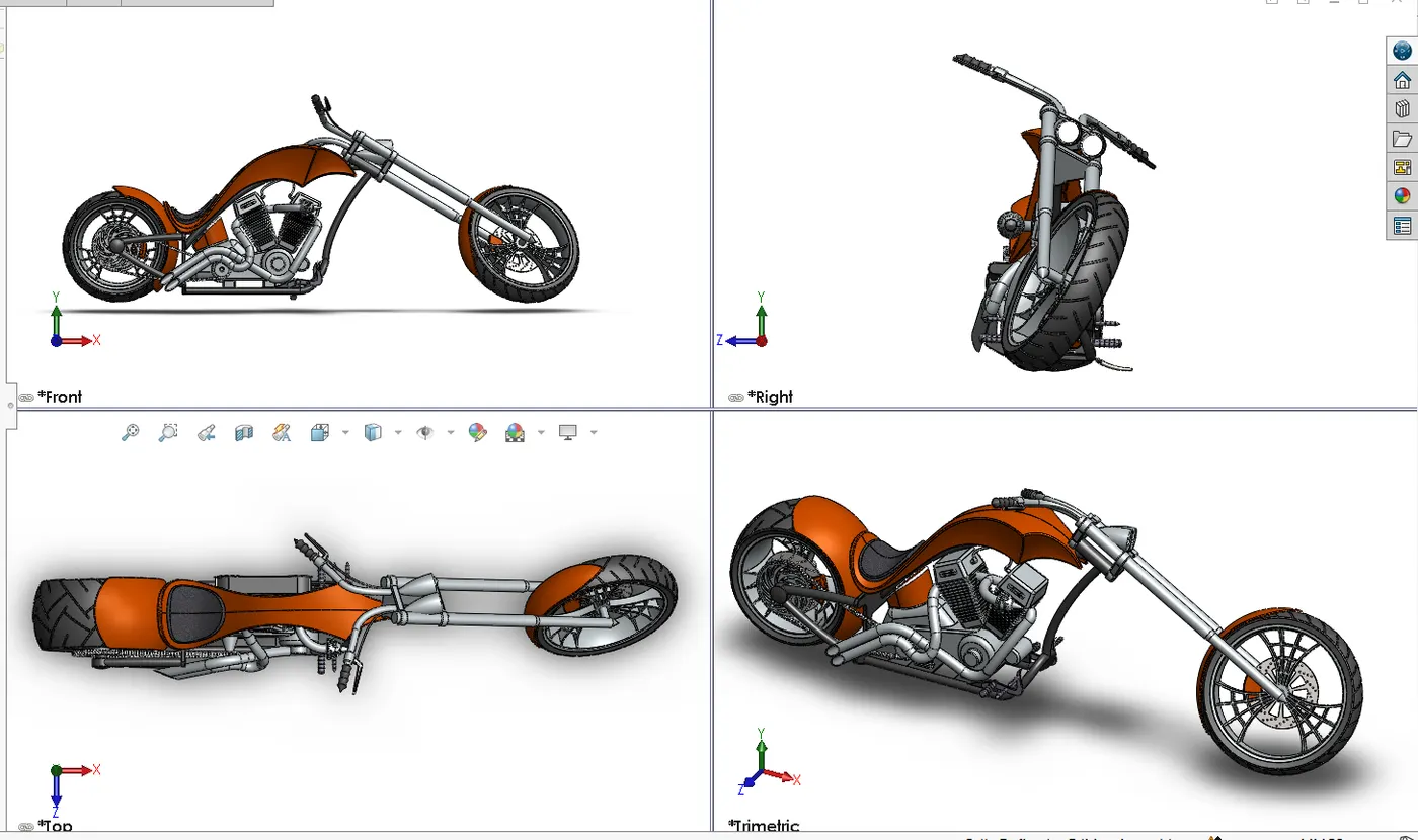
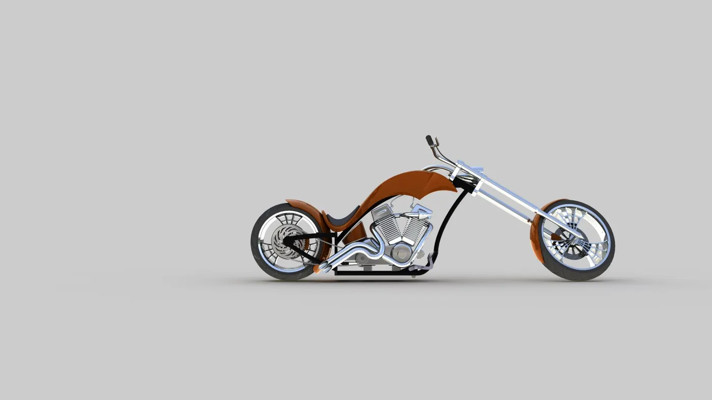
Photo Realistic Rendering on Photoview 360:
Rendering is the process of creating realistic image model in real world environment.
Rendering can be done by 2 ways - Photoview 360 and Solidworks Visualize.
As I didn't got the access request accept for the google drive link to download and add the decals, I rendered it whithout adding the decals.
Following are the rendered images in Photoview 360:
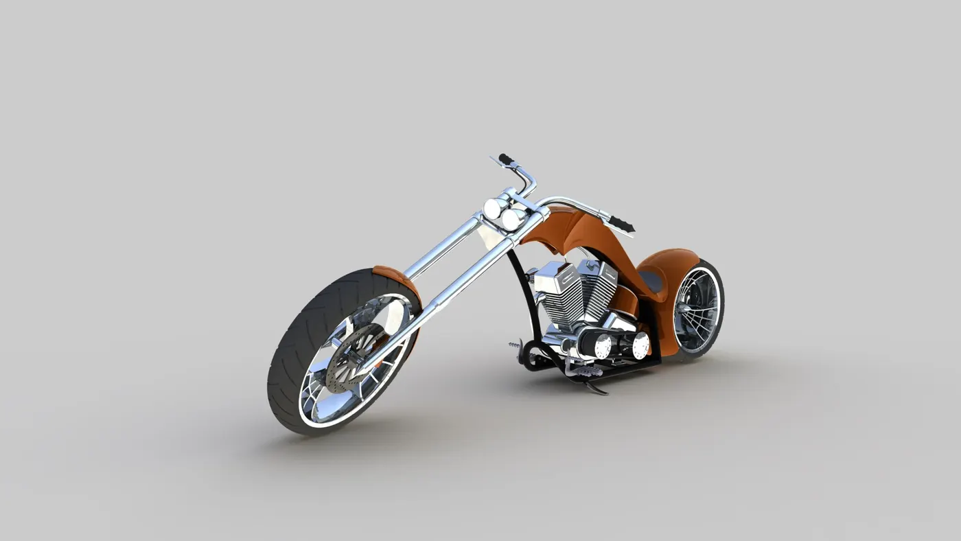
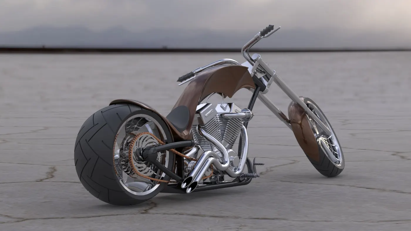
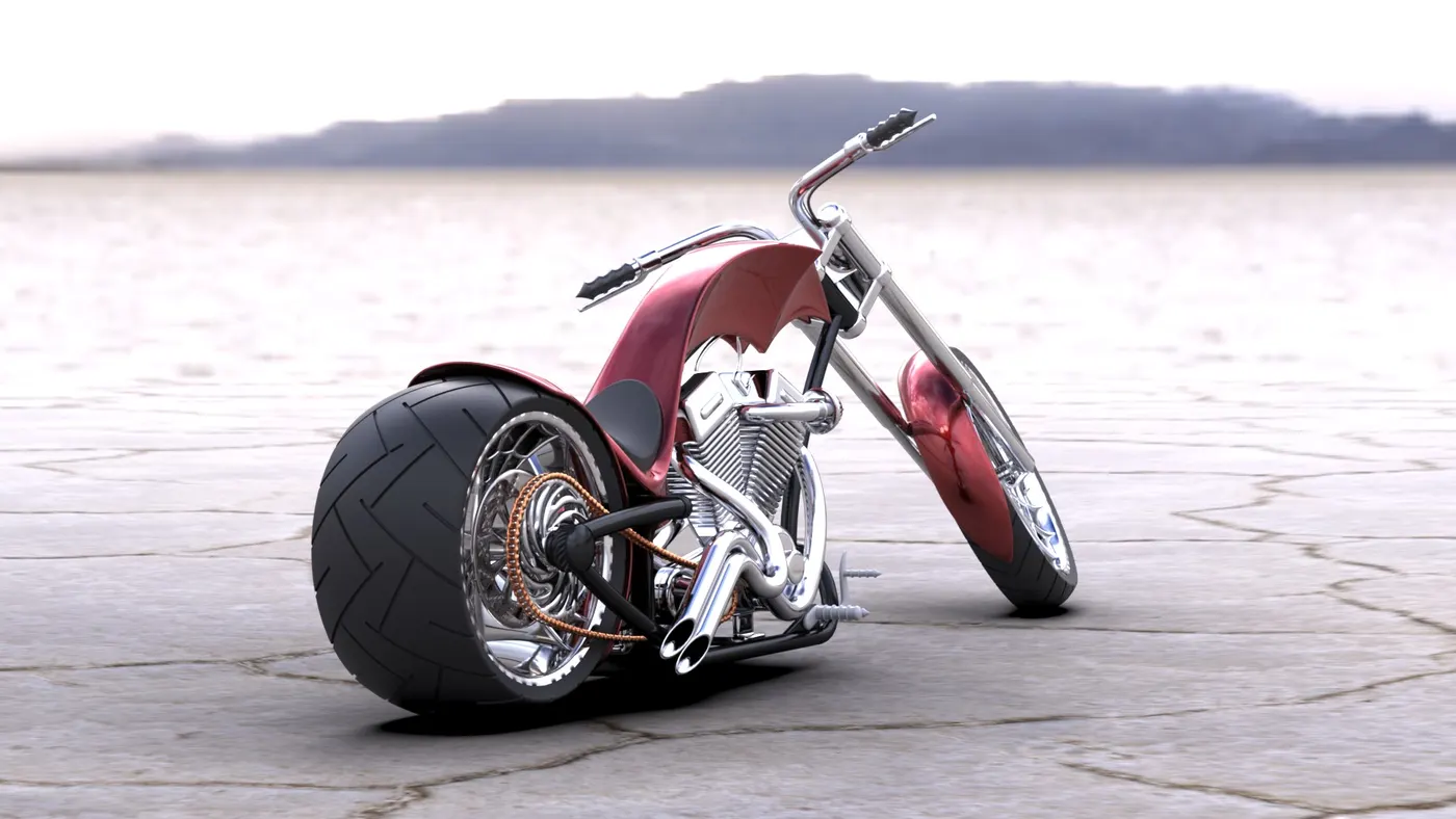
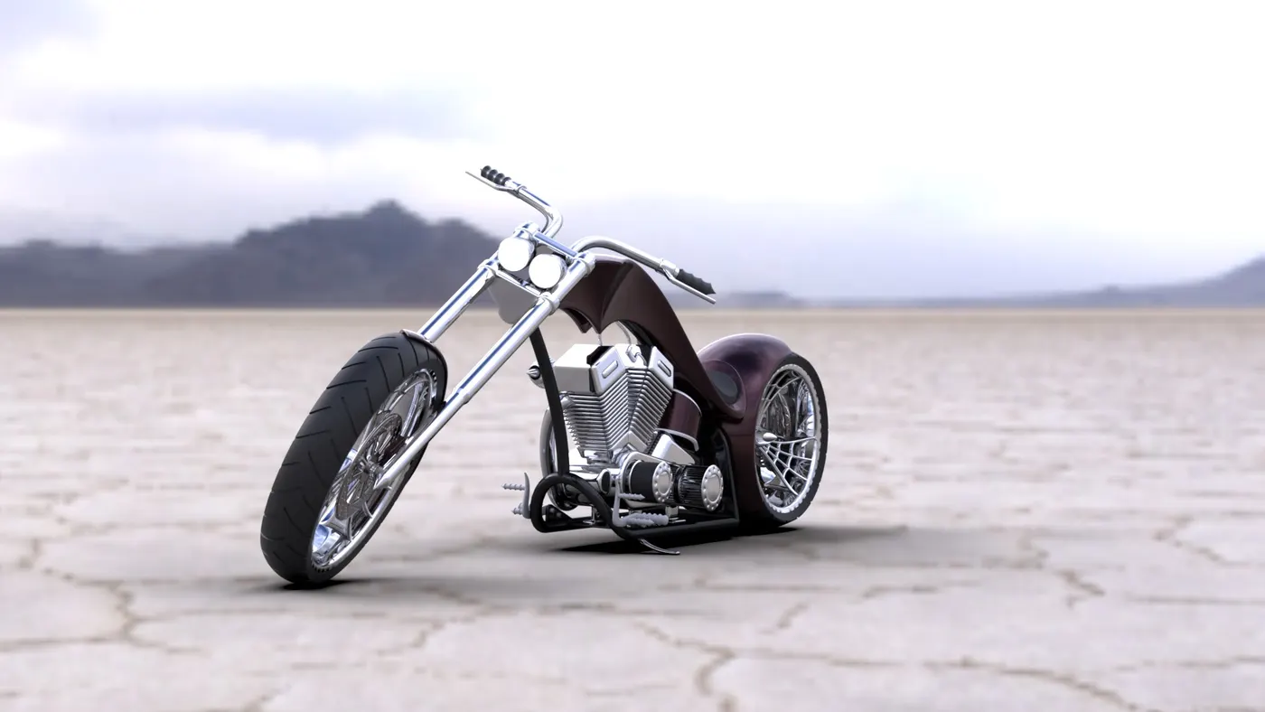
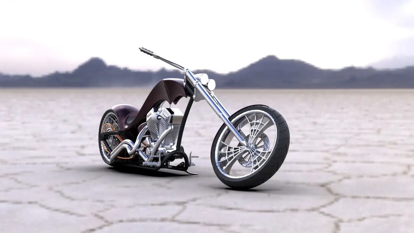
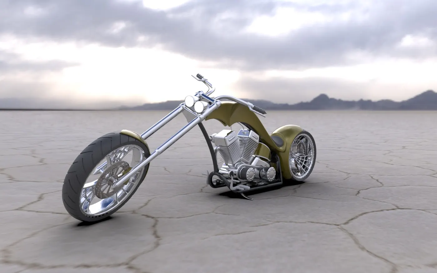
Rendering of American Chopper on Solidworks Visualize:
SOLIDWORKS Visualize allows you to leverage your 3D CAD data to create photo-quality content in the fastest and easiest way you can from images to animations, interactive web content, and immersive Virtual Reality. Bring your products to life. SOLIDWORKS Visualize is the “camera” for your CAD data.
Steps to follow in SOLIDWORKS Visualize to render image:
- Import the assembly file into the Solidworks Photo Visualize.
- Give the appearance to parts to make it more realistic.
- Add Scenes as the background
- Make a fast Rendering and check the output.
- Make a accurate rendering with grater resolution and different color combinations.
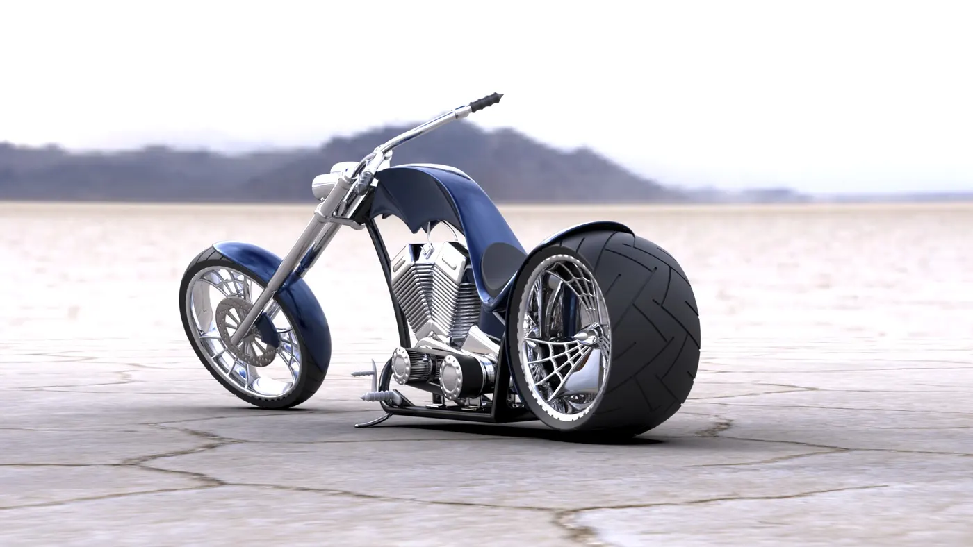
Camera view angle:
Conclusion:
At the end of the project, each component is designed individually in part files and assembled to complete the Chopper Design. Based on this design of model & assembly i have concluded that i have successfully learnt to use surfce and solid modelling features and also learnt to render the model using photoview 360.
Drive Link for the Chopper model and rendered images: https://drive.google.com/drive/folders/1AR7mmQfoE9NHcFl7B3-WXd7BGazLSqPR?usp=sharing