Photo Realistic Rendering of American Chopper
Title :- Photo Realistic Rendering of American Chopper.
Objective :- To design & model each component required to make assembly of American Chopper & finally make a Photorealistic Rendering of the complete assembly of American Chopper.
Introduction :-
The following list is the key parts/models we will be dealing with under solid modeling using SOLIDWORKS.
- 1. Transmission belt, front & rear fender modeling
- 2. Chain, side stand & pedals modeling
- 3. Front & rear wheel modeling
- 4. Engine modeling
- 5. Chassis for American Chopper designing
- 6. Front fork designing
- 7. Oil tank designing
- 8. Creating the assembly of American Chopper
- 9. Performing the rendering on assembly created by using Photoview 360 & SOLIDWORKS Visualise as the rendering tool.
Design Methodology/ Approach:-

Description :-
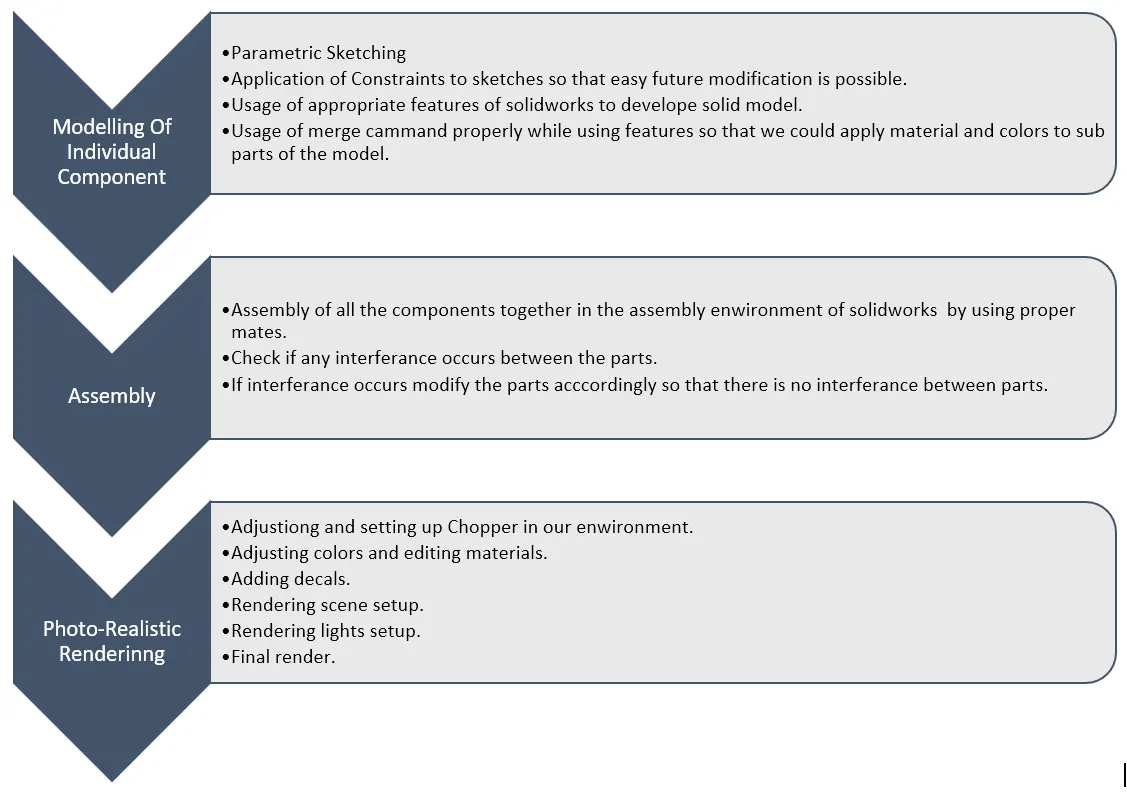
Transmission Belt :- Design & modeling of transmission belt include a simple sketch which includes some constraints. We provided the thickness of 3mm in the sketch itself. The fully defined sketch is then followed by the Extrude Boss/Base feature in the feature tab by which we provided width of 32mm. Finally, we provided the fillet on the edges allover our belt.
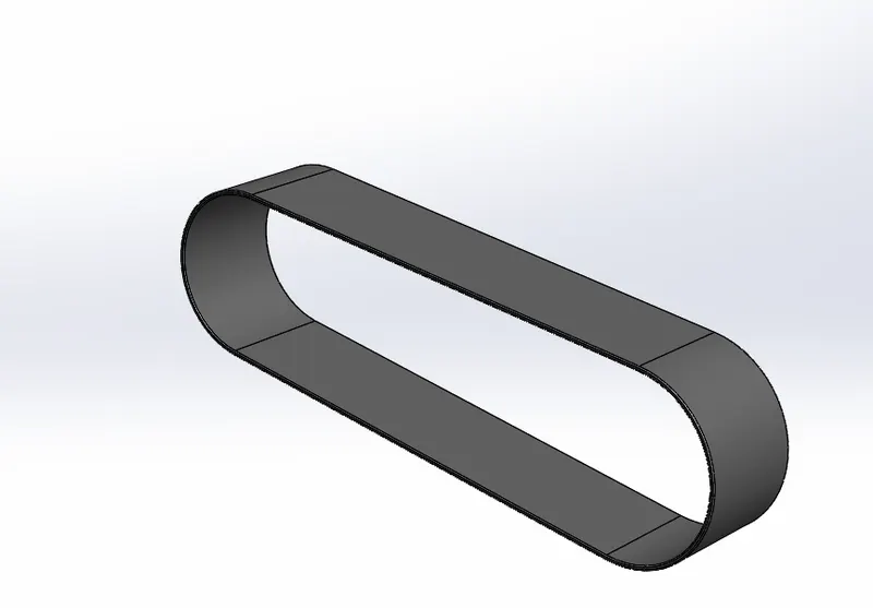
Kickstand :- The design of the kickstand includes a variation of the section from one plane to another plane up to the next section along the guided path. So, we have made an elliptical sketch on a front plane. Then we have made a curve on a midplane passing through the center of an ellipse which we have made on the front plane. The curve will act as a guided curve for the kickstand or we can say the curve for which we need our kickstand to be designed. Afterward, we have added a plane perpendicular to the curve at its endpoint. Then we have added a sketch of an ellipse that is of a smaller size than earlier. Finally, we used the Lofted Boss/Bass feature from the feature tab in which we have added two sections and a guided curve on the midplane to developed a kickstand profile. We also used the split feature to make a flat surface which will act as a rest surface for the kickstand on the ground. In the split feature, we can remove or cut the portion of the model as required by making proper reference as a sketch such as a line. We used a dome at the ends of each section to add an aesthetic look to the stand.
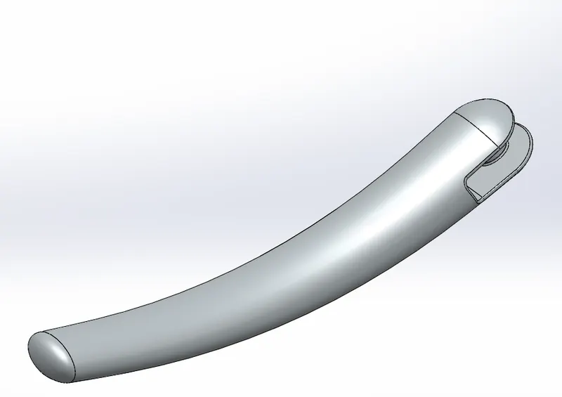
Front and Rear Fender :- As we can observe fender is a circular part having constant cross-section. We have designed front and rear fender in Solidworks by using a revolve feature. Revolve feature requires a sketch or a sketch of a cross-section to be revolved around a selected axis. So we have created a sketch on a vertical plane and created an axis at the origin by using the reference geometry tab. After creating revolve parts as per the required angle we used the split feature to create the aesthetic look at the front and the rear end offender. The split feature includes the creation of a sketch parallel to the surface to be cut and we can select the part to be cut.
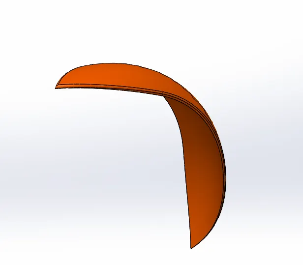
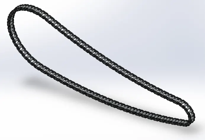
Chain :- The chain of the bike is an assembly of different links and pin together. But we have designed it as a single part. For this, we have used the creating the blocks feature. We have created sketch blocks and then we recall them to create links and pin of the chain by using the extrude boss/base feature. After designing links and a pin we have used a curved driven pattern feature to pattern these links along the desired path and finally, we get the complete chain.
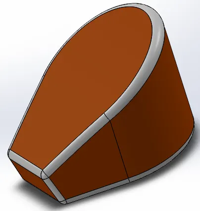
Oil Tank :- For the creation and design of the oil tank, we have used two extrusions perpendicular to reach others. We have created a sketch on each perpendicular plane and used the extrude boss/base tool to concert sketches into split bodies. We then used the Combine tool to create the desired shape of the oil tank.
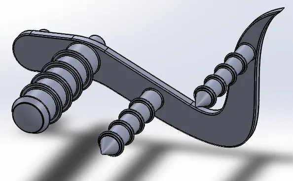
Pedal :- For the design of the pedal, we have created a basic sketch using proper constraints. This sketch is then used for creating different solid extrusions by using the extrude boss/base feature. Then we have used the linear pattern for creating multiple rings over the footrest.
Front and Rear Wheel :-
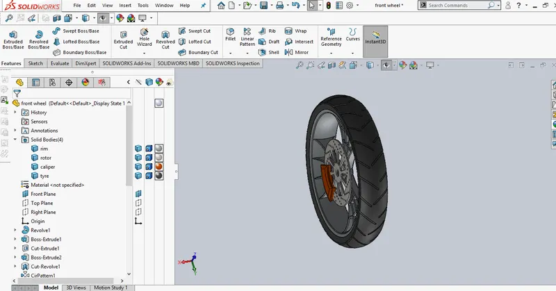
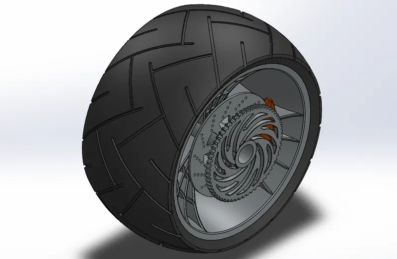
For the design of the front and rear wheel, we have again used a revolve feature which includes creating a sketch as a cross-section. We created a rim's outer part by using a revolve feature and then created an inter part called alloys by creating a sketch and then excluding it. We then used a circular pattern to create 3 numbers of alloys.
After creating a rim we created a brake disc by using extrude boss/base feature but this time we do not use the merge option and created it as a subpart. Similarly, brake caliper has been designed and change is added for a better pathetic look.
Finally, the rubber part or outer part of the wheel is designed by revolving features, and grips are made by using extrude boss/base, and tire grips are made by extruding and patterning.
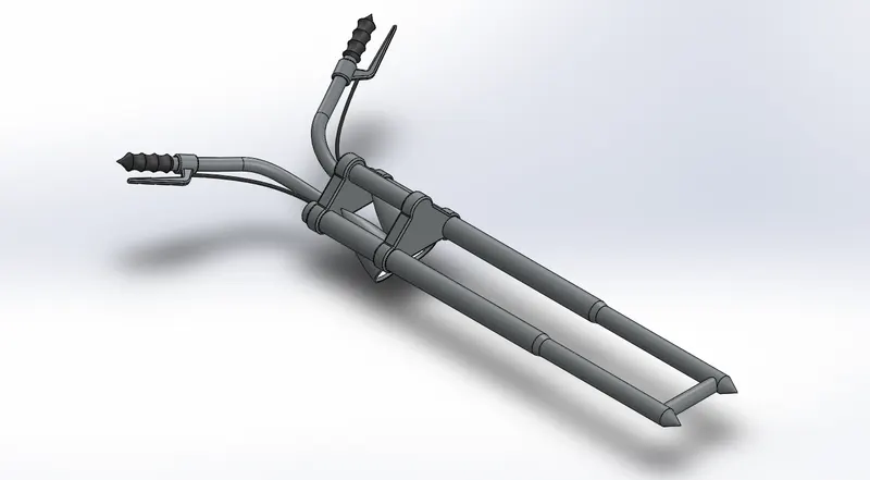
Front Fork :-As we observe front fork, the design is symmetric about mid-portion. We followed the same methodology in design. we have designed half portion first and then mirror it about midface. we use revolve feature to create a lower bar which is a step bar then to create a handle and break wire we used the project curve option. Project Curve feature uses the sketches on perpendicular planes and creates a new 3D curve which is a result of the intersection of two curves on each perpendicular plane. After creating a 3D curve we use swept boss/ base feature to create handle and wire. Finally, we mirrored the part and gets the final part.
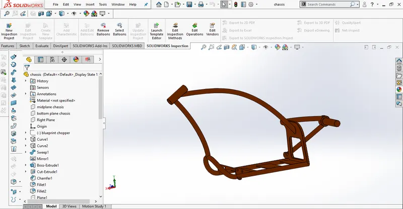
Chassis :- For the design of the chassis, we require some kind of reference regarding its length and some curve parts. So we insert an image in the sketch for reference. We then used the project curve feature to create a 3D curve for the bottom part of the chassis and then we used a swept boss/base feature. By using the covert entities feature we create a sketch by taking reference from the image and by applying the swept feature we created the rear portion of the chassis. Similarly, the front portion of the chassis is created by taking reference from the inserted image.
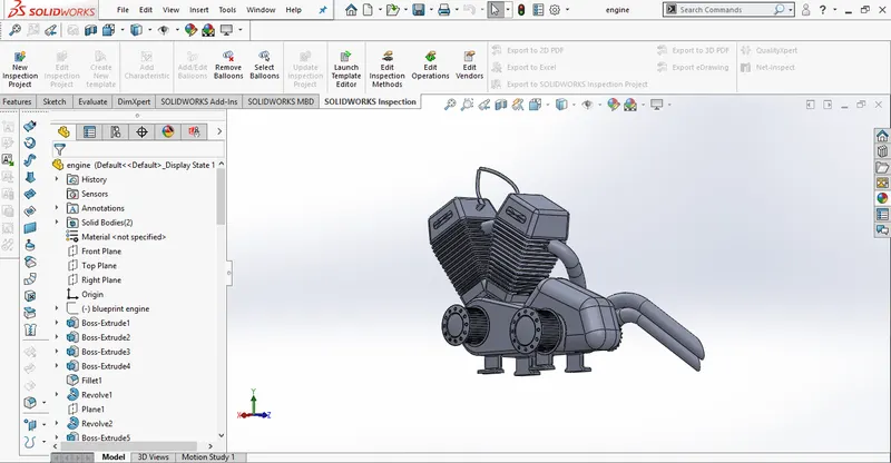
Engine :- As we did earlier we followed the same methodology. we insert an image in the sketch for reference. By taking reference from the image and using the Extrude boss/base feature we created a gearbox and combustion chamber. We then created fins on the combustion chamber bu using the extrude cut and linear pattern features. Finally, by using the project curve feature we created 3D curves for exhausts and uses swept features to create a solid body for exhaust.
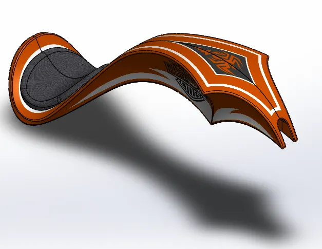
Gas Tank :- As we can see, gas tank involves lot of curved surfaces. So we tried to design it by using surface tools. We first inserted an image for reference. By taking reference we created a top surface of the tank by using a swept surface tool. The swept surface tool uses two sketches on perpendicular to each other. one will then act as a width of the surface while the other one guides the surface along the length. As per the requirement of the shape of the tank, we then trim this surface by using the trim surface tool. Creating the other surfaces we first created curves by using the Project curve feature. We then use the boundary surface tool to create surface enclosed by these curves. similarly, we used surface loft command to create more surfaces. We used a split line tool to create an extrusion over the top surface to creat seat. We also used a knit surface tool to convert the surface body into solid and finally, we used shell feature to create a hollow tank with considerable thickness.
Assembly of the American Chopper :-
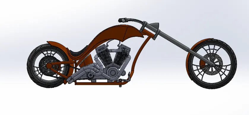
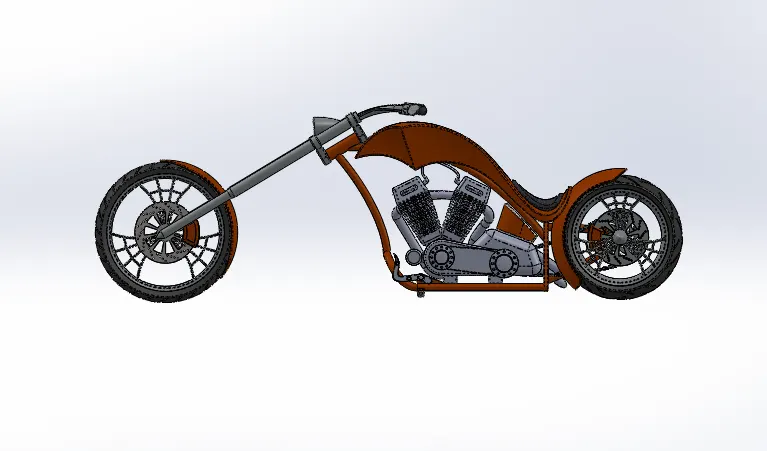
1. A new assembly was created in the Solidworks and the first component to be imported was the chassis.
2. The next component inserted into the assembly was the engine.
3. The next component inserted into the assembly was the pedal. Three mates were applied to the part
4. Next, a mirrored component of the pedal was created for the other side of the bike.
5. The next component inserted into the assembly was the kickstand. Three mates were applied to it. The limit angle mate available under the advanced mate options was used to permit the rotation of the kickstand.
6. The next part added to the assembly was the transmission belt. Width, concentric, and angle mates were applied to position it properly in the assembly.
7. The next part added to the assembly was the oil tank.
8. Next component added to the assembly was the rear fender.
9. The next component added to the assembly was the rear fender.
10. After that the chain was added to the assembly. The mates applied to position the chain properly.
11. The next component inserted into the assembly was the fuel tank.
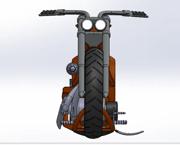
12. After that front fork was added to the assembly.
13. The next part added to the assembly was the front wheel. A plane in the middle of the front fork was created to mate the front wheel properly.
14. The final component inserted into the assembly was the front fender
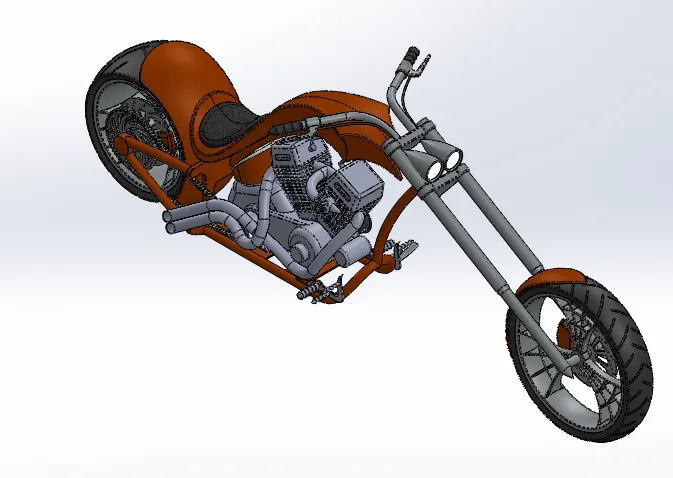
Rendering of American Chopper :-
Rendering is process of creating realistic images of the model with environment.
In rendering various aspects such as camera, light, environment, background scene, appearance, etc. are taken in consideration before final rendering. To check the all thing preview rendering option is used.
There are two ways of rendering in SOLIDWORKS.
- Photoview 360
- Solidworks Visualize
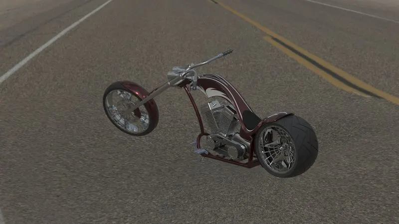
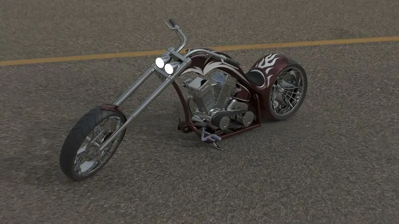
Conclusion:- At the end of the project, each component is designed individually in part files and assembled to complete the Chopper Design. And to set up an additional appearance like Decals, Cameras, Lights, etc to make it more Photo Realistic.