Photo Realistic Rendering
MODELLING AND RENDERING OF AN AMERICAN CHOPPER
OBJECTIVE:
The main objective of this project report is,
- To create/model of an American Chopper by using 2D sketch tools and 3D features through the designing software SOlidworks, which was published by Dassault systems.
- To make an Assembly with individual parts with proper mates and relations.
- To make a photo realistic rendering with Photoview 360 and Solidworks visualize.
INTRODUCTION:
About Solidworks:
- SolidWorks released its first product SolidWorks 95 in November 1995. Solidworks was developed by Jon Hirsch tick – an MIT graduate and was bought by Dassault Systems into the market in 1997. The software now consists of a number of programs that can be used for both 2D and 3D Designs.
- SOLIDWORKS is an industry-leading CAD (Computer-Aided Design) and CAE (Computer-Aided Engineering) software used by millions of engineers across the world. It was published by Dassault Systems
- SolidWorks files (previous to version 2015) use the Microsoft structered storage file format. This means that there are various files embedded within each SLDDRW (drawing files), SLDPRT (part files), SLDASM (assembly files) file, including preview bitmaps and metadata sub-files. Various third-party tools can be used to extract these sub-files, although the sub-files in many cases use proprietary binary file formats.
- SolidWorks allows saving 3D model information in *.step format, which lets the model be displayed and modified in other platforms from other vendors. It’s one of the most popular design and engineering software on the market. Known for its range of features and high functionality, SOLIDWORKS is used across multiple professions and industries around the world.
About American Chopper:
- The term “chopper” came from motorcycle owners “chopping” every non-essential part they could off their motorcycles to make them as light and fast as possible, often with little to no regard for safety.
-
A chopper is a type of motorcycle custom which emerged in the US state of California in the late 1950s. A chopper employs radically modified steering angles and lengthened forks for a stretched-out appearance. They can be built from an original motorcycle which is modified ("chopped") or built from scratch. Some of the characteristic features of choppers are long front ends with extended forks often coupled with an increased rake angle, hardtail frames (frames without rear suspension), very tall "ape hanger" or very short "drag" handlebars, lengthened or stretched frames, and larger than stock front wheels. The "brassy", a set of tubes that connect the rear fender with the frame, and which are often extended several feet high, is a signature feature on many choppers.
-
The first choppers were built in America, and were an outgrowth of the milder customization trend that had originated after WW2 when returning soldiers and others began modifying cars and motorcycles, frequently to improve performance in top-speed races on dry lake beds in Southern California and similar desolate spaces such as unused airstrips in other parts of the country, or on the street for street racing. These early modified motorcycles were known as "bobbers", and there are many common features between bobbers and choppers, with choppers differentiated by more radical modifications, especially frame tube and geometry modifications ("chopped" by welding) intended to make the bike longer.
DESIGN METHODOLOGY:
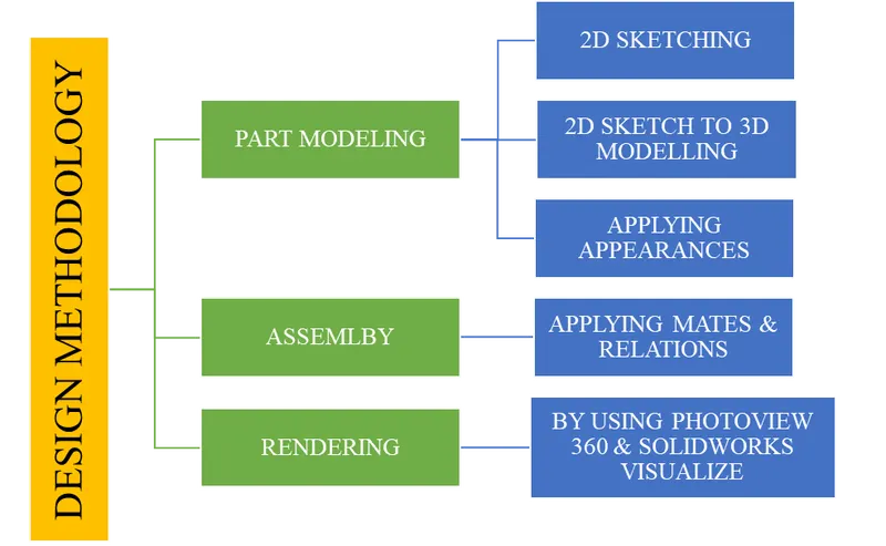
PART MODELLING:
Modelling in generally means to create a virtual prototype of an item. It can be used for various purposes. Consider an engine of car. It has hundreds of parts. Each part can be modelled separately and them can be assembled together to get the engine’s final form. This type of modelling is called Part Modelling.
The following parts are modelled for make an American Chopper.
- Transmission Belt
- Kick Stand
- Front Fender
- Rear Fender
- Chain
- Oil Tank
- Pedal
- Front Wheel
- Rear Wheel
- Front Fork
- Chassis
- Engine
- Gas Tank
DESCRIPTION OF FEATURES:
- 2D SKETCH:
A 2D drawing view consists of two-dimensional elements. It is not associative to a 3D model. A 2D drawing view allows you to quickly create or modify a drawing view without making changes to a part or assembly document.
A sketch is almost always the first step in designing a new part. To begin, create a new part and select your desired template. Once the user interface is visible, click the Sketch tab of the Command Manager and select the Sketch icon on the left-hand side.
In 2D Sketch various tools available like, line, Circle, Ellipse, Rectangle, Arc, Fillet, Spline, Chamfer, etc.
- SKTECH RELATIONS:
Sketch relations help to define a sketch entity by relating them or constraining them to other sketch entities. Sketch relations can either be added or assumed by SolidWorks through built in features (the polygon tool). Note: All relations can be seen and edited by using the display/delete relation icon.
- EXTRUDED BOSS/BASE:
Extrude tool is used to extend a sketched profile in one or two directions as either a thin feature or a solid feature. An extrude operation can either add material to a part (in a base or boss) or remove material from a part.
- REVOLVED BOSS/BASE:
Revolved Boss or Base is a SolidWorks feature tool which is used to create solid 3D model around an axis. We can revolve the sketch around an axis to add materials to it.
- LOFTED BOSS/BASE:
Lofted boss or base tool helps to add materials between two planes as per the sketch profile. The flow of material between sketch profiles in two different planes entirely depends on the sketch shape. You can make adjustemnst using the loft property manager.
- SWEPT BOSS/BASE: Sweep is an extrusion tool that allows you to extrude a profile such as a circle or a square or a complex shape along a sketched path.
- DOME:
Faces to dome. Select one or more planar or non-planar faces. You can apply domes to faces whose centroid lies outside the face. This allows you to apply domes to irregularly shaped contours.
- CUT-EXTRUDE:
Extruded cut feature removes material from the part. The End Condition, Draft, and Thin Feature options are same as described in Extruded Boss/Base.
- REVOLVED CUT: Use the Revolve tool to remove material by revolving a sketched section around a centreline. • To create a cut, use the same angle options as for protrusions.
- SPLIT: Use the Split feature to create multiple parts from an existing part. You can create separate part files, and form an assembly from the new parts. You can split one or more solid or surface bodies. To split a surface, the Trimming Surface must extend past the boundaries of the surface to split.
- FILLET: Fillet/Round creates a rounded internal or external face on the part. You can fillet all edges of a face, selected sets of faces, selected edges, or edge loops.
- CHAMFER: The chamfer tool creates a bevelled feature on selected edges, faces, or a vertex.
- LINEAR PATTERN: Linear pattern features tool is a placed features tool which is used to create patterns of features in linear manner. For linear patterning, there is parent part (Base pattern) which used to create the array of patterns in one or two dimensions. The pattern should follow the exact shape of the main pattern.
- CIRCULAR PATTERN: Use circular patterns to create multiple instances of one or more features that you can space uniformly around an axis. Pattern instances inherit the feature colour of the original feature when the: Pattern is based on one feature.
- CURVE DRIVEN PATTERN: The Curve Driven Pattern tool allows you to create patterns along a planar or 3D curve.
To define the pattern, you can use any sketch segment, or the edge of a face (solid or surface), that lies along the plane. You can base your pattern on an open curve, or on a closed curve, such as a circle.
- MIRROR: The ability to mirror can be found in part and assembly files, and allows you to mirror sketch entities, features, faces, bodies, and components. Mirroring Sketch Entities.
- DYNAMIC MIRROR: The Dynamic Mirror Entity tool allows a user to mirror a sketch about a line while the user is creating their sketch.
- COMBINE: The Combine feature in SOLIDWORKS is a great tool used most often in surface modelling as it allows you to take molds of created parts for mold operations. It is also useful when creating negative spaces for a part to fit into to show where an item might reside in an assembly
- SHELL: The shell tool hollows out a part, leaves open the faces you select, and creates thin-walled features on the remaining faces. If you do not select any face on the model, you can shell a solid part, creating a closed, hollow model. You can also shell a model using multiple thicknesses
- SKETCH BLOCK: You can make, save, edit, and insert blocks for drawing items and sketch entities that you use often, such as standard notes, title blocks, label positions, and so on. You can attach blocks to geometry or to drawing views, and you can insert them into sheet formats.
- PROJECT CURVE: Project curves are used to create a smooth curve between two points in a 3D space. They can be used for a variety of purposes, such as creating a swept surface or blending two surfaces together. It plays an important role in SOLIDWORKS design projects.
- COMPOSITE CURVE: The Composite Curve feature allows users to combine edges of parts, surfaces, sketch curves or 3D curves into a single curve. This saves time by reducing the number of picks and clicks for downstream features.
- PLANES: The most common type of reference plane is an offset plane. To create an offset plane, select the Reference Geometry drop down on the Command Manager and choose the Plane option. Once the option to create a plane is open, select a face or another plane and set a distance for the offset
- LOFTED SURFACE: Loft Surfaces are surfaces generated by multiple 3D Curves or existing edges creating a smooth tangency between the selected curves.
- SWEEP SURFACE: Sweep surfaces are surfaces that are generated from a section curve positioned along a path.
- FILLED SURFACE: The Filled Surface feature constructs a surface patch with any number of sides, within a boundary defined by existing model edges, sketches, or curves, including composite curves.
- SURFACE TRIM: Primarily used to cut away material from a surface, and provides two modes: Standard and Mutual.
- SURFACE KNIT: Surface knit is used to knit the two free edges/open edges of the surfaces together. Also, it reduces the gap between the two edges of the surface.
- BOUNDARY SURFACE: The boundary surface feature lets you create surfaces that can be tangent or curvature continuous in both directions (all sides of the surface). In most cases, this delivers a higher quality result than the loft tool.
- TRANSMISSION BELT: Belts are mechanical elements used for power transmission without phase shift. They are loops of flexible materials used to mechanically connect several rotating shafts, most often parallel. Belts can be used as a transmission element, to efficiently transmit power or movement.

FEATURES USED:
- 2D Sketch
- Extrude Boss
- Fillet
2. KICK STAND: A kickstand is a device on a bicycle or motorcycle that allows the bike to be kept upright without leaning against another object or the aid of a person. A kickstand is usually a piece of metal that flips down from the frame and makes contact with the ground.
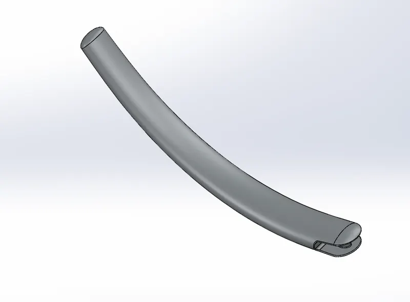
FEATURES USED:
- 2D Sketch
- Spline
- Lofted Boss
- Dome
- Extrude Cut
- Split
- Fillet
3 & 4. FRONT FENDER & REAR FENDER: Fender is the American English term for the part of an automobile, motorcycle or other vehicle body that frames a wheel well (the fender underside). Its primary purpose is to prevent sand, mud, rocks, liquids, and other road spray from being thrown into the air by the rotating tire.
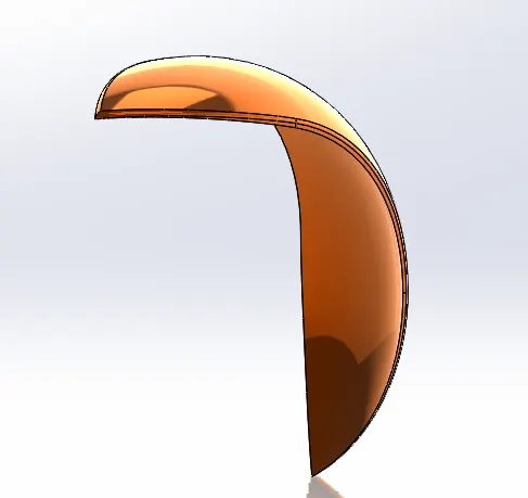
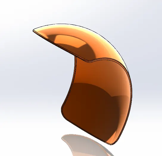
3. FRONT FENDER 4. REAR FENDER
FEATURES USED:
- 2D Sketch
- Spline
- Revolved Boss
- Split
- Fillet
5. CHAIN: The chain transmits mechanical power to the bike via the turning of a sprocket gear, the teeth of which mesh with the links in the chain to pull it into action. This is in contrast to the belt drive and the shaft drive, both of which require less maintenance but are much costlier to produce than the chain drive.
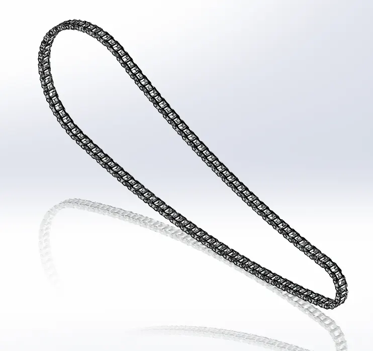
FEATURES USED:
- 2D Sketch
- Sketch Blocks
- Extrude Boss
- Fillet
- Curve Driven Pattern
- Mirror
6. OIL TANK: The main engine cylinder oil is used inside the combustion chamber between the piston and the liner, and is stored in the cylinder oil tank. The bulk oil is bunkered directly into these tanks. The low sulphur oil is kept separate in different tanks.
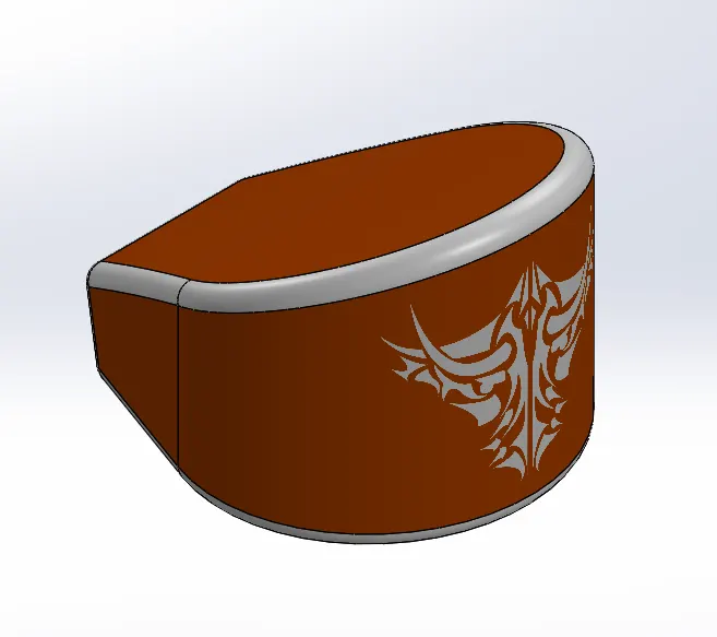
FEATURES USED:
- 2D Sketch
- Spline
- Extrude Boss
- Combine
- Fillet
- Shell
7. PEDAL: There are three main types of pedals, Flat Pedals, Mountain Bike Clipless, and Road Clipless. There are many arguments as to which is better. However, it depends on your riding and the bike you are using. Let's go through each pedal style so you can decide which will suit you.
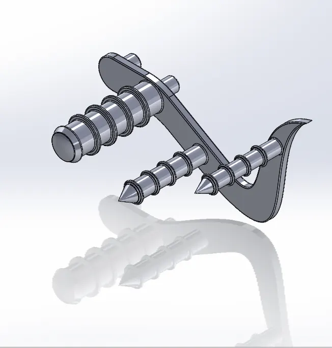
FEATURES USED:
- 2D Sketch
- Spline
- Extrude Boss
- Fillet
- Revolved Boss
- Chamfer
- Linear Pattern
8. FRONT WHEEL: A wheel is a circular block of a hard and durable material with a circular hole through an axle bearing around which the wheel rotates, where the middle has been drilled.
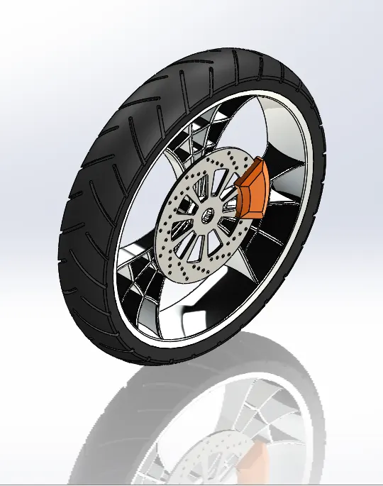
FEATURES USED:
- 2D Sketch
- Revolved Boss
- Extrude Cut
- Circular Pattern
- Fillet & Chamfer
9. REAR WHEEL: A wheel is a circular block of a hard and durable material with a circular hole through an axle bearing around which the wheel rotates, where the middle has been drilled.
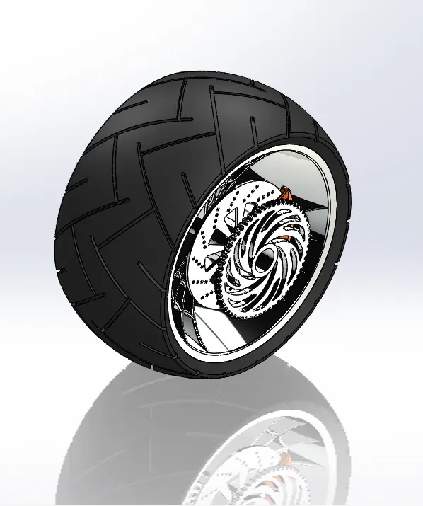
FEATURES USED:
- 2D Sketch
- Revolved Boss
- Extrude Cut
- Circular Pattern
- Fillet & Chamfer
10. FRONT FORK:
In nearly every motorcycle available today, the front wheel is held on by an axle that's connected to the fork. It's called a fork because it has two prongs that go around each side of the wheel.
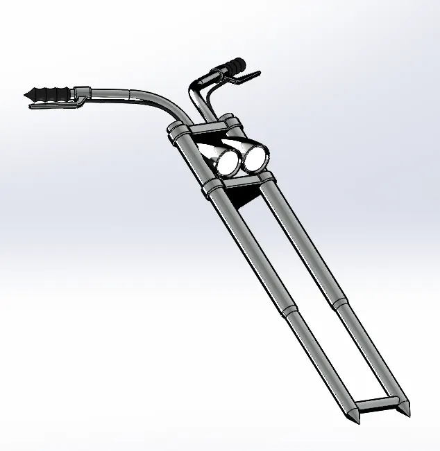
FEATURES USED:
- 2D Sketch
- Spline
- Revolved Boss
- Extrude Boss
- Extrude Cut
- FIllet
- Dome
- Revolved Cut
- Sweep Boss
- Body Move/Copy
- Curve
- Mirror
- Combine
- Plane
11. CHASSIS: A motorcycle's chassis or frame forms its skeleton. All the components of a motorcycle, like the suspension, wheels, fuel tank, seats, handlebars etc, are attached to this base structure which lends a motorcycle its strength and ability to handle well.
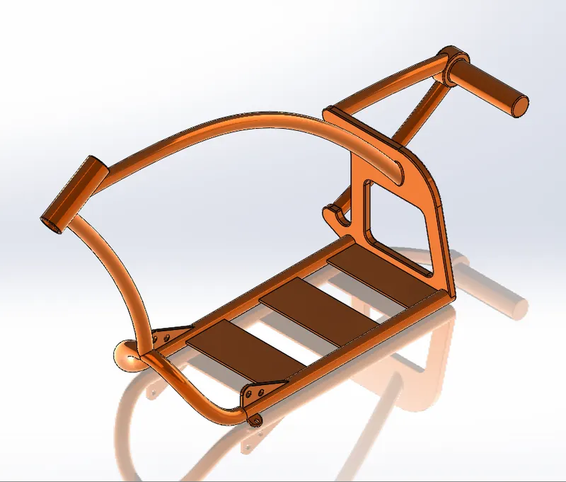
FEATURES USED:
- BluePrint Chopper
- 2D sketch
- SPline
- Projected Curve
- Swept Boss
- Extrude Boss
- Extrude Cut
- Chamfer
- FIllet
- Plane
- Dome
- Split
- Combine
- Revolved Boss
- Mirror
12. ENGINE: A motorcycle engine is an engine that powers a motorcycle. Motorcycle engines are typically two-stroke or four-stroke internal combustion engines, but other engine types, such as Wankels and electric motors, have been used.
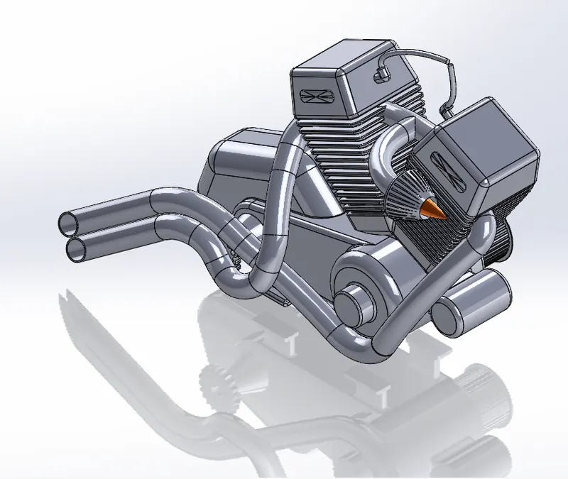
FEATURES USED:
- BluePrint Sketch
- 2D sketch
- Spline
- Extruded Boss
- Fillet
- Revolved Boss
- Circular Pattern
- Dome
- Extrude Cut
- Chamfer
- Fillet
- Linear Pattern
- Mirror
- Plane
- Swept Boss
- Project Curve
- Composite Curve
- Split
13. GAS TANK: A fuel tank (also called a petrol tank or gas tank) is a safe container for flammable fluids. Though any storage tank for fuel may be so called, the term is typically applied to part of an engine system in which the fuel is stored and propelled (fuel pump) or released (pressurized gas) into an engine.

FEATURES USED:
- Surface Sweep
- Surface Trim
- Plane
- Project Curve
- Surface Loft
- Boundary Surface
- Mirror
- Surface KnitSplit Line
- Surface Extrude
- Fillet
- Sweep cut
- Spline
ASSEMBLY IN SOLIDWORKS:
An assembly is a document in which parts, features, and other assemblies (subassemblies) are mated together. The parts and subassemblies exist in documents separate from the assembly.
The following mates are used in American Chopper Assembly.
- Coincident Mate
- Concentric Mate
- Limit Angle
- Limit Distance
- Width Mate
- Parallel Mate
- Position Mate
- Tangent Mate
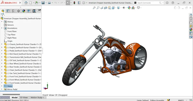
FRONT VIEW OF CHOPPER:
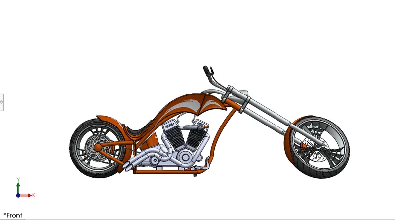
SIDE VIEW OF CHOPPER:
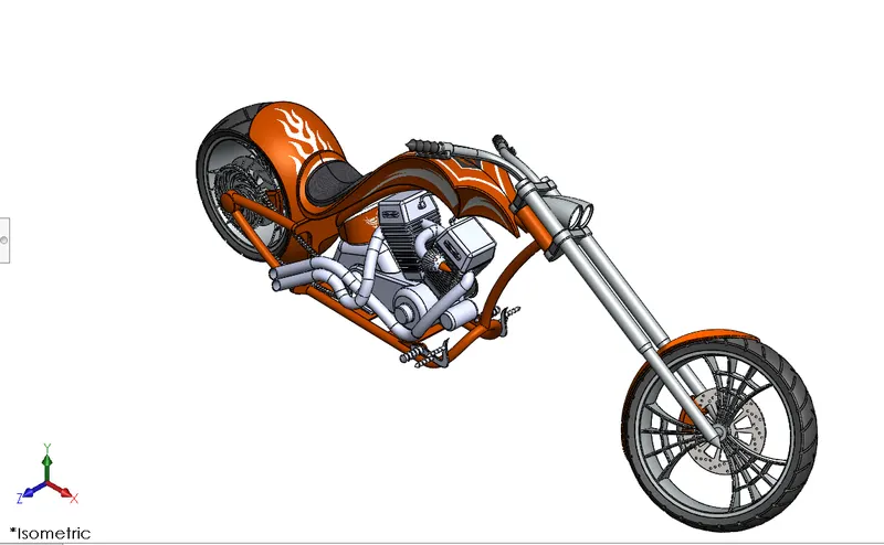
ISOMETRIC VIEW OF CHOPPER:
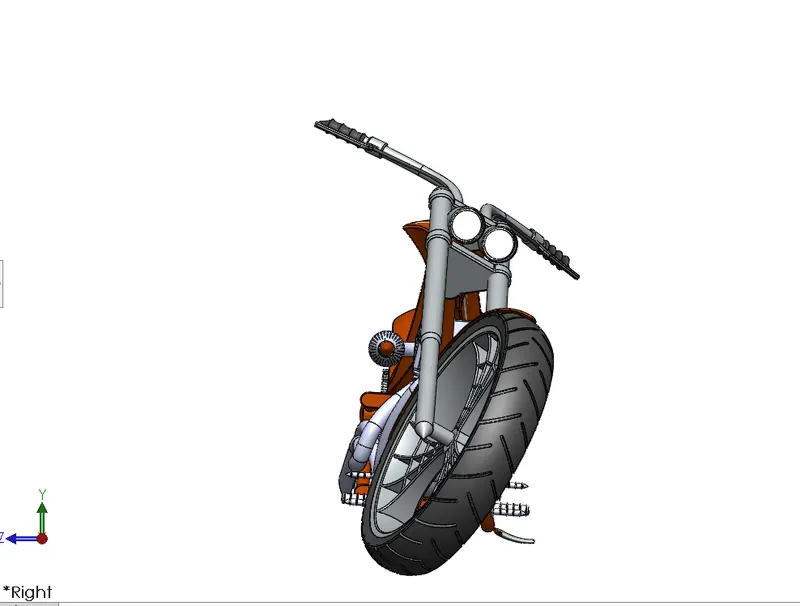
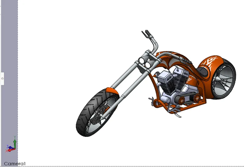
CAMERA VIEW OF CHOPPER:
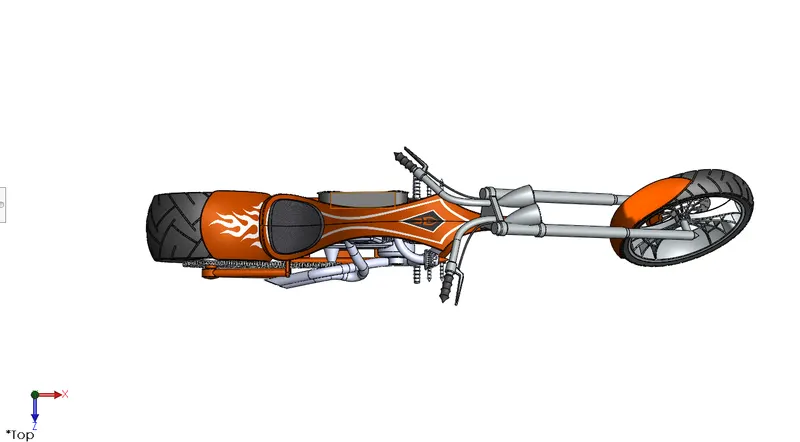
TOP VIEW OF CHOPPER:
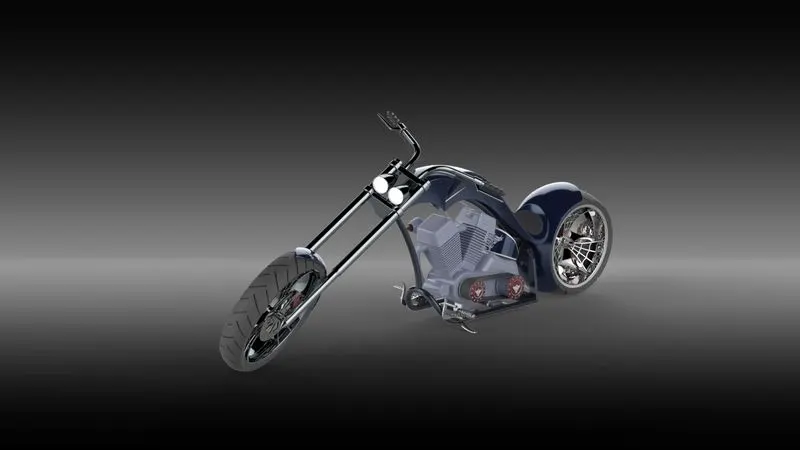
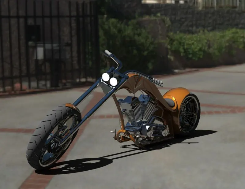
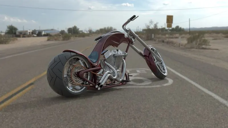
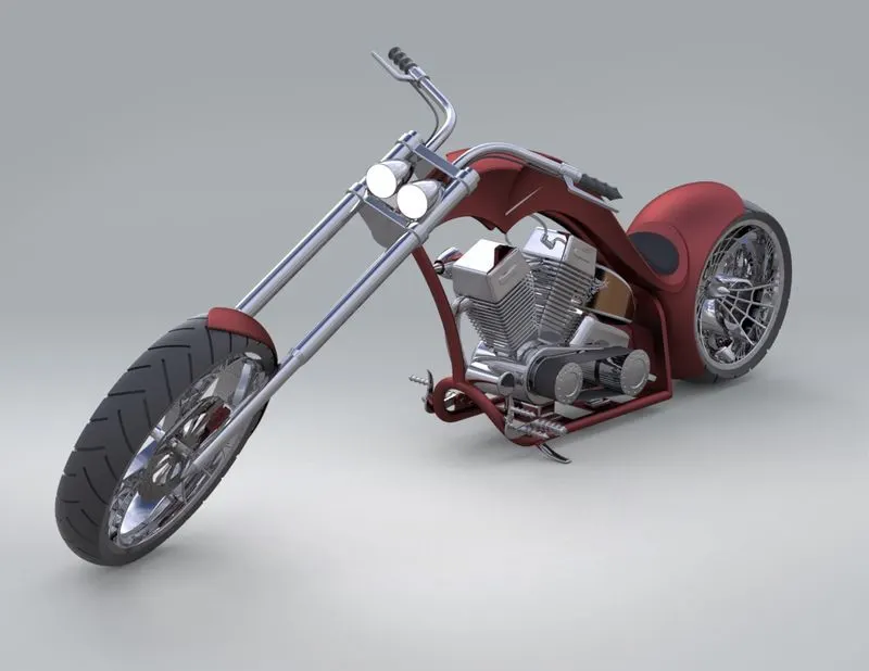
RENDERING OF AMERICAN CHOPPER:
Rendering is the process of creating realistic images of the Photorealistic model with the environment. Rendering has been done in two ways on Solidworks.
- PhotoView 360
- Solidworks Visualize
By use of this feature, we can transform our model into a realistic object to create the illusion of how our actual object will look like and it helps us to get more clear idea about the concept of our new product and its appearance.
SOLIDWORKS Visualize provides industry-leading rendering capabilities with visual design-oriented features and workflows in place. This allows for fast and easy creations of visual content that communicates a designer's vision and showcases your part in the most stunning way.
CONCLUSION:
- Finally American Chopper was done successfully with individual parts in solidworks.
- Learnt, how to make sketch fully define and usage of different features for modelling different parts.
- Rendering done for chopper with different environments with different appearences through Solidworks.