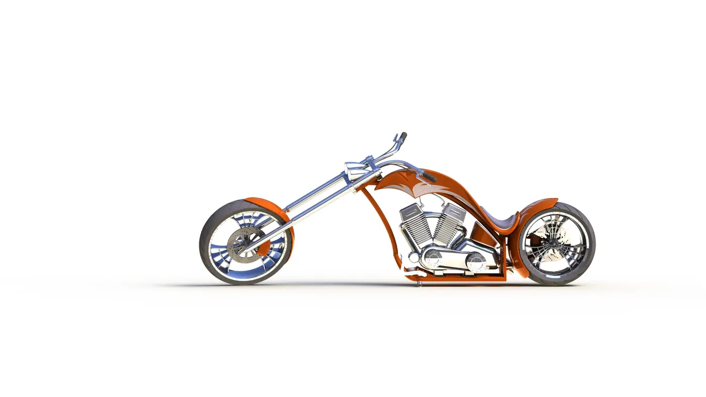
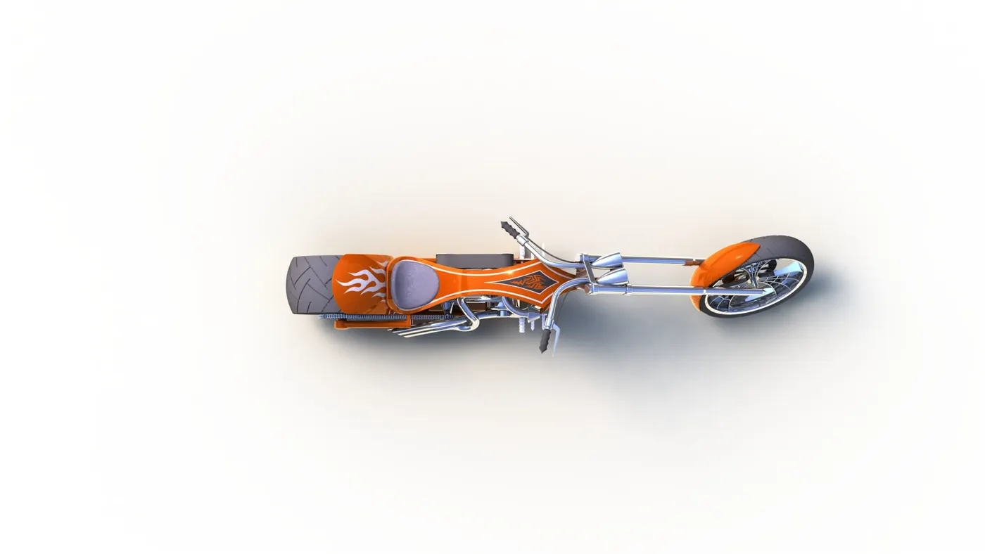
Photo Realistic Rendering
Design of American Chopper Using SolidWorks
OBJECTIVE:
The objectives of this report are:
1.To learn the tools and its features present in solid-works software
- To create a part modelling of each and every components of American Chopper
3.To assemble the part modelling of components to form entire American chopper assembly.
INTRODUCTION:
Part Modelling:
It is nothing but to create virtual prototype of model. In this report modelling of every part of American chopper is created and then assembly is also done.
METHODOLOGY:
The parts of American Chopper that are modelled and assembled are,
1.Transmission Belt
2.Kickstand
3.Front Fender
4.Rear Fender
5.Chain
6.Oil Tank
7.Pedal
8.Front Wheel
9.Rear Wheel
10.Front Fork
11.Chassis
12.Engine
13.gas Tank
PARTS AND FEATURES DESCRIPTION:
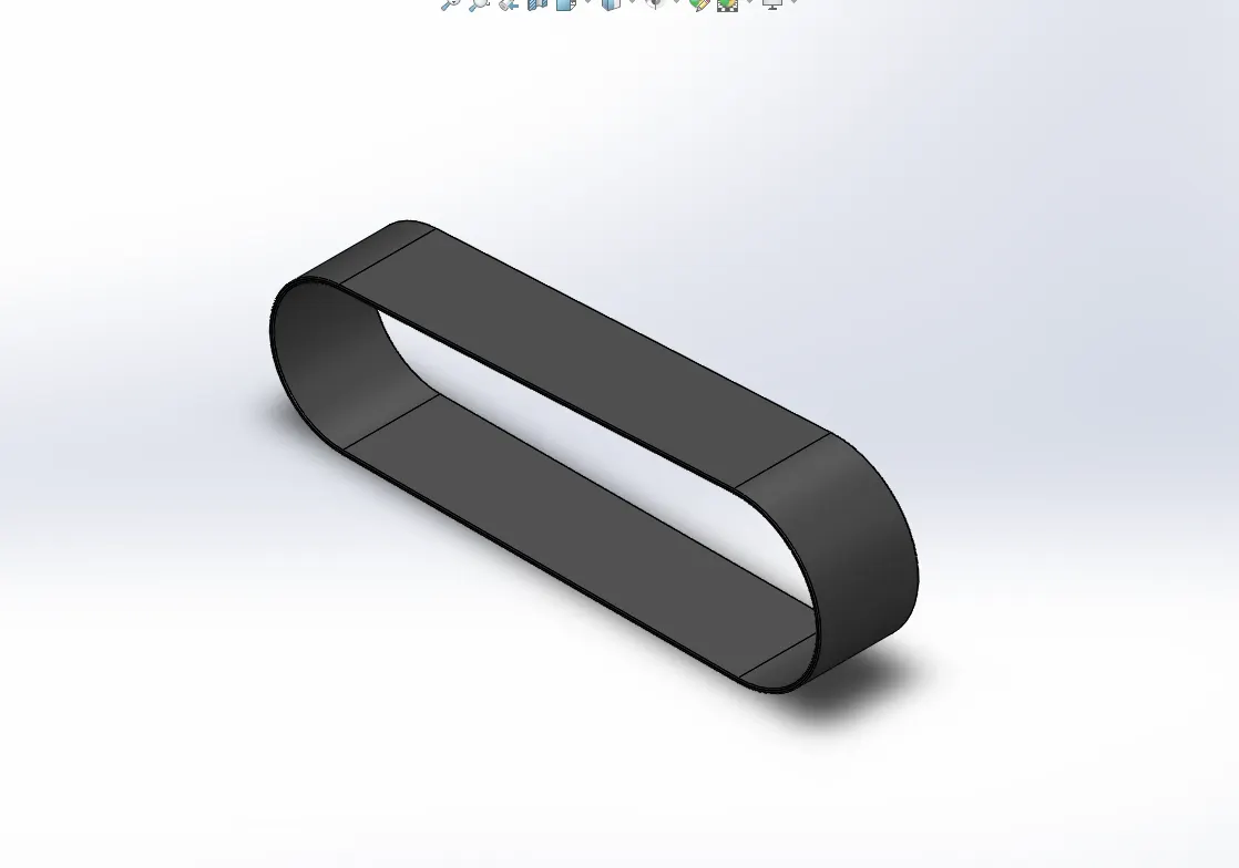
1.Transmission Belt:
It is loop of flexible material used to link two or more rotating shafts mechanically as parallel.
Features Used:
1.Sketch
2.Boss Extrude
3.Fillet
Description:
Sketch:
It is the basis for 3d model can create sketch on default planes or created planes.
Boss Extrude:
It helps to add thickness on 2D sketch in third dimension.
Fillet:
It creates a rounded internal or external face on the part. It must be applicable only on edges.
2.Kickstand:
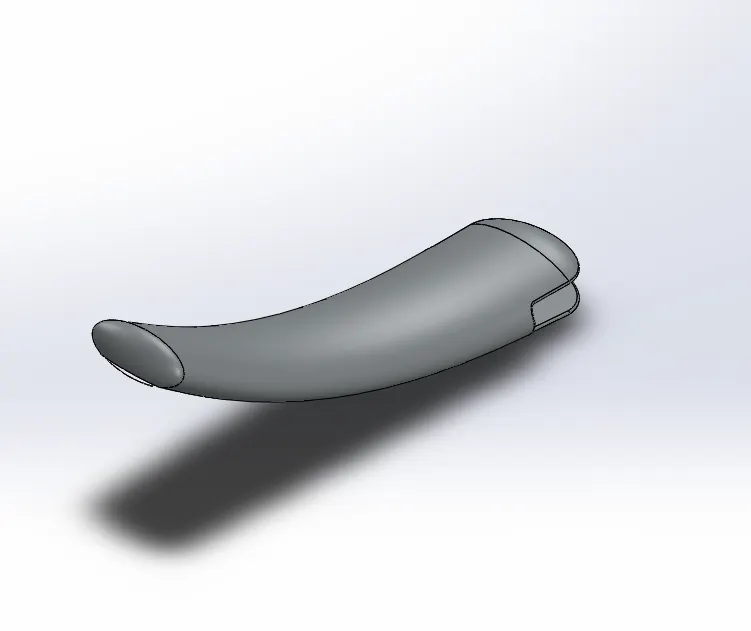
It allows American Chopper to be kept upright without leaning against another object .It is a piece of metal that flips down from the frame and makes contact with ground.
Features Used:
1.sketch
2.Loft
3.Dome
4.Cut Extrude
5.Split
6.Boss Extrude
7.Fillet
Description:
Loft:
It creates a feature by making transitions between profiles. It must be created using two or more profiles.
Dome:
It is used to create bump on selected top face.
Cut Extrude:
It cuts a solid model by extruding a sketched profile in one or two directions.
Split:
It is used to split the face, sketch, and surface on multiple bodies.
3.Front Fender:
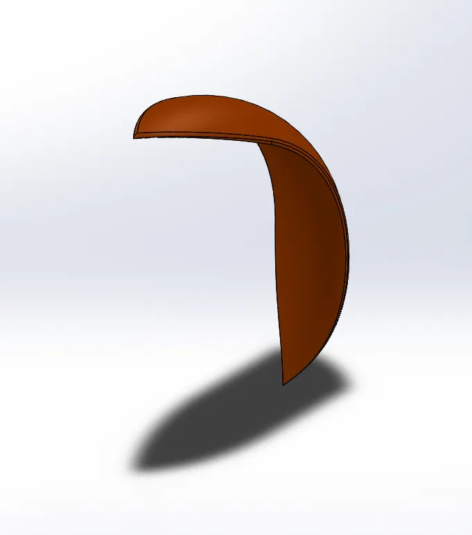
It is part that frames front wheel well (fender underside). The major role of fender is to cover the tire to avoid sand, rocks, spray particles, etc.. which are thrown while in driving stage.
Features Used:
1.sketch
2.Revolve
3.Split
4.Fillet
Description:
Revolve:
It revolves a selected sketch contours around an axis to create a solid feature.
4.Rear Fender:
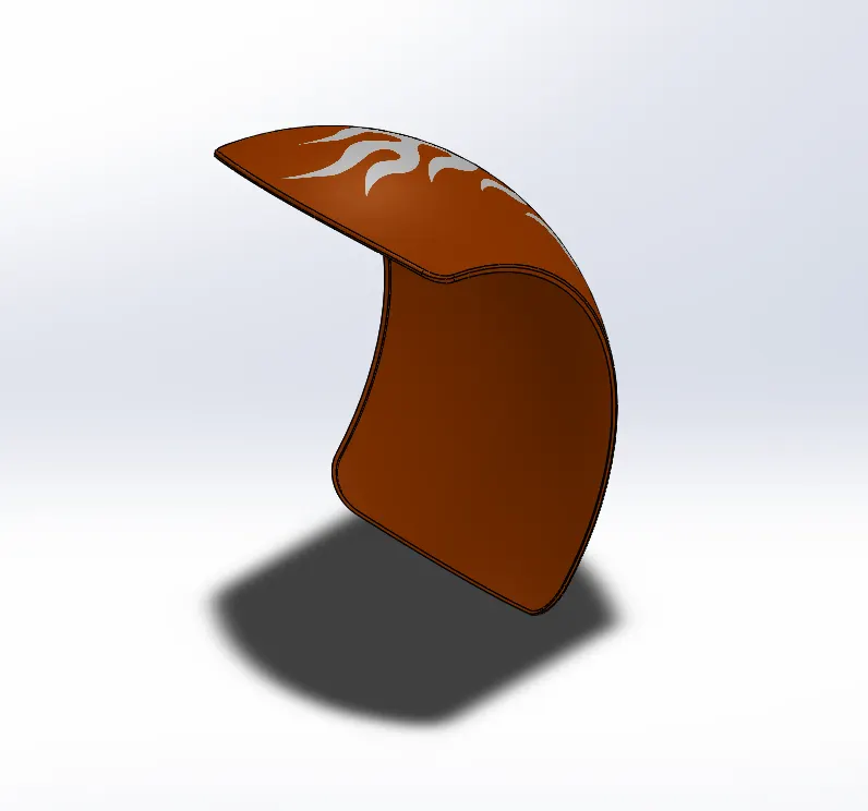
It is part that frames rear wheel well (fender underside). The major role of fender is to cover the tire to avoid sand, rocks, spray particles, etc.. which are thrown while in driving stage.
Features Used:
1.sketch
2.Revolve
3.Split
4.Fillet
5.Shell
Description:
Shell:
It hollows out a part, leaving open the faces you select, and creating thin-walled features on the remaining faces.
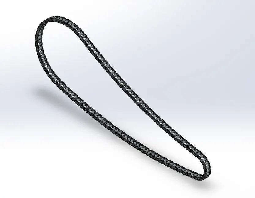
5.Chain:
Chain is type of transmission system that is used to transmit a power from the engine to rear wheel.
Features Used:
1.Sketch
2.Boss Extrude
3.Fillet
4.Circular Pattern
5.Mirror
Description:
Circular Pattern:
It patterns or creates no of instances of features, faces and bodies around axis.
Mirror:
It creates copy of features, faces and bodies about plane or planar face.
6.Oil Tank:
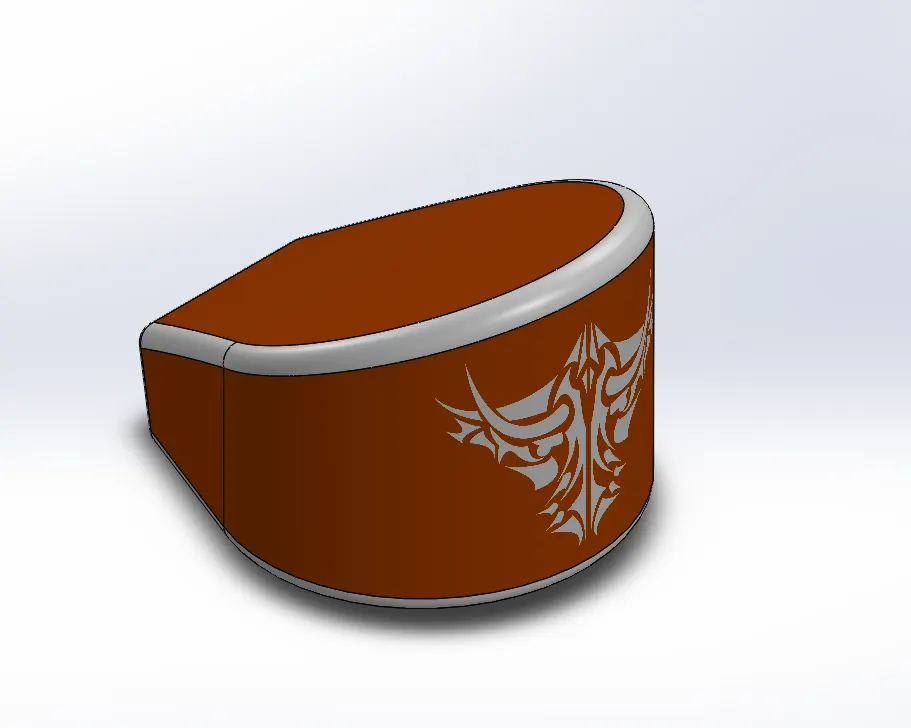
The purpose of oil tank is to store oil (lubricant) to lubricate engine parts to avoid friction due to overheat.
Features Used:
1.Sketch
2.Boss Extrude
3.Combine
4.Fillet
5.Shell
Description:
Combine:
It is used to combine two or more solid bodies.
7.Pedal:
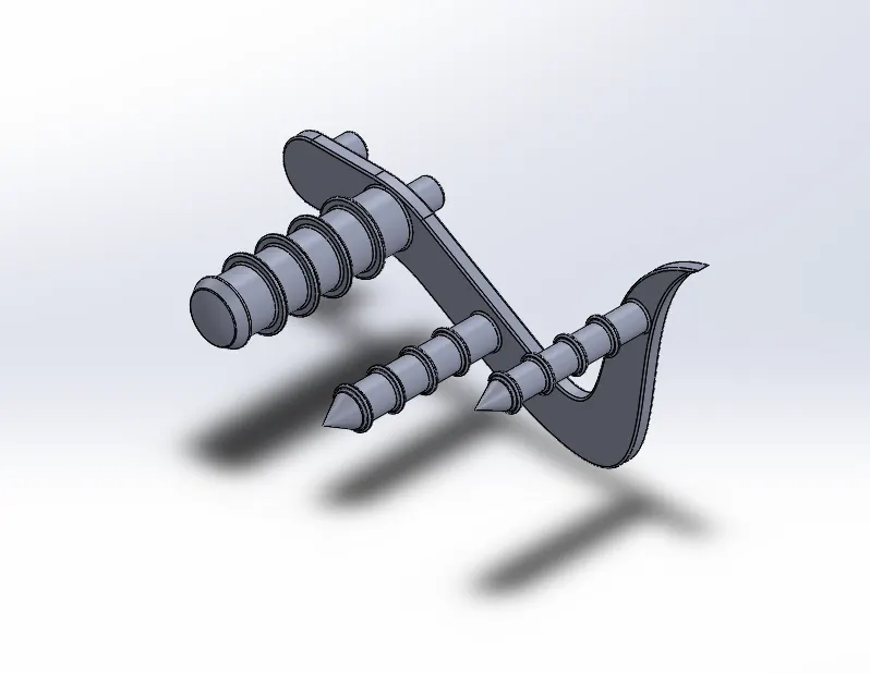
It is the part where the foot of the rider rests and place where the gears and brakes are available easily to rider.
Features Used:
1.Sketch
2.Boss Extrude
3.Fillet
4.Revolve
5.Dome
6.Chamfer
7.Linear Pattern
Description:
Chamfer:
It creates a bevel feature along edge, a chain of tangent edge or vertex.
Linear Pattern:
It patterns or creates no of instances of features, faces and bodies in one or two linear direction.
8.Front Wheel:
It is the rolling part connected to front fork. It totally depends upon front fork where in turning of vehicle front wheel turns along with front fork to guide the vehicle to same direction.
Features Used:
1.Sketch
2.Revolve
3.Boss Extrude
4.Cut Extrude
5.Cut Revolve
6.Circular Pattern
7.Combine
8.Fillet
9.Chamfer
Description:
Cut Revolve:
It cuts a solid model by revolving a sketched profile around an axis.
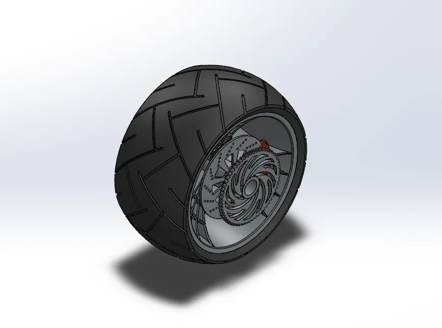
9.Rear Wheel:
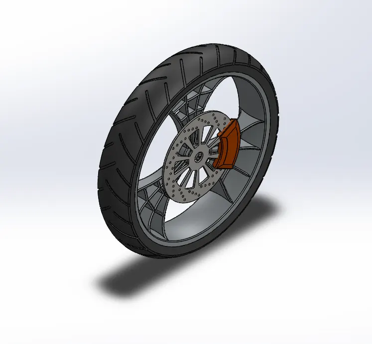
It is a rolling part connected to chassis. It receives power from engine through chain drive to make vehicle to move. Generally rear wheel leads the vehicle to move from one place to another.Rim, tyre, rotor,sprocket,and caliper are parts of rear wheel.
Features Used:
1.Sketch
2.Revolve
3.Boss Extrude
4.Cut Extrude
5.Cut Revolve
6.Circular Pattern
7.Combine
8.Fillet
9.Chamfer
10.Front Fork:
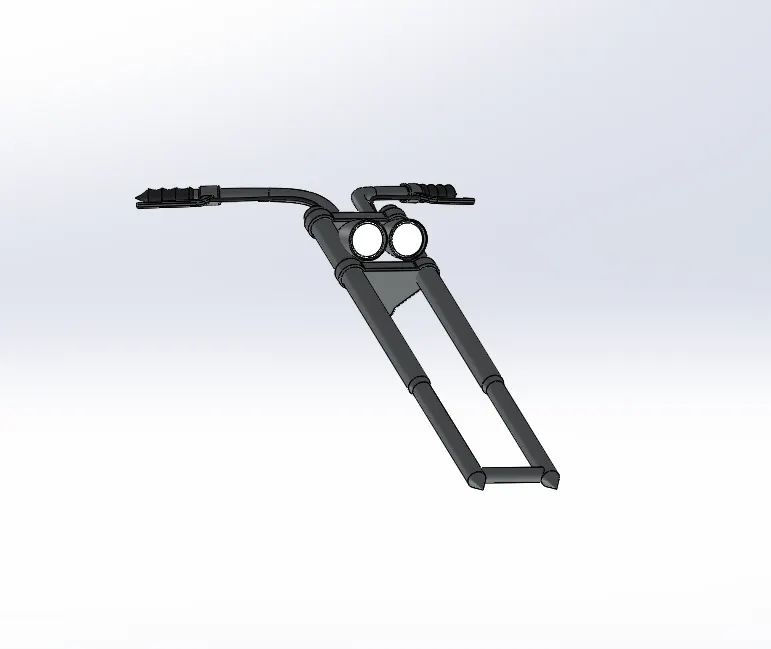
It is suspension component for front side of vehicle. It guides vehicle in motion stage. It holds front wheel on one side and on other side rider holds, to guide vehicle in correct manner.
Features Used:
1.Sketch
2.Revolve
3.Boss extrude
4.fillet
5.Linear Pattern
6.Cut Extrude
7.Dome
8.Cut Revolve
9.Project Curve
10.Sweep
Description:
Sweep:
It sweeps a closed profile along an open or closed path to create a solid feature.
11.Chassis:
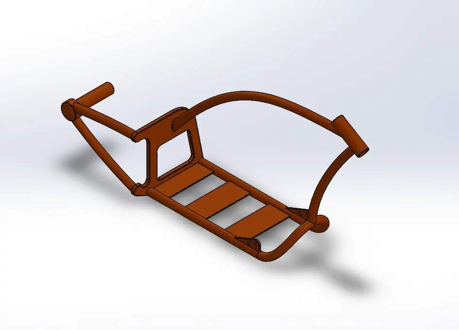
It is the skeleton of entire motorcycle. All the components of motor cycle like suspension, wheels, fuel tank, seats, etc.. are attached to this basic structure which lends motorcycle its strength and ability to handle well.
Features Used:
1.Sketch
2.Project Curve
3.Sweep
4.Mirror
5.Boss Extrude
6.Cut Extrude
7.Chamfer
8.Fillet
9.Split
10.Combine
11.Dome
12.Engine:
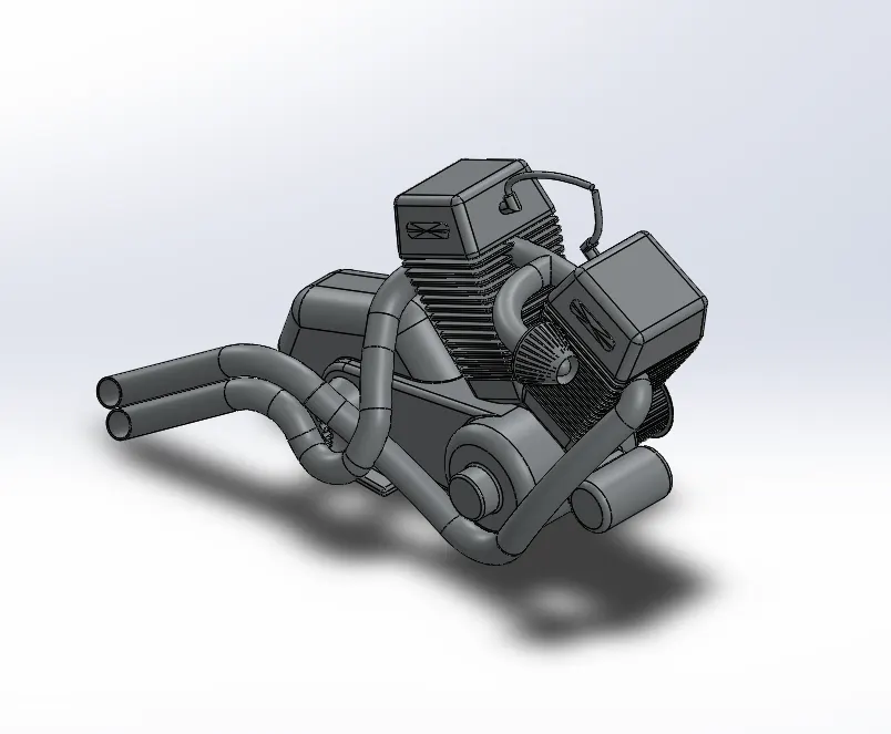
Engine is heart of motorcycle from where power is enerated. It converts heat energy into mechanical energy by burning the fuel and transfering generated power to wheel.
Features Used:
1.Sketch
2.Boss Extrude
3.Fillet
4.Revolve
5.Circular Pattern
6.Dome
7.Chamfer
8.Cut Extrude
9.Linear Pattren
10.Mirror
11.Combine
12.Project Curve
13.Composite Curve
14.Sweep
Description:
Composite Curve:
It combines selected edges, curves and sketches into single curve.
13.Gas Tank:
It is the fuel storage part of American Chopper which supplies required amount of fuel to engine.
Features Used:
1.Sketch
2.Surface Sweep
3.Surface Trim
4.Project Curve
5.Surface Loft
6.Boundary Surface
7.Mirror
8.Knit Surface
9.Split Line
10.Extrude Surface
11.Fillet
12.Sweep Cut
13.Shell
Description:
Surface Sweep:
It sweeps a closed profile along an open or closed path to create a surface feature.
Surface Trim:
It trims where a surface intersects with another surface, a plane or a sketch. Select a trim type, trim toom,and the surfaces to keep or remove.
Surface Loft:
It creates a lofted surface between two or more profiles or sketches. Specify start and end constraints and add guide curves to control the path shape.
Boundary Surface:
It creates a surface between profiles that can be tangent or curvature continuous in all directions. In the graphics area, use connectors or instant 3D drag handles to shape the boundary surface.
Knit Surface:
It combines two or more adjacent, nonintersecting surfaces into a single surface body.The surfaces must join at an edge.If the resulting knit surface encloses a volume, can create a solid body from the property manager.
Split Line:
It Projects a sketch to curved or planar faces, creating multiple several faces.
Extrude Surface:
It extrudes a sketch contours in one or two direction to create a surface feature.
Swept Cut:
It cuts a solid model by sweeping a closed profile along an open or closed path. A common usage is to create a cut around a cylindrical body.
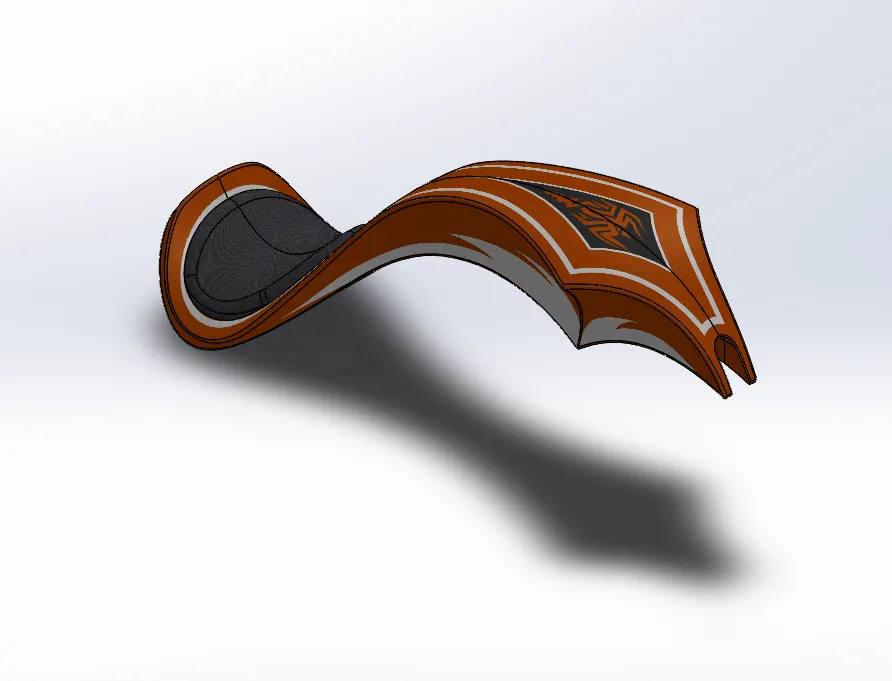
Assembly of American Chopper
After creating modelling of each and every part of American Chopper, assembling of American Chopper is done with required features and tools.
Features Used:
1.Insert Components
2.Mates
Description:
Insert Components:
It used to insert components of American Chopper to form assembly by mates.
Mates:
It connects to components by some features like concentric, coincident, parallel, tangent etc..
After assembling of American Chopper, decals are added to Gas Tank, Oil Tank and Rear Fender.
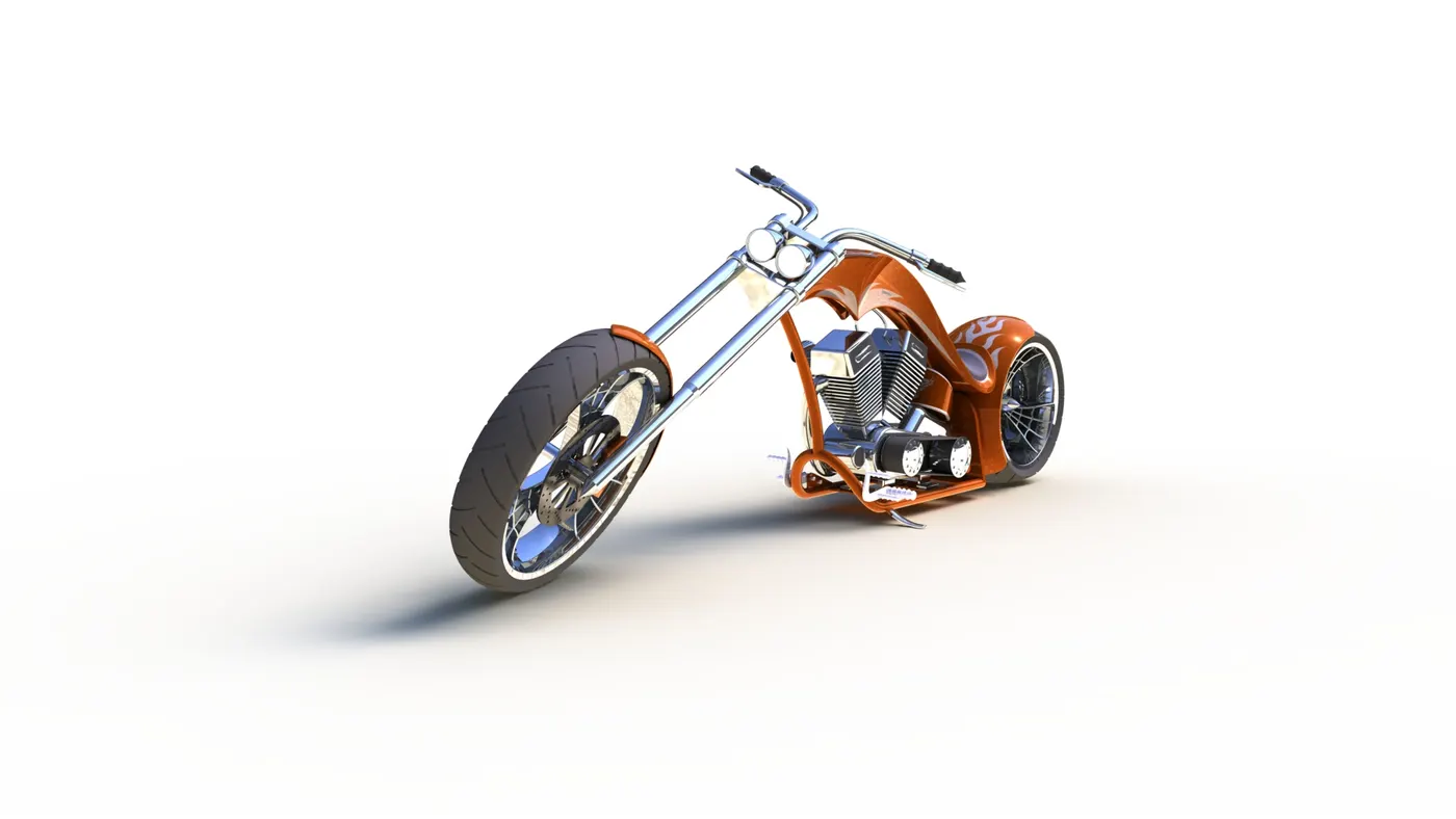
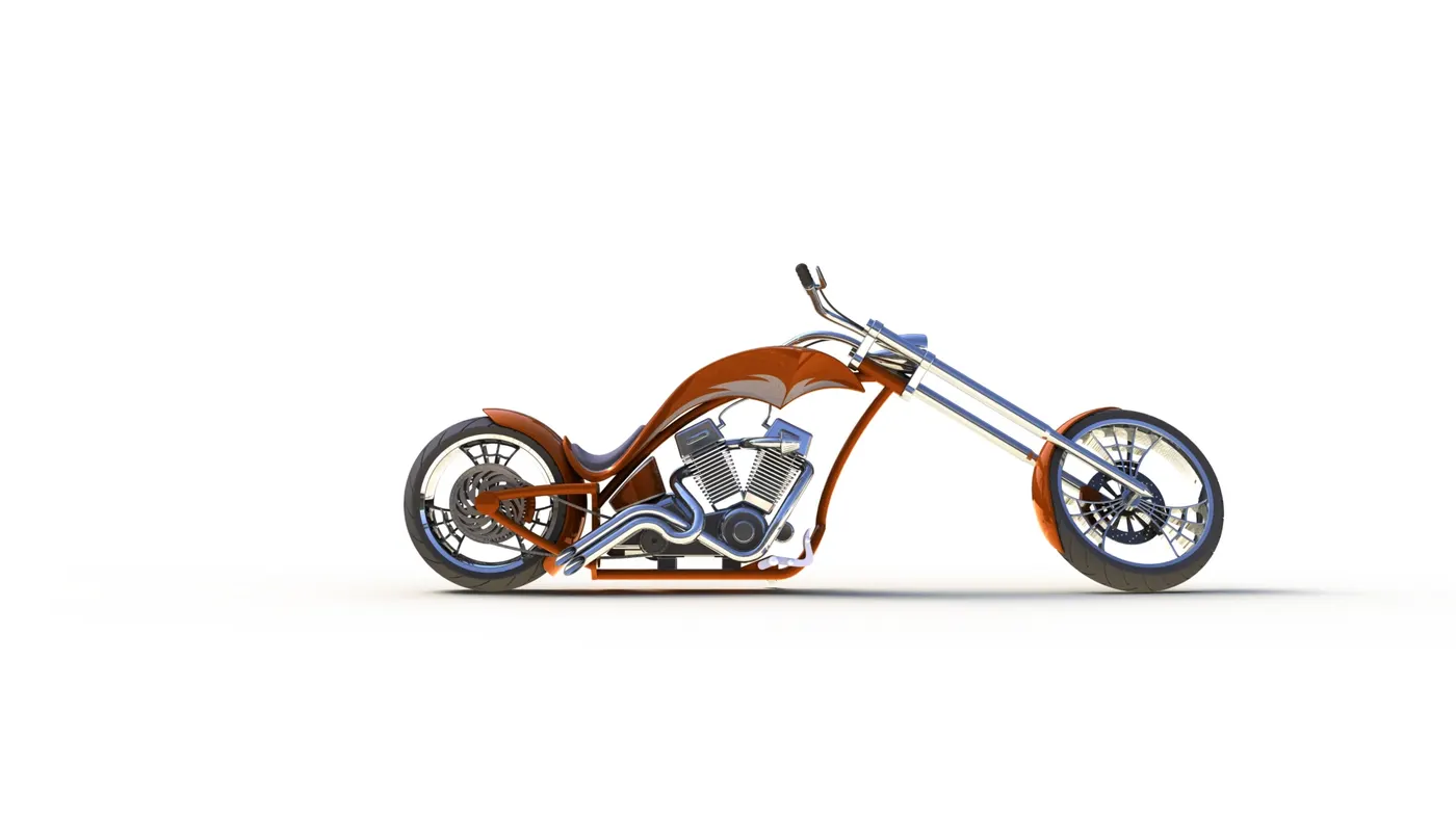
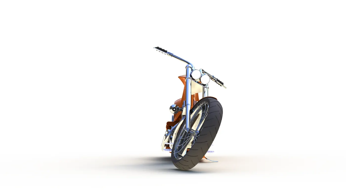
After adding decals to assembly of American Chopper , Rendering of American Chopper is done.
Rendering can be done by two methods:
1.Photoview 360
2.Solidworks Visualize
Conclusion:
The Part modelling of each and every part of American Chopper has been done with reqiured features.
The Assembly of American Chopper has been done with reqiured features.