Photo Realistic Rendering
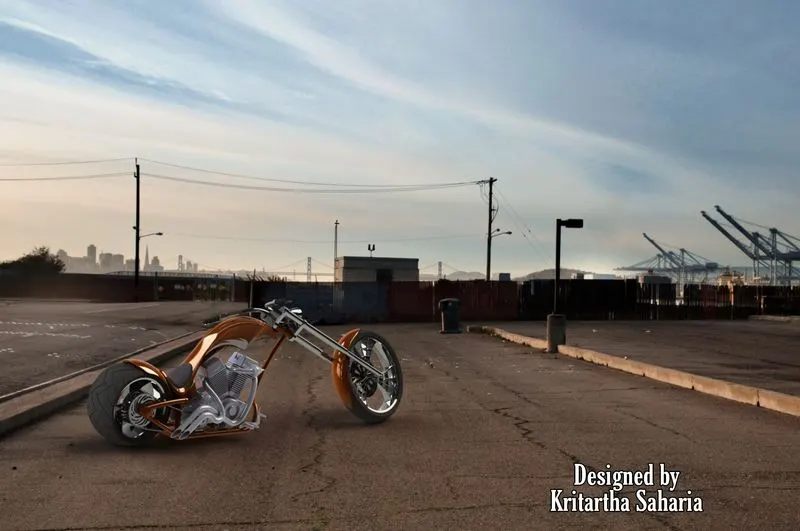
MODELLING AND RENDERING OF AMERICAN CHOPPER
Introduction
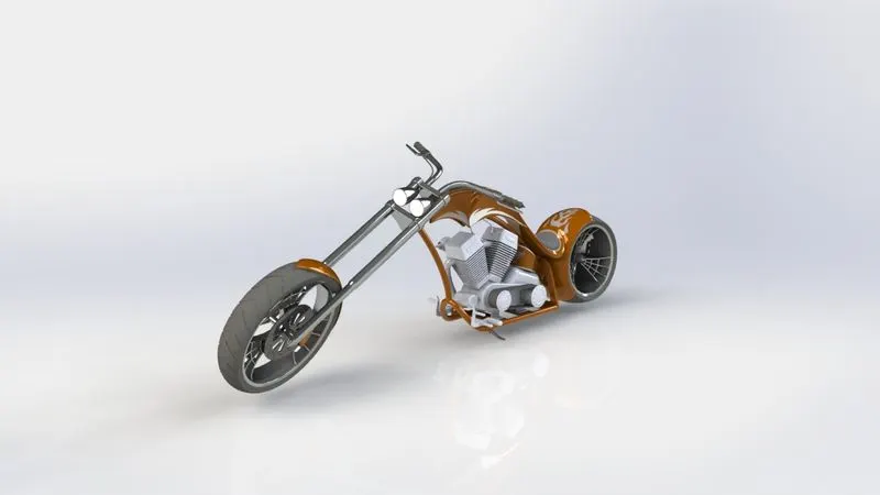
A chopper is a type of custom motorcycle that emerged in California in the late 1950s. The chopper is perhaps the most extreme of all custom styles, often using radically modified steering angles and lengthened forks for a stretched-out appearance. They can be built from an original motorcycle that is modified ("chopped") or built from scratch. Some of the characteristic features of choppers are long front ends with extended forks often coupled with an increased rake angle, hardtail frames (frames without rear suspension), very tall "ape hanger" or very short "drag" handlebars, lengthened or stretched frames, and larger than stock front wheels.
Part modeling
Modeling in general means creating a virtual prototype of an item It can be used for various purposes. Consider an engine of a car. It has hundreds of parts. Each part can be modeled separately and then can be assembled together to get the engine's final form. This type of modeling is called part modeling.
Objective
To create a model and photo-realistic rendering of an American Chopper by using Solidworks.
Parts of Chopper:
The Chopper consists of the following parts-
1. Chassis
2. Engine
3. Front fork
4. Pedal
5. Gas tank
6. Chain
7. Oil tank
8. Transmission belt
9. Front fender
10. Rear fender
11. Front wheel
12. Rear wheel
13. Kick stand
All the parts are designed separately and finally assembled together to get the final American Chopper.
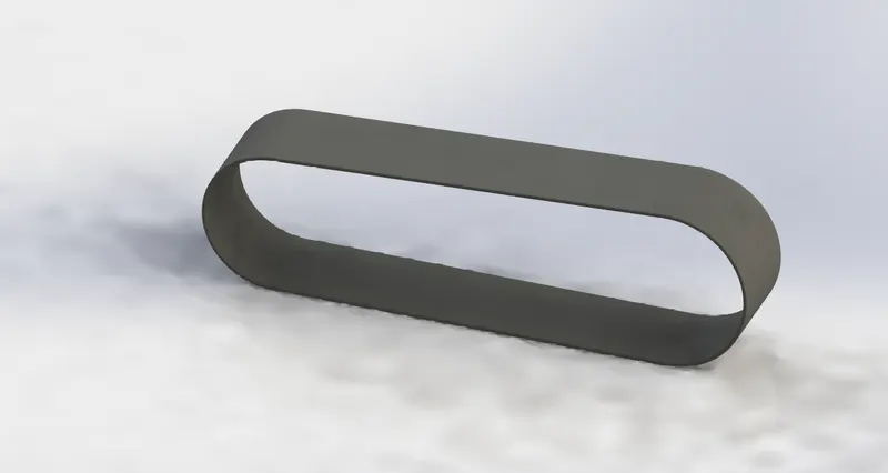
1. TRANSMISSION BELT
The Transmission Belt in the chopper is used to transmit the power from the Engine to the Gearbox.
Commands Used: Sketch, Offset Entities, Extrude, Fillet, Appearances
Sketch – It is the 2D representation with respect to the plane /view. In Solidworks different sketch options are available such as line, arc, circle, rectangle, and spline.
Offset Entities - It is used to create one or more sketch entities, selected model edges, or model faces by a specified distance.
Extrude – It is used to convert a 2d sketch into a 3d model.
Fillet - Fillet/Round creates a rounded internal or external face on the part. You can fillet all edges of a face, selected sets of faces, selected edges, or edge loops.
Appearances – It is used to apply color and optical properties to the entire part, or selected faces, features (including surfaces or curves), or bodies. You can also modify the color by manipulating the shaded appearance of the model.
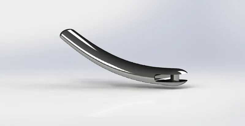
2. KICKSTAND
The Kick Stand is also known as Side Stand. It is used to support the chopper.
Commands Used: Sketch, Loft, Dome, Extrude, Extrude cut, Fillet, Split, Appearances.
Loft - The loft feature in SOLIDWORKS allows you to generate complex geometry in a single feature. It does this by interpolating surfaces between various cross-sections of a model. These cross-sections can be sketches, faces, or edges. In the loft interface, these cross-sections are considered “Loft Profiles”.
Dome - Dome, in architecture, the hemispherical structure evolved from the arch, usually forming a ceiling or roof over the surface/face being selected.
Extrude cut- The extrude cut feature is used to remove the unwanted material as per the modeled sketch, based on the design of the sketch the material is removed. You can cut in both directions and are mainly used for creating holes, channels, slots, etc.
Split - Split Line tool is used to project an entity (sketch, solid, surface, face, plane, or surface spline) onto other surfaces or curved/planar faces. You are also able to split faces on multiple bodies with one command.
3. FRONT FENDER
Fender (mudguard) is the American English term for the part of an automobile, motorcycle or other vehicle body that frames a wheel well (the fender underside). Its primary purpose is to prevent sand, mud, rocks, liquids, and other road spray from being thrown into the air by the rotating tire.
Commands Used: Sketch, Offset entities, Trim entities, Revolve, Dynamic mirror, Split, Appearances.
Trim entities - Select the trim entities based on the sketch you want to trim or extend.
Revolve - Revolve is the process of creating a revolved profile with reference to the sketch and the axis of rotation. The profile can be created with the revolution up to 360 axis rotation.
Dynamic mirror - This tool allows the user to mirror a sketch about a line while the user is creating their sketch.
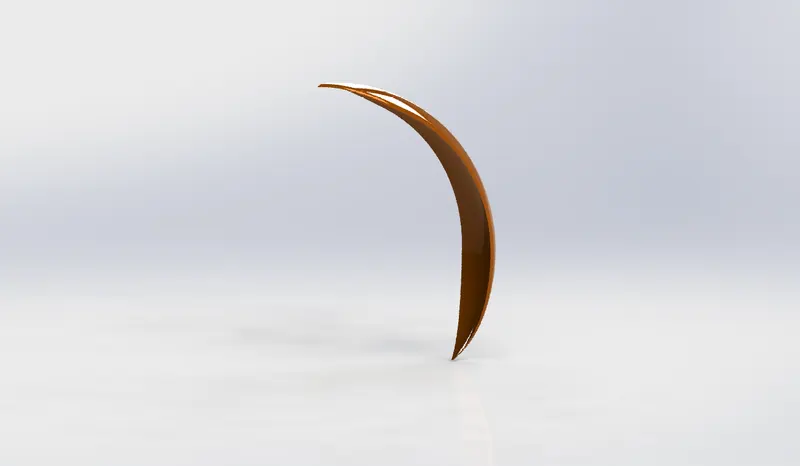
4. REAR FENDER
The use of the rear fender is the same as the front fender. The rear fender is mounted on the chassis of the rear part above the Rear Wheel.
Commands Used: Sketch, Offset entities, Trim entities, Revolve, Appearances.
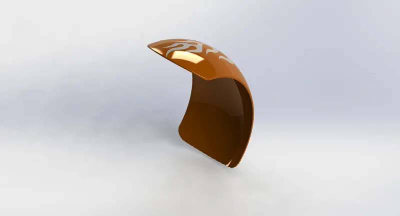
5. OIL TANK
The oil tank is used as a reservoir to meet the oil requirements of the engine and to lubricate the parts. It is hollow in nature.
Commands Used: Sketch, Extrude, Combine, Fillet, Shell, Appearances.
Combine - It is used to combine two or more bodies.
Shell - The shell tool hollows out a part, leaves open the faces you select, and creates thin-walled features on the remaining faces. If you do not select any face on the model, you can shell a solid part, creating a closed, hollow model. You can also shell a model using multiple thicknesses.
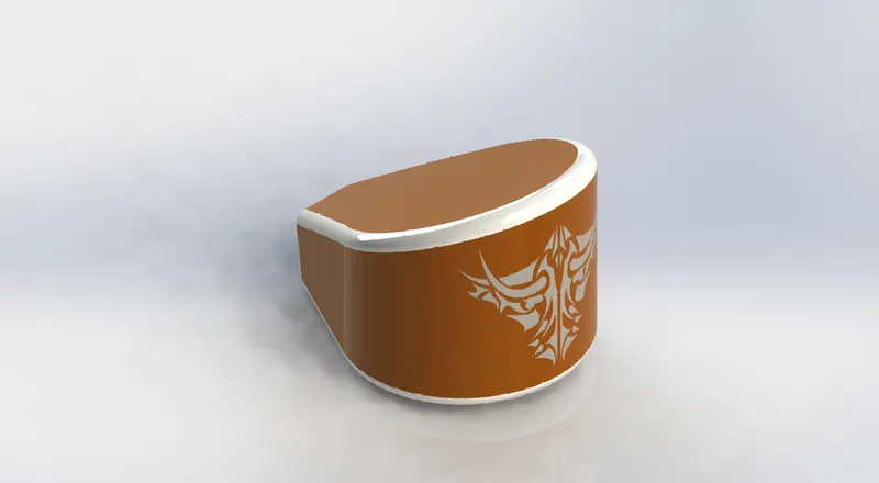
6. CHAIN
A chain is a type of transmission system that is used to transmit power from the Engine to the Rear Wheel. The chain is made of steel. The Sprocket is used to transmit the power to the chain. The sprocket is connected with the Shaft with the help of a key.
Commands Used: Sketch, Trim, Fillet, Blocks, Extrude, Patterns
Blocks - You can make, save, edit, and insert blocks for drawing items and sketch entities that you use often, such as standard notes, title blocks, label positions, and so on. You can attach blocks to geometry or to drawing views, and you can insert them into sheet formats.
Patterns – Pattern repeats the selected feature in an array based on a seed feature. You can create a linear, circular, curve driven, a fill pattern or use sketch points or table coordinates to create the pattern.
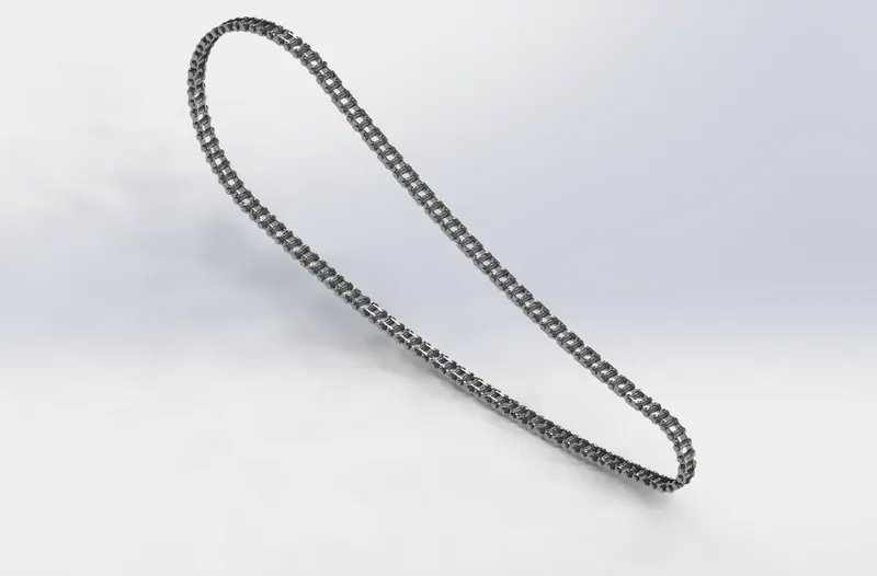
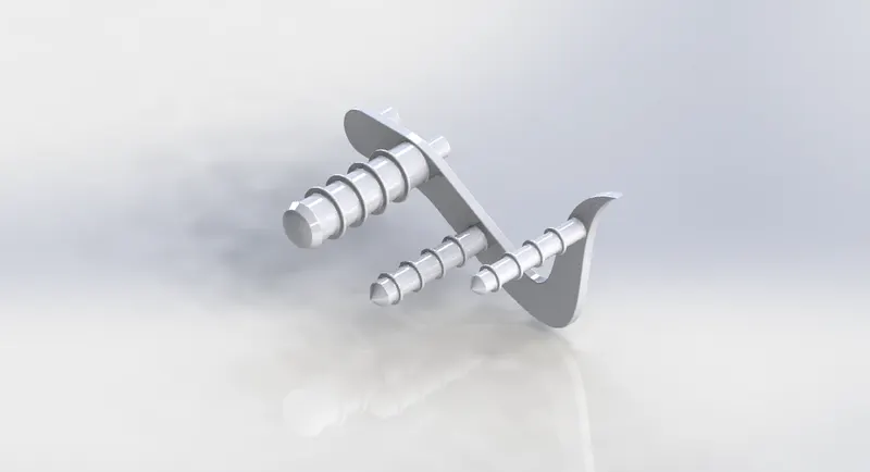
7. PEDAL
It is the external part attached to the chassis. Used to rest the foot of the rider on to it for the purpose of comfort.
Commands Used: Sketch, Extrude, Fillet, Linear pattern, Dome, Chamfer, Appearances.
Linear pattern- Linear patterns create multiple instances of one or more features that you can space uniformly along one or two linear paths.
Chamfer - A chamfer is a transitional edge between two faces of an object. Sometimes defined as a form of bevel, it is often created at a 45° angle between two adjoining right-angled faces.
8. FRONT WHEEL
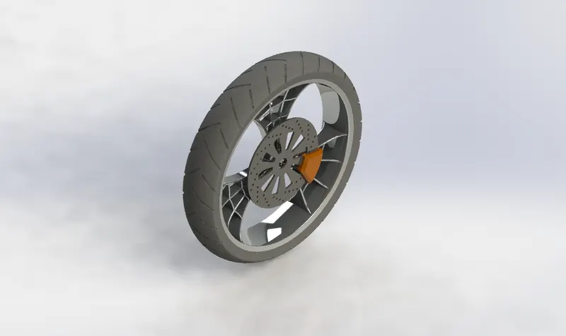
A wheel is a circular block of a hard and durable material whose center has been bored a circular hole through which is placed an axle bearing about which the wheel rotates when a moment is applied by gravity or torque to the wheel about its axis.
Commands Used: Sketch, Revolve, Trim, Fillet, Extrude, Revolve Cut, Linear Pattern, Chamfer, Cut Extrude, Circular Pattern, Appearances.
Revolve Cut - The Revolve cut command is used to cut a solid geometry by revolving about an axis. The axis may be a reference axis.
Circular Pattern - It is used to create multiple instances of one or more features that you can space uniformly around an axis.
9. REAR WHEEL
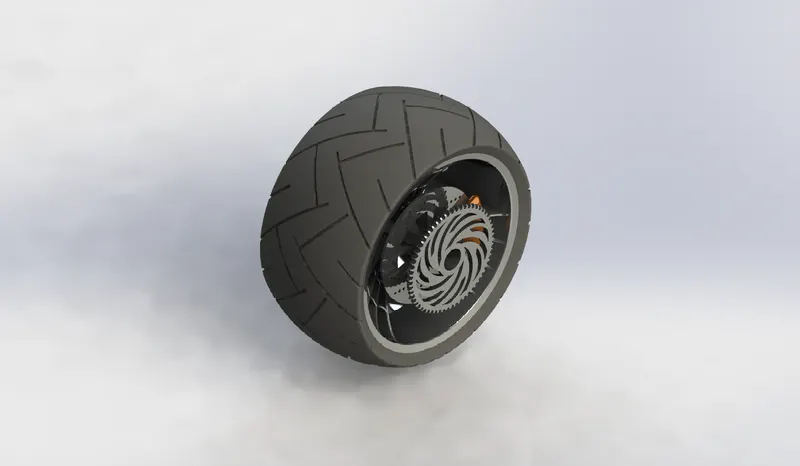
The rear wheel is situated at the rear portion of the chassis. The rear wheel carries the large sprocket and disc. The power is transmitted to the rear wheel from the gearbox through the chain.
Commands Used: Sketch, Revolve, Trim, Fillet, Extrude, Planes, Revolve cut, Linear pattern, Chamfer, Fillet, Extrude cut, Circular Pattern, Appearances.
10. FRONT FORK
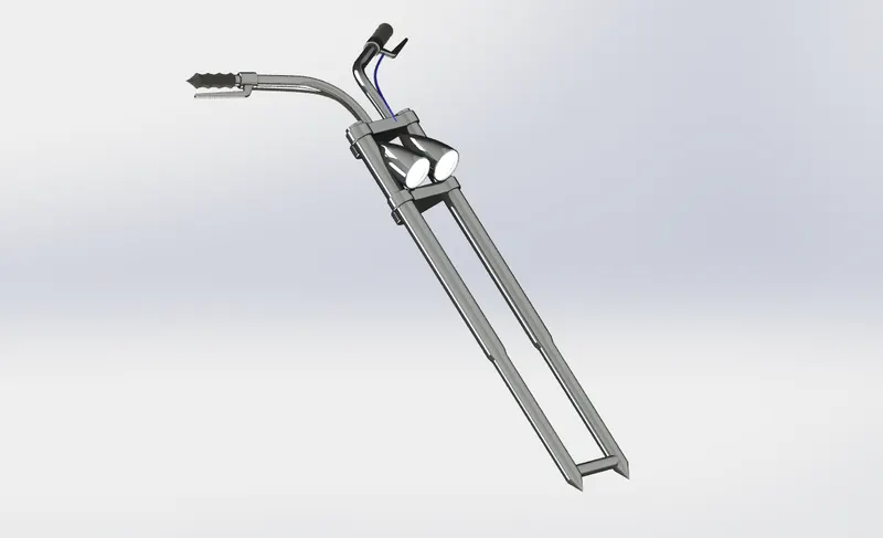
The front fork connects a motorcycle's front wheel and axle to its frame, typically via a yoke, also known as a triple clamp, which consists of an upper yoke joined to a lower yoke via a steering stem, a shaft that runs through the steering head, creating the steering axis. Most forks incorporate the front suspension and front brake and allow the front wheel to rotate about the steering axis so that the bike may be steered.
Commands Used: Sketch, Extrude, Trim, Revolve, Split, Plane, Convert entities, Move/Copy, Dome, Mirror, Combine, Project Curve, Sweep, Appearance.
Move/copy Body- Using this command you can move, rotate and copy solid ad surface bodies or place them using mates
Mirror- Mirroring is another way that Solid works can create a copy of an existing object. Additionally, you must choose a plane to mirror parts. In most cases, you need to create your own plane to have the mirror done the way you need.
Project Curve- A projected curve is typically used either in sweep and loft as a path or guide curve. They are made by using two sketches to a single curve or using a sketch to project on a surface.
Sweep- The Sweep command is used to create solid features by sweeping a closed profile along an open or closed path.
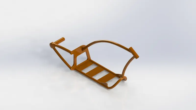
11. CHASSIS
A chassis is the load-bearing framework of a chopper that structurally supports its function and construction. All the parts of a vehicle's wheels, transmission, fuel tank, etc. are mounted on it.
Commands Used: Sketch, Offset, Convert entities, Project curve, Trim, Plane, Sweep, Split, Revolve, Cut extrude, Fillet, Combine, Appearance.
Convert Entities - You can create one or more curves in a sketch by projecting an edge, loop, face, curve, or external sketch contour, set of edges, or set of sketch curves onto the sketch plane.
12. ENGINE
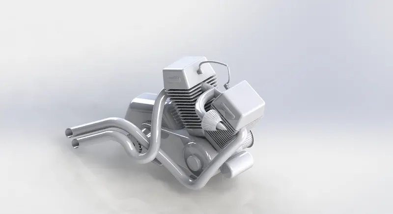
Motorcycle engines are generally classified by one of three characteristics the number of cylinders they possess, the capacity of their combustion chambers or the number of strokes in their power cycles.
Commands Used: Sketch, Convert entities, Trim, Revolve, Extrude, Extrude cut, Offset, Dome, Fillet, Project curve, Composite curve, Sweep, Mirror, Circular pattern, Split.
Composite curve - The composite curve tool provides the ability to create composite curves by combining two curves. The composite curve is the combination of the two projected curves.
13. GAS TANK
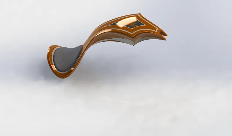
It acts as a reservoir to meet the fuel requirements of the chopper.
Commands Used: Sketch, Trim, Project curve, Convert entities, Sweep surface, Loft surface, Fill surface, Surface trim, Knit surface, Sweep cut, Fillet.
Sweep Surface - Creates a surface feature by sweeping an open or closed profile along an open or closed path.
Loft Surface - Loft Surfaces are surfaces generated by multiple 3D Curves or existing edges creating a smooth tangency between the selected curves.
Fill Surface - The Filled Surface feature constructs a surface patch with any number of sides, within a boundary defined by existing model edges, sketches, or curves, including composite curves.
Surface Trim - Primarily used to cut away material from a surface, and provides two modes: Standard and Mutual. In Standard mode, a single selection is defined as a Trim Tool, and target surfaces are trimmed accordingly. In Mutual mode, multiple surfaces are trimmed with respect to each other.
Surface Knit - It is used to combine two or more faces and surfaces into one.
ASSEMBLY
Assembly is done in the assembly environment by inserting all the modeled parts of the chopper using insert part option.
Parts of the chopper are fixed in the assembly environment by giving possible mate conditions or by fixing the planes.
You can build complex assemblies consisting of many components, which can be parts or other assemblies, called subassemblies. For most operations, the behavior of components is the same for both types.
Adding a component to an assembly creates a link between the assembly and the component. When SOLIDWORKS opens the assembly, it finds the component file to show it in the assembly. Changes in the component are automatically reflected in the assembly.
MATES
Mates create geometric relationships between assembly components. As you add mates, you define the allowable directions of linear or rotational motion of the components. You can move a component within its degrees of freedom, visualizing the assembly's behavior.
TYPES OF MATES
The various types of mates available in Solidworks are:-
- Standard Mates - Angles, Coincident, Concentric, Distance, Lock Parallel, Perpendicular, Tangent mates.
- Advanced Mates - Limit, Linear/Linear coupler, Path, Symmetry, Width mates.
- Mechanical Mates - Cam-follower, Gear, Hinge, Rack and Pinion, Screw, and Universal joint mates.
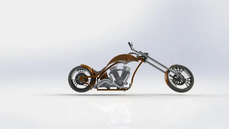
SIDE VIEW
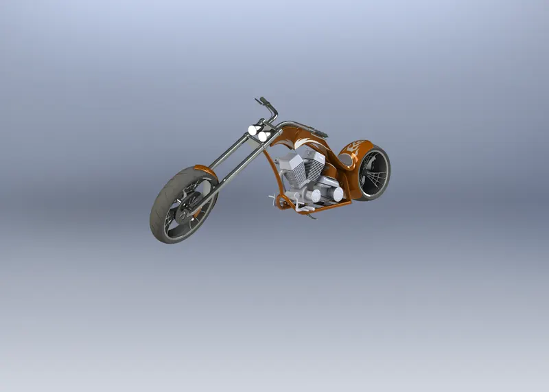
ISOMETRIC VIEW
FRONT VIEW
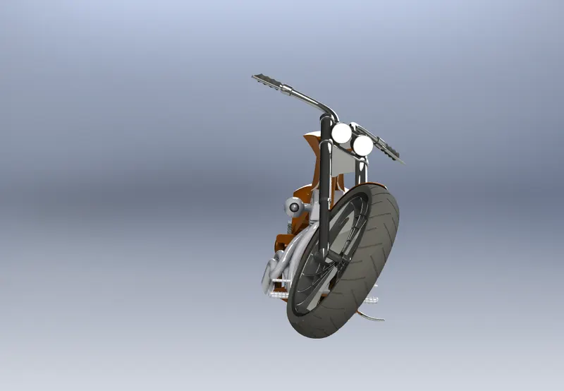
TOP VIEW
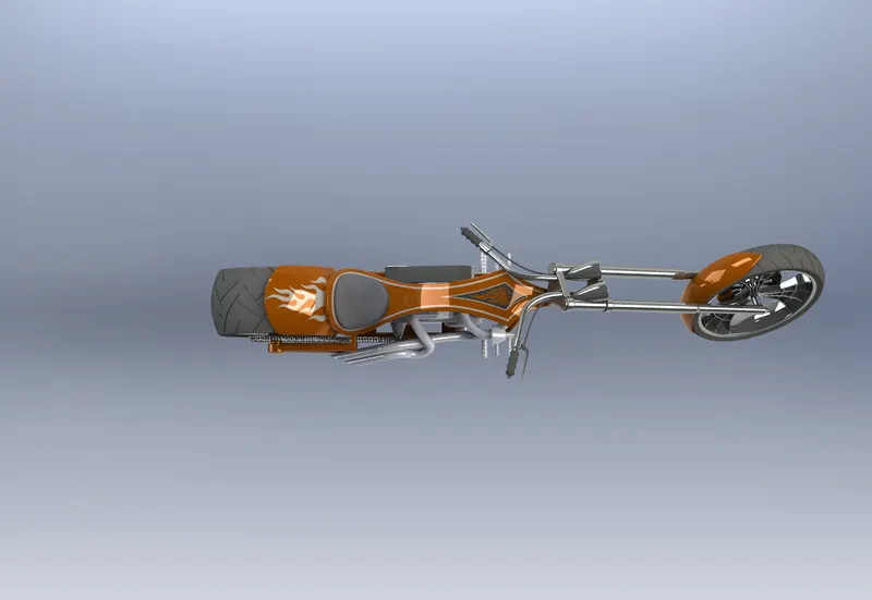
CAMERA VIEW
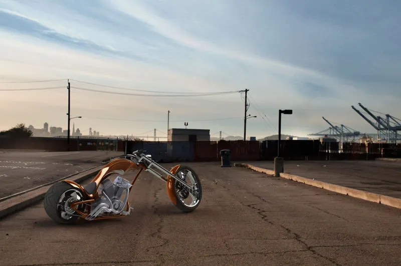
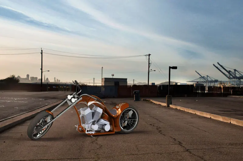
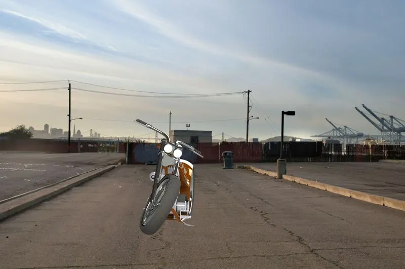
PHOTOREALISTIC RENDERING OF CHOPPER
Rendering is the process of creating realistic images of the Photorealistic model with the environment. Rendering has been done
with the help of photoview 360 because I had some issues with solid works visualization.
Conclusion
- All the exterior parts of the chopper are modeled successfully under SolidWorks modeling environment.
- All the parts are inserted into the assembly environment and the chopper is successfully assembled.
- The photorealistic image is successfully rendered with the use of the Photoview 360.