Photo Realistic Rendering
AMERICAN CHOPPER
ABSTRACT
This project involves design, assembly and rendering of American chopper model, American chopper is designed and assembled in solid works 2018 and rendered using photo view 360 and solid work visualize to give a realistic of its model.
MODELLING
The chopper is built through features based solid modelling and surface modelling features and consists of following components.
Transmission belt
Kick stand
Front fender
Rear fender
Oil tank
Chain
Pedal
Front wheel
Rear wheel
Front fork
Chassis
Engine
Gas tank
Transmission belt
It is used to transfer the power from engine to gearbox.
Features involved
Sketch
Offset
Extrude
Fillet
Procedure
Sketched in front plane and give horizontal vertical tangent relations to fully define sketch.
Using smart dimensions to sketch is defined with given dimensions and gave offset entity to the sketch.
The sketch is extruded and fillet is applied by selecting all the edges matte rubber is used as material reference.
Kick stand
Kick stand is used to support the chopper
Features involved
Loft
Dome
Extrude boss
Extrude cut
Split
Fillet
Procedure
Sketch ellipse at front plane. gave relation to orient inside the 2d sketch
Sketch splined at midplane(right). ensured the bottom spline handle is horizontal
Sketch a reference plane at top end of the spline and ensured it is normal to it.
Sketch ellipse at the reference plane. pierce relation is applied to the ellipse and spline.
Apply domes at the respective faces of ellipse.
Cutout at the larger end of part by sketching rectangle at mid plane. Give extrude cut and apply through all both options.
Create mid-point line at smaller end of the part and split the bottom face to make the part flat face.
Sketched circle at top plane to create pivot point. extrude the sketch to net surface. apply fillet
Change the appearance to chrome plate.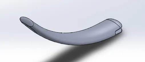
FRONT FENDER
Front fender is used to protect the front wheel from foreign particles and dust and mounted above the wheel blow the fork.
Features Involved
Sketch
Offset Entities
Trim Entities
Revolve
Split
PROCEDURE
Create a three-point arc and apply relations. Offset the entity to 6mm inside and enclose the edges of the arc using extend entities and power trim.
Draw a reference sketch for axis of revolution. and give revolve extrude. Using direction 1 and 2 option to make relevant sketch.
Apply appearance to sienna.
Sketch spline using dynamic mirror entities at the front edge of the fender and apply dimensions and ensure the spline handle is vertical to the part.
Check the curvature is clean and hide the show curvature. apply split tool to cut parts and followed same procedure for bottom edge.
Apply fillet at the edges of fender.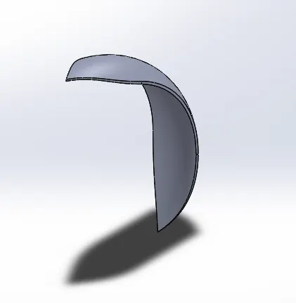
REAR FENDER
The Rear Fender is mounted above the Rear Wheel and has customized painting based on the theme of the copper.
Features Involved
Sketch
Offset Entities
Trim Entities
Revolve Extrude
Split
PROCEDURE
A three-point arc was created as per the given geometry. The sketch was revolved using both the directions 10mm in one side and 140 mm on other.
Using three-point arc the part is spilt and fillet is applied.
Shell feature is used on the inner side of the fender.
Graphic rear fender file is imported and sketch is used to create a projected image using curve split line and the face is changed to standard white color appearance.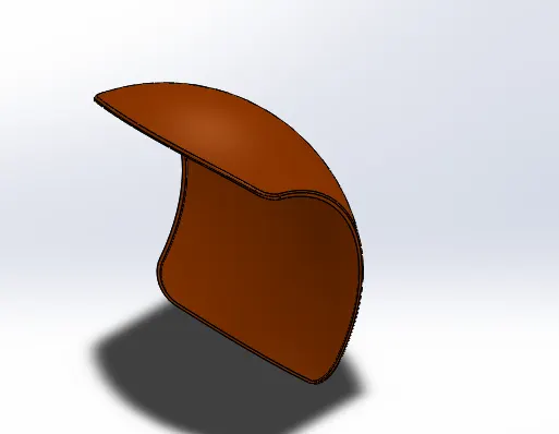
OIL TANK
Oil Tank is Hollow Solid Model created using following features
Features Involved
Boss Extrude
Combine
Fillet
Shell
PROCEDURE
A 2D Sketch is created and then extruded on both directions
A new sketch is created and extruded through all both the directions
Combine feature is used to common the both extrudes Fillets are applied at the edges and Shell feature is applied with thickness and previewed using cut section to ensure shell is applied
Appearance are changed to sienna, white at the edges and for the graphic oil tank.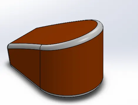
CHAIN
This model is approached through creating Sketch blocks and Linear Pattern and mirrored along the Front plane.
Features involved
Sketch Blocks
Extrude
Curve Driven Pattern
Mirror
PROCEDURE
A runaway sketch is created at the midplane and the is used to save as separate blocks a chain 1 and 2.
The blocks are inserted on to the 2D sketch created on the midplane and applied certain relations to make coincident with the curve.
The blocks are then extruded and fillets are applied at the faces of the pin.
Linear pattern is applied along the curve (Curve driven pattern) and some extrudes are drawn manually to perfectly align with the chain path.
Later the solid bodies are classified into chain. plates and pin in separate folders and the chain plates are mirrored using mirror entity.
Chrome Appearance is applied to the chain.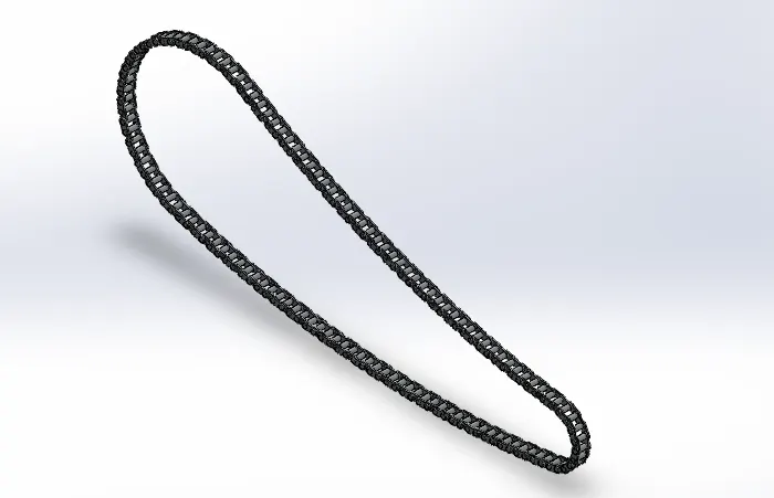
PEDAL
The Pedal model is mounted external to the chassis on both sides which provides as a footrest to the riders.
Features involved
Extrude
Fillet
Linear Pattern
PROCEDURE
2D sketch is extruded and a new sketch is created and Revolve Boss feature is applied.
Dome is applied at the end face of the revolved part and chamfer (asymmetric in both directions) applied to the other two parts
Fillets are applied and new sketch is created using offset entity and extruded by offset from face
Fillets are applied to the newly created extrude feature and Linear pattern is applied to four instances
Ensure all the edges are applied with necessary fillet.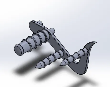
REAR WHEEL
Rear Wheel are broad and are one of the most custom-made components in chopper and has various rim style but chopper is famous for its spider webbed designed with its chromium alloy.
Features involved
Revolve
Extrude
Cut Extrude
Cut Revolve
Combine
Circular Pattern
Fillet
Chamfer
PROCEDURE
Five Solid bodies are designed namely Rim, Rotor, Caliper, Sprocket, Tyre.
Rim is developed using Revolve and circular pattern is applied to make spider web shaped rim wheel.
Rotor is Designed and necessary pattern is sketched.
A Caliper is designed on the rotor by applying necessary Chamfer features.
Sprocket is sketched over the rim for chain assembly.
Finally, the Tyre is designed above the Rim by applying cut extrude pattern.
Appearances are changed and Part is saved.
FRONT WHEEL
Front Wheel are designed the same way as Rear Wheel and attached to the front fork with fixed rotation along the fork to allow the chopper to make turn.
The Wheel rim also has a spider web shaped and has matte rubber tire with Profile cutout to provide friction between the tyre and the road.
FRONT FORK
Front fork is steering of the American chopper and front wheel is mounted on the front fork.
Features involved
Revolve
Boss Extrude
Linear Pattern
Cut Extrude
Dome
Cut Revolve
Sweep
Combine
Mirror
Fillet
Projected Curve
PROCEDURE
This model is done by creating mirror features by sketching one half
Front Axle frame is designed by applying extrude revolve and cut solid bodies.
The handle bar frame is designed with projected curve feature to sketch. And sweep based on the circle and the projected curve
The headlight model is designed and dome, chamfer features applied.
Finally, the model is mirrored and necessary appearance are given to different parts. Visual Propagation is checked to apply the appearances on both sides.
Luminous intensity is applied to the head light model for effective display when doing rendering.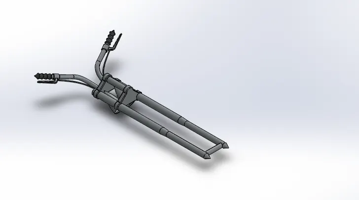
CHASSIS
This is the base model of the chopper and housed various components like Engine. This model is approached through creating multiple spline entities and combining it to a composite curve.
Features involved
Offset Entities
Convert Entities
Project Curve
Trim
Sweep Bose
Split
Revolve
Extrude Cut
Extrude Boss
Fillet
Combine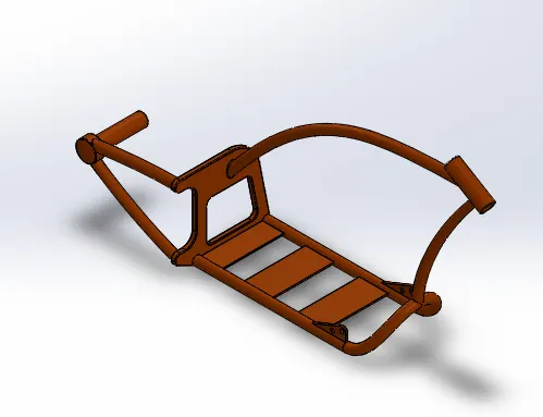
ENGINE
Chopper Engine is designed using series of Projected Curves and Composite Curves. This complex Solid model has following parts.
Cooling Fins
Exhaust Pipe
Gear Box
Sprocket for Chain Transmission
Engine Case
Spark Plugs
Features involved
Extrude
Extrude Cut
Thin Extrude
Chamfer
Project Curve
Linear Pattern
Circular Pattern
Revolve
Mirror
Dome
Sweep
GAS TANK
The Gas Tank is approached using Surface Modelling Features and converted to rigid solid body after enclosing as a closed surface model.
The Gas tank provides the Seating grip for the Rider and looks stunning with different themes and sketches with different choppers.
The main purpose is to store the Fuel and hence the solid body is shelled to appropriate thickness.
Features involved
Surface Sweep
Surface Trim
Surface Loft
Boundary Surface
Surface Knit
Sweep cut
Fillet
Mirror
Shell
The Decals are added to the tank using Photo view 360 and appearances are given as sienna car pain for main body.
ASSEMBLY
Chassis is the first component inserted in to the assembly model and fixed with respect to the three planes.
Based on Chassis all other models are assembled using appropriate mates to fully define the assembly.
PROCEDURE
Engine is placed on the bottom of the chassis.
Pedal is attached to side of the chassis and the component is mirrored to the other side.
Kickstand is attached to the left bottom side of chassis.
Transmission belt is fixed between the two gear drives and the ensured that tooth are meshed properly.
Oil Tank is placed above the Engine Casing.
Rear Wheel is attached to the End frame of the Chassis and Rear Fender is placed using appropriate concentric mates.
Chain is Inserted between the rear wheel sprocket and Engine Sprocket.
The Gas Tank is placed over the Top Frame.
The Front Axle is attached to the front shaft of the chassis.
Finally, the Front Wheel and Front fender are attached to the axle
The Axle, Front Wheel and Fender are given a angular mate to move on both sides.
The Kickstand, Front Wheel and Rear Wheel are grounded to the Plane to create a realistic model view.
Design and Assembly of American Chopper using Solid works and Photo realistic rendering using Visualize.
RENDERING
Different scenes were created by adding new camera views.
Visualize project is used to create realistic environment and the rendering is done by adjusting the casualization, brightness, gamma, depth of view and focus with clean and high definition rendering image backgrounds.
The rendered images are attached below with different environment and backgrounds.