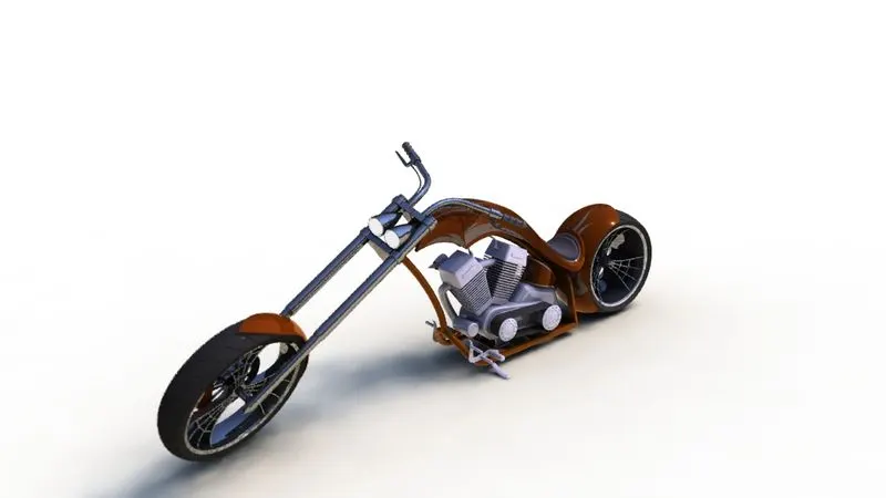
Photo Realistic Rendering
REPORT
Title: -
Design and modelling of American chopper.
Objective: -
To create an American chopper assembly by using solid works.
Introduction: -
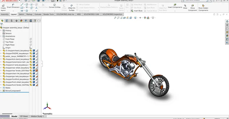
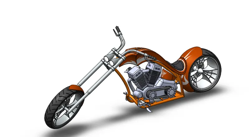
To design the American chopper and its parts by using solidworks.it shows the assembly, part models, different views, materials, dimensions, and design methods and features and realistic views of chopper.
To build the assembly and sub-assemblies by using solid works the way the model exists once it is manufacturing.
Design process: -
The design methodology usually involves the following steps.
The design methodology usually involves the following steps.
Description
The chopper consists of the following parts
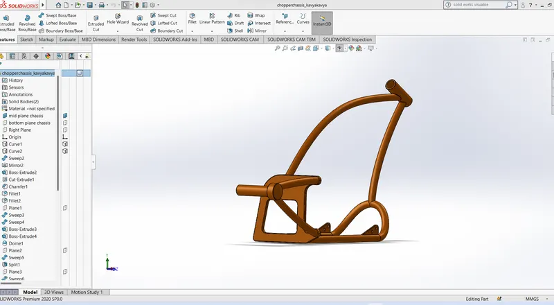
- Chassis:
commands used for chassis: -
- Sweep: A sweep is a tool that creates a solid, a cut or a surface feature by moving a profile along a path.
- Extrude: extrude is a feature which uses to convert 2d sketches into 3d models.
- Revolve: Revolves add or remove material by revolving one or more profiles around a centreline
- Projected curve: To create a 3D curve that represents the intersection of two extruded surfaces generated by creating sketches on two intersecting planes.
- Split: The solid works Split Line tool is used to project an entity sketch, solid, surface, face, plane, or surface spline onto other surfaces or curved/planar faces.
- Mirror: Creates a copy of a feature, (or multiple features), mirrored about a face or a plane.
- Appearance: An appearance defines the visual properties of a model, including color and texture.
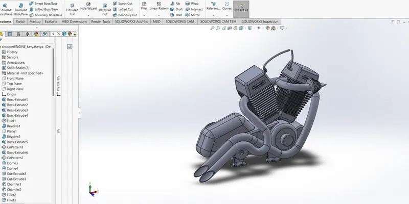
- Engine:
commands used for engine: -
- Extrude: extrude is a feature which uses to convert 2d sketches into 3d models.
- Revolve: Revolves add or remove material by revolving one or more profiles around a centreline
- Sweep: A sweep is a tool that creates a solid, a cut or a surface feature by moving a profile along a path.
- swept cut: Swept Cut command in Solid works is very special command that you can do your eccentric cutting operations through a 3D geometry in Solid works.
- Extrude cut: Extruded cut feature removes material from the part.
- Fillet: Fillet/Round creates a rounded internal or external face on the part.
- Chamfer: The chamfer tool creates a bevelled feature on selected edges, faces, or a vertex.
- Dome: It creates a dome that is tangent to the adjacent cylindrical or conical face.
- Combine: To use this feature, we will select the common button, and then under Bodies to Combine, select the two bodies.
- convert entities: You can create one or more curves in a sketch by projecting an edge, loop, face, curve, or external sketch contour, set of edges, or set of sketch curves onto the sketch plane.
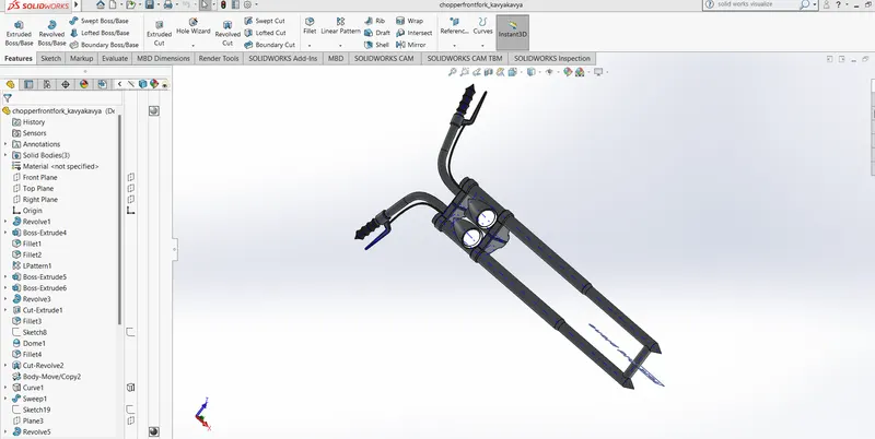
- Front Fork:
commands used for front fork: -
- Revolve: Revolves add or remove material by revolving one or more profiles around a centreline.
- spline: A Spline sketch is defined by its continuously changing curvature. Points are placed to shape the curve.
- Planes: to define planes in different ways in terms of geometry, we can start learning how to define new planes in SOLIDWORKS. To illustrate this, we will create the following model:
- Mirror: Creates a copy of a feature, (or multiple features), mirrored about a face or a plane.
- projected curve: it allows the user to create curves by projecting the selected curves onto the face of the user-defined solid or surface geometry.
- Combine: To use this feature, we will select the common button, and then under Bodies to Combine, select the two bodies.
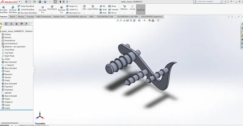
- Pedal
commands used for pedal: -
- Revolve: Revolves add or remove material by revolving one or more profiles around a centreline.
- swept cut: Swept Cut command in Solid works is very special command that you can do your eccentric cutting operations through a 3D geometry in Solid works.
- spline: A Spline sketch is defined by its continuously changing curvature
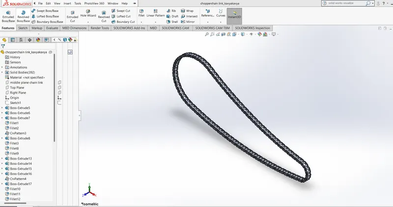
- Chain: -
commands used for chain-
- Extrude: extrude is a feature which uses to convert 2d sketches into 3d models.
- Extrude cut: Extruded cut feature removes material from the part.
- Trim: Trims open sketch entities that lie inside two bounding entities. Trimmingwith Trim Away Outside. Trims open sketch entities outside of two bounding entities.
- linear pattern: to create multiple instances of one or more features that you can space uniformly along one or two linear paths
- curve driven pattern: The Curve Driven Patterntool allows you to create patterns along a planar or 3D curve.
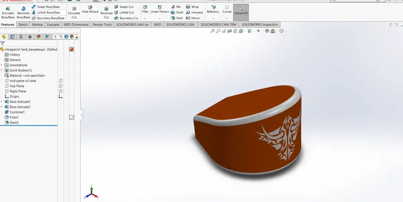
- Oil Tank: -
commands used for chain-
- Sweep: A sweep is a tool that creates a solid, a cut or a surface feature by moving a profile along a path.
- Combine: To use this feature, we will select the common button, and then under Bodies to Combine, select the two bodies.
- Fillet: Fillet/Round creates a rounded internal or external face on the part.
- Extrude cut: Extruded cut feature removes material from the part
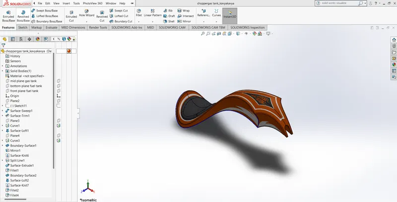
- Gas Tank: -
commands used for chain-
- surface loft: The loft feature creates a shape by making transitions between multiple profiles and guide curves.
- surface sweep: a sweep is a tool that creates a solid, a cut or a surface feature by moving a profile along a path.
- boundary surface: The boundary surface feature lets you create surfaces that can be tangent or curvature continuous in both directions.
- knit surface: Knit Surfacetool to combine two or more faces and surfaces into one.
- projected curve: it allows the user to create curves by projecting the selected curves onto the face of the user-defined solid or surface geometry.
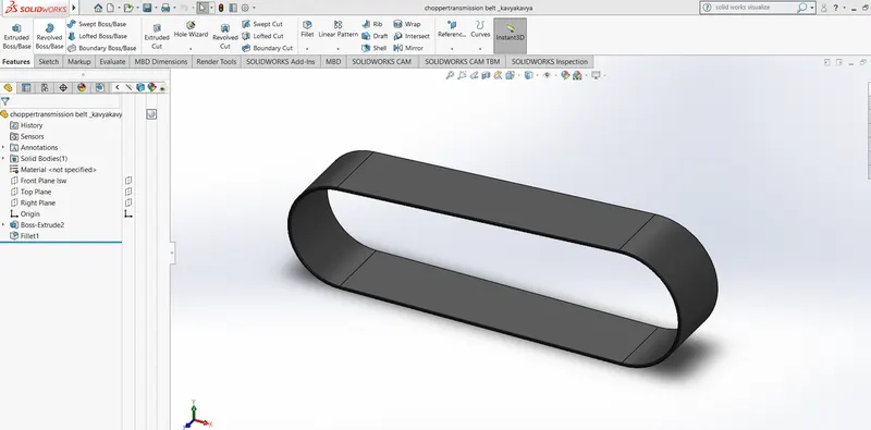
- Transmission Belt: -
commands used for transmission belt: -
- Extrude: extrude is a feature which uses to convert 2d sketches into 3d models.
- 2d sketch: A sketchis almost always the first step in designing a new part.
- Fillet: Fillet/Round creates a rounded internal or external face on the part.
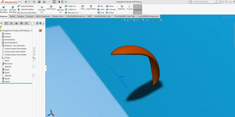
- Front fender: -
commands used for front fender: -
- 2d sketch: A sketchis almost always the first step in designing a new part.
- Extrude: extrude is a feature which uses to convert 2d sketches into 3d models.
- Extrude cut: Extruded cut feature removes material from the part
- spline: A Spline sketch is defined by its continuously changing curvature
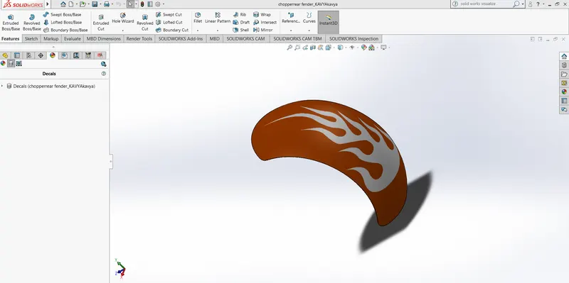
- Rear Fender: -
commands used rear fender
- 2d sketch: A sketchis almost always the first step in designing a new part.
- Extrude: extrude is a feature which uses to convert 2d sketches into 3d models.
- Extrude cut: Extruded cut feature removes material from the part
- spline: A Spline sketch is defined by its continuously changing curvature.
- Decal: A decal is a 2D image applied to a model
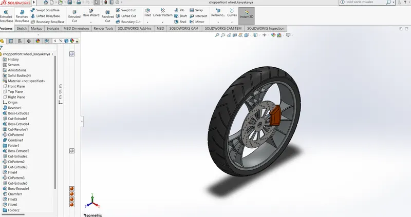
- Front wheel: -
commands used front wheel
- Revolve: Revolves add or remove material by revolving one or more profiles around a centreline
- revolve cut: The revolved cut feature allows us to take a basic shape and revolve it around a centre line to create a cut into parts or multiple parts.
- Extrude: extrude is a feature which uses to convert 2d sketches into 3d models.
- circular pattern: Use circular patterns to create multiple instances of one or more features that you can space uniformly around an axis.
- Offset: Offset entities takes a copy of your existing geometry and copies it at an offset. Instead of recreating geometry, you can use this to quickly sketch based on model geometry
- Extrude cut: Extruded cut feature removes material from the part
- Fillet: Fillet/Round creates a rounded internal or external face on the part.
- Combine: To use this feature, we will select the common button, and then under Bodies to Combine, select the two bodies.
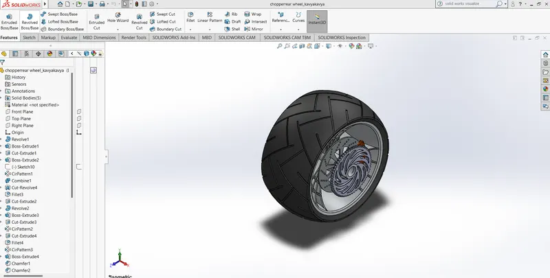
- Rear wheel: -
commands used front wheel.
- Revolve: Revolves add or remove material by revolving one or more profiles around a centreline
- revolve cut: The revolved cut feature allows us to take a basic shape and revolve it around a centre line to create a cut into parts or multiple parts.
- Extrude: extrude is a feature which uses to convert 2d sketches into 3d models.
- circular pattern: Use circular patterns to create multiple instances of one or more features that you can space uniformly around an axis.
- Offset: Offset entities takes a copy of your existing geometry and copies it at an offset. Instead of recreating geometry, you can use this to quickly sketch based on model geometry
- Extrude cut: Extruded cut feature removes material from the part
- Fillet: Fillet/Round creates a rounded internal or external face on the part.
- Combine: To use this feature, we will select the common button, and then under Bodies to Combine, select the two bodies.
Kick stand: -
commands used front wheel
- spline: A Spline sketch is defined by its continuously changing curvature
- Revolve: Revolves add or remove material by revolving one or more profiles around a centreline
- Fillet: Fillet/Round creates a rounded internal or external face on the part
Assembly: -
assembly is defined as the parts to be drawn individually a combined together
commands used for assembly
Mates: Mates create geometric relationships between assembly components.
Types of mates:
- concentric mate
- tangent mates
- parallel mates
- distance mate
- limit angles
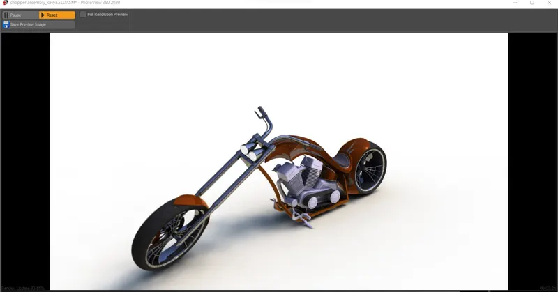
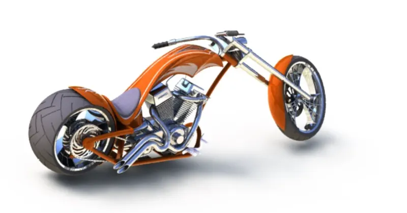
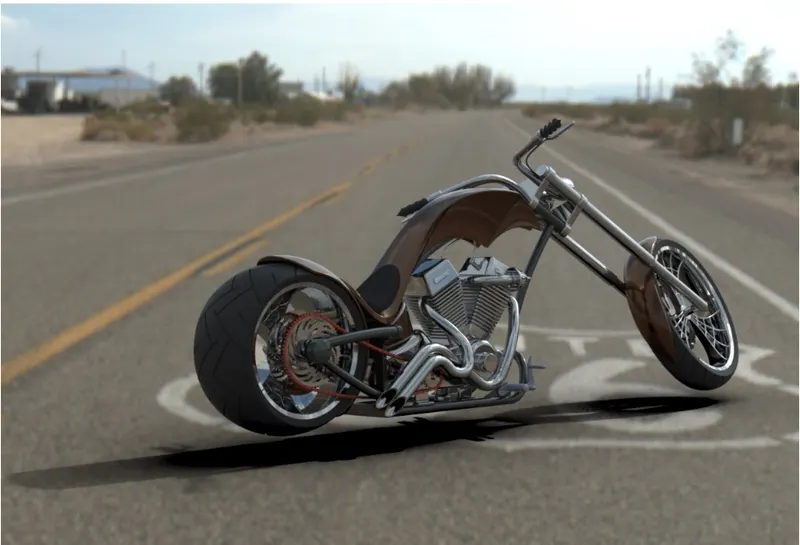
rendering: -
Photo View 360 is a solid works add-in that produces photo-realistic renderings of SOLIDWORKS models. The rendered image incorporates the appearances, lighting, scene, and decals included with the model. Photo View 360 is available with solid works Professional or SOLIDWORKS Premium.
Conclusion: -
Modelling, assembly and rendering of an American chopper is successfully completed by using solid works.