Advanced Sheet Metal Design Using NX Cad Challenge_1_Casing Design
TITLE:-
To create a model by using advance sheet metal by using.to understand the basic graphical user interference of siemens nx. and learn about the inustrial approch of the sheet metal using siemens nx.
objective:-
1.The objective of this project is to create a casing design by using advance sheet metal with different commands.
2. to understand the basic tools and commands of the sheet metal and its application.
3. to understand the industrial approch of the sheet metal using siemens nx
introduction:-
the sheet metal becoms the most essential product which is available in everywhere including cars,aerospace& house hold things.the thickness of the sheet metal ranged between 0.5mm to 6mm which is obtained from industrial process which termed as bending,coining,forming,punching,stamping.
procedure:-
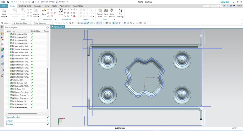
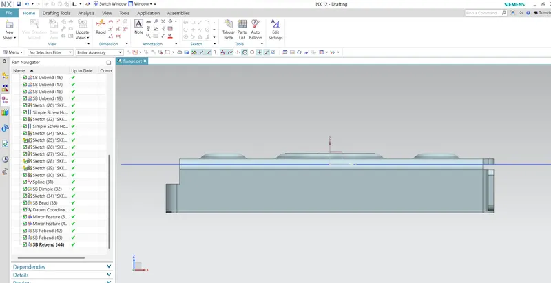
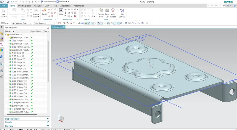
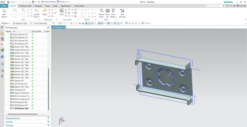
The model have been started by creating a sketch and completd as required shape and used flange feature to mae the part bend as first,then drawn a curve with multiple points by using studio spline and create a dimple thickness of 1mm, and create sketch with 5mm dia hole and create a bead of 1mm and tolerance of 5mm, by using mirror feature i created a 4 bends at the corners othe flane and rebend the edges.
Design methodology:-
1. open nx 12
2. open new file
3. create XY plane by using co-ordinate system
4. create rectangle by given dimensions.
5. changing the parameters.
6. add a solid sheet and cut out
7. create a bend by using the given parameters.
8. create a flange by the given parameters
9. break the corners
10. unbend the flange.
11. add a holes by the give dimensions.
12. add a studio spline & add a dimple.
13. add a beads
14. to add a bend on four corners by using mirror feature.
15. and create a re-bend
description:-
1. tab:-
Create the bottom of the Base using Tab command on a base Sketch.the bae platform of any sheetmetal model or base feature of any sheet metal provides a shape to the sketch by providing some thickness to the sketch in solid form.the tab is the parent model for the rest of the model which will be created under consideration of the parent feature which is the tab.
2. cut out:-
Cutting faces will be perpendicular to the sheet metal surface. the casing design contains a rectangular cut-out which will be performed by specifying sketch or3D curved to the normal cut-out feature.
3. bend:-
bends the sheet metal model through an angle. this feature performs by specifying a 2D sketch from which the sheet metal model can bend from its original position at angle by specifying.the casing design is parallel and symmetrical to the axis from which the sheet metal model can bend.
4. flange:-
this command adds a flat flange at angle to a planar surface and adds bend between the twoo sides. it can be created by selecting the planar or the edge of the sheet metal model at a specific length and angle. the casing design has 4 flanges at an angle of 45 degrees.
5. breaking corners:-
it creates a smoth edges of the flanges. break corners used in the casing design to prevent the model from cracks or any features.ss,cut, and surface modelling.
6. studio spline:-
Use the Studio Spline command to dynamically create splines using either points or poles.
7. move curves:-
Move curves or points vertically or horizontally without snapping.
8. Dimple:-
The Dimple command to lift an area of the model inside a sketch that simulates a stamping tool. this feature is used to provide strength to the sheet metal because the thickness of the sheet metal is not much by which the shape can get deormed.
9. bead:-
Beads are the features added in sheet metal components in order to increase the stiffness of the component. this provides strength to the sheet metal model to prevent unexpected deformation.it doesnot depend on any closed or opened sketch profile to perform the feature in 3D or it provides stiffness to the model.the casing design contains four circular beads of 1mm depth and radius which beads
1o. mirror:-
Using this feature takes less time than drawing and extruding a whole other triangle. When creating symmetric shapes with more complex structures, it also ensures that the lines and angles are completely symmetric and that there are no mistakes in that regard.
11. drafting:-
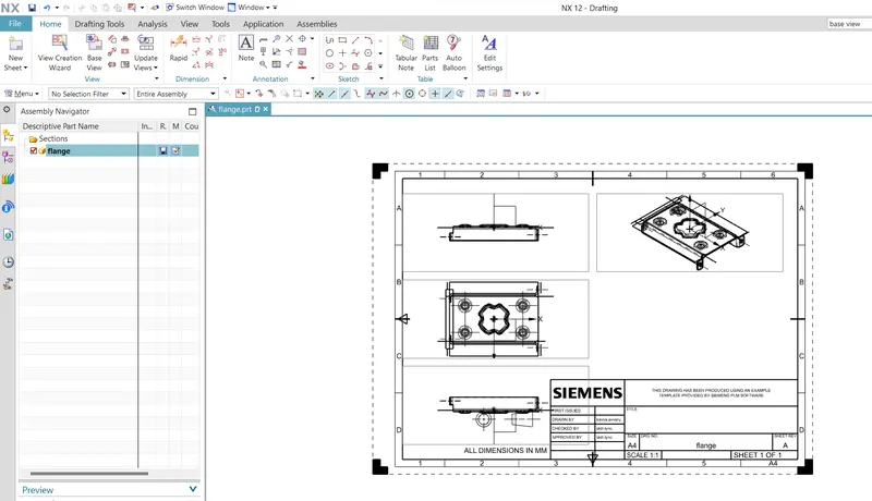
drafting is to represent the model in 2D form or on the paper with several views like some isometric view,top view,side view,which describes the geometry,factors,and the application of the model.
12. rebend:-
the feature is used to rebend the sheetmetal after applying the extra features on the unbend sheetmetal model like hole dimple ,beads etc., the rebendimng after applying the extra features.
creating a casing by sheetmetal