Photo Realistic Rendering
li* Week 7: Report on Assembly of Chopper Model.
Objective : To perform the assembly, for designed chopper parts .
Introduction: Performing assembly ,for designed parts like ,chassis, engine ,chain,kick stand , front and rear wheel ,front and rear fender , gas tank,oil tank ,front frok .
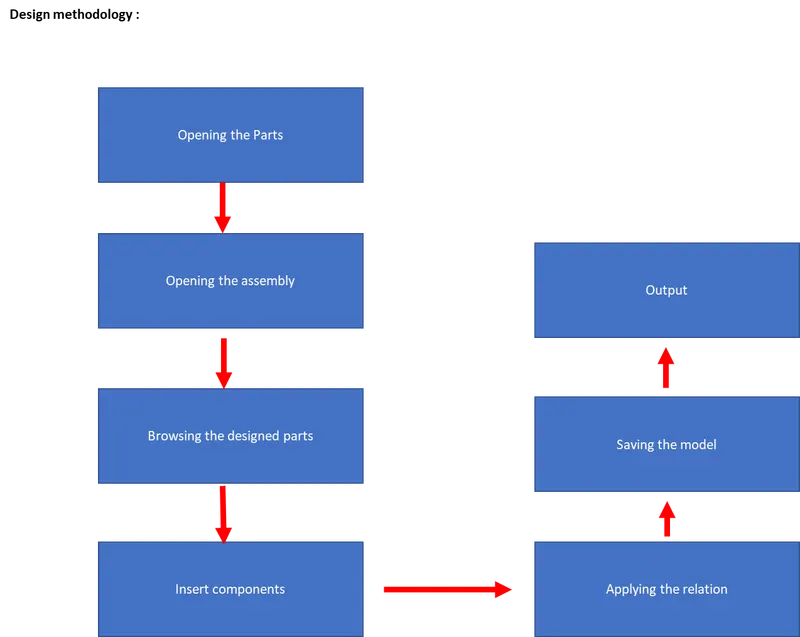
Description
* click to open and select part .
* Now, go to browser and select the required all parts which need to assembled as shown below .
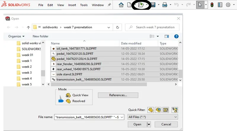
* After opening parts again go to tool bar and select new ,moreover create a assembly file as shown below
.
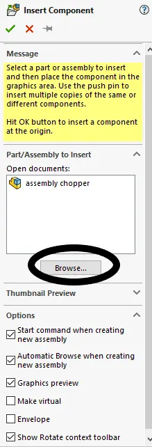
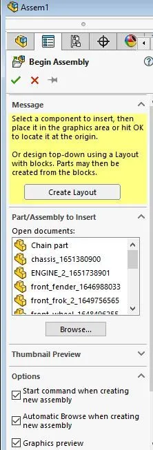
* Furthermore , In assembly toolbar click to insert components and select parts one by one as shown below .
* Before browsing the componenets * After browsing the componenets
* Inserting Chassis :
* Select the chassis part from browser and click ok
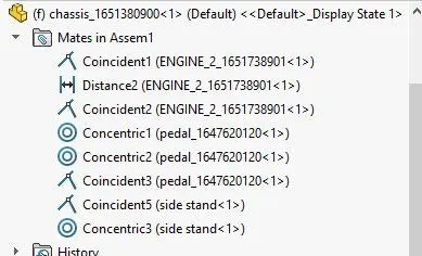
* The relation applied Between engine and chassis:
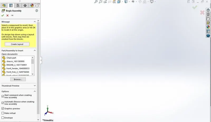
* Before browsing the Chassis
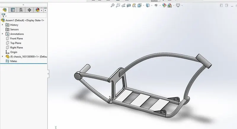
* After browsing the Chassis :
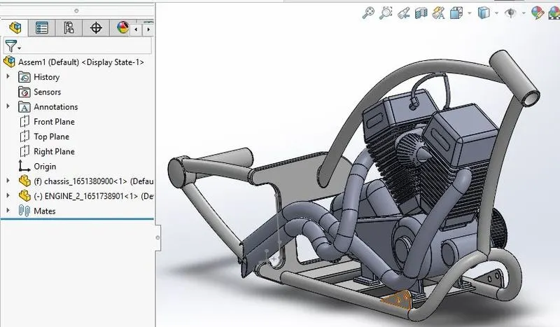
* Inserting the Engine:
* Now, the Engine part from browser and click ok as shown above :
* As the engine is placed to chassis , select the engine surface and chassis surface,then right click to make coincidence .
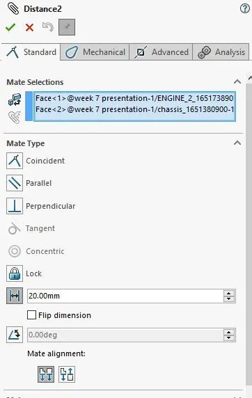
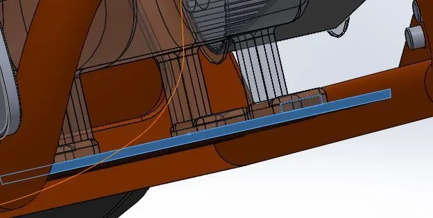
* Now again select the vertical surface of chassis and engine ,moreover click to distace option and give the distance 20mm .
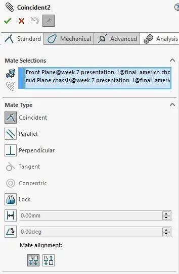
* Then select the front plane of engine part and front plane of Chassis to make coincidence and to make fully defined .
* Further if any correction are required for the parts are to be done.
* The relation applied Between Engine and chassis:
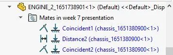
* Select the Bottom surface of engine and a surface of chassis to make coincidence.
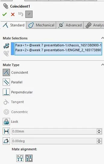
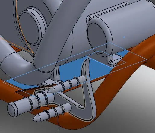
* Select the surface of engine and chassis click to distance option giving it to 20mm distace to be placed.
* Select the front plane of engine and front plane of chassis to make coincidence so that the engine gets attched with chassis as shown below .
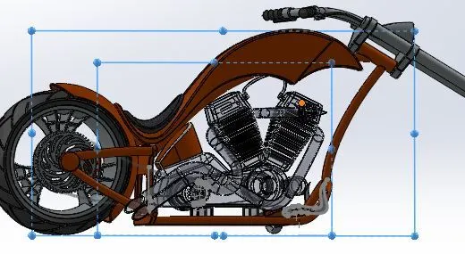
* Before browsing the Engine
* After browsing the Engine and applying relation
* Inserting the Pedal:
* Select the pedal part from browser and click ok
* The relation applied Between Pedal and chassis:
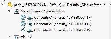
* After inserting the pedal ,as shown above and applying the relation with respect to chassis
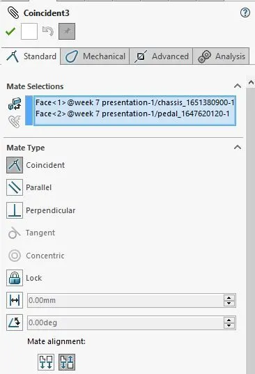
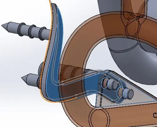
* Applying the mates , Selecting circular face of pedal to circular face of chassis applying the coincidence relation .
* The highlighted part indicates the selection .
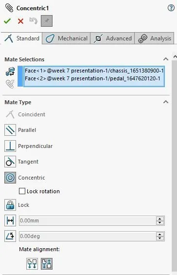
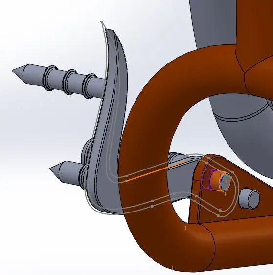
* Again Selecting other circular face of pedal to circular face of chassis applying the coincidence relation .
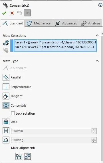
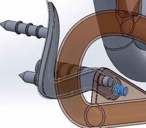
*Selecting the surface of pedal and a chassis to make coincidence so that the pedal moves according to the chassis .
* Before Inserting the Pedal:
* After Inserting the Pedal :
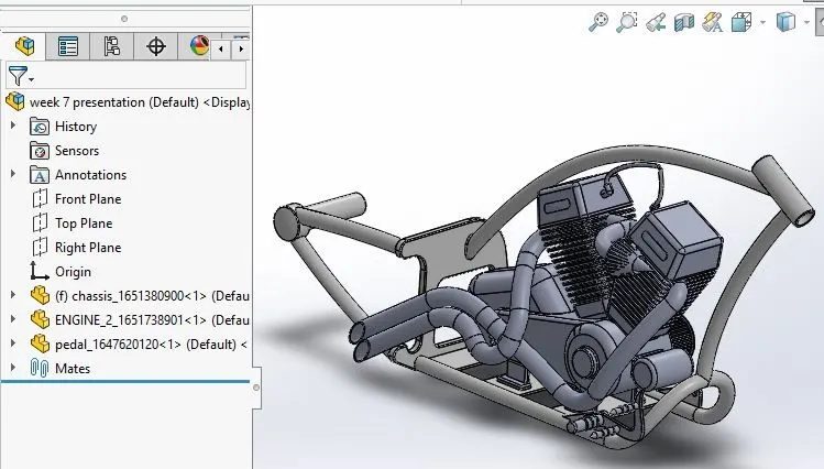
* Mirroring the pedal in opposite side.
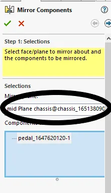
* In assembly tool bar click to linear pattern and select mirror then selecting the required plane which need to be mirrored and click ok as shown below .
* Next to select the center to opposite icon to placed extactly opposite to chassis
* adding the suffix as required and click ok as shown below .
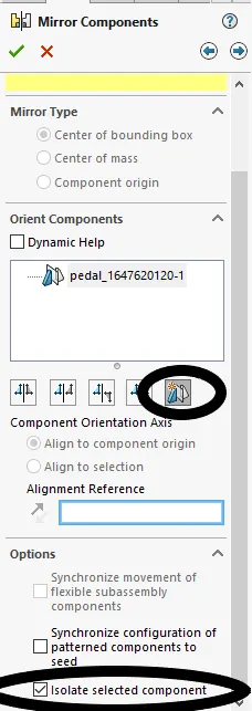
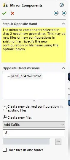
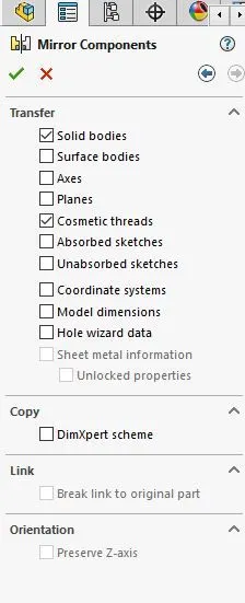
* Before Mirroring the pedal :
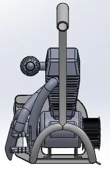
* After Mirroring the pedal :
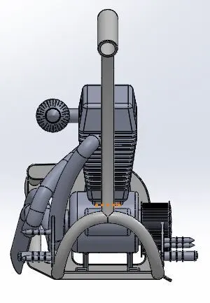
* Inserting the kick stand :
* In assembly toolbar select insert components and select the kick stand file ,click browse and ok as shown above.
* The relation applied Between kick stand and chassis:
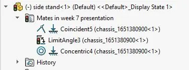
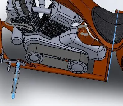
* From assembly go to mates amd select the middel plane of stand and a parallel surface to make the stand perpendicular to chassis .
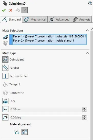
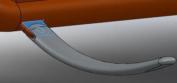
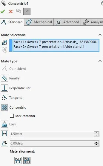
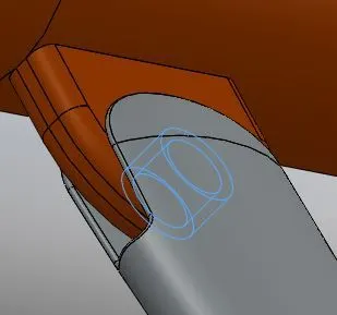
* Before Inserting the kick stand :
* After Inserting the kick stand :
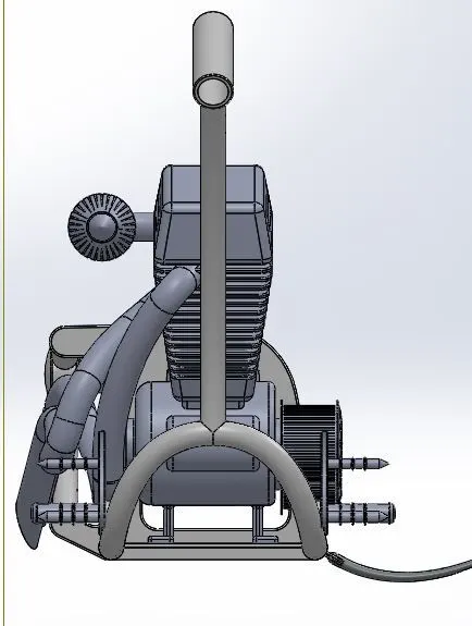
* kick stand before applying to particular direction :
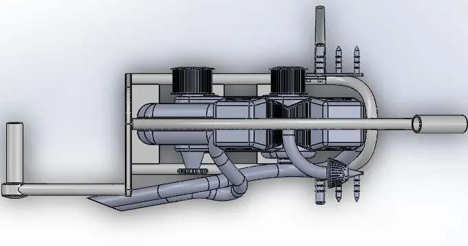
* kick stand after applying to particular direction :
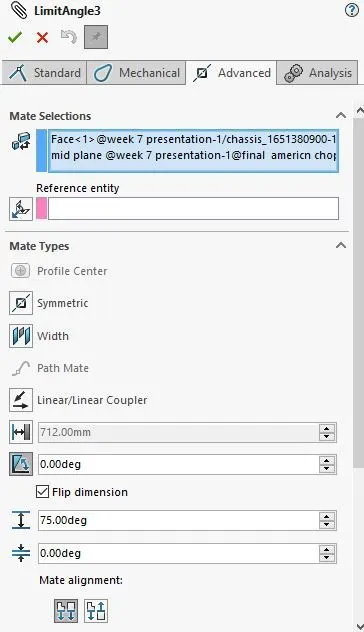
* And then ,setting the limit angle to 0-75 degree so that the stand moves in particular direction .
* Inserting the Transimission belt :
* Using above option select the trans mission belt and insert.
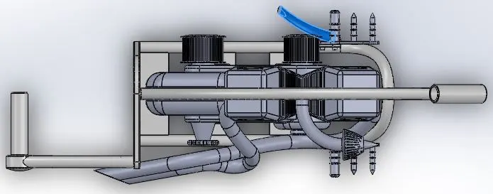
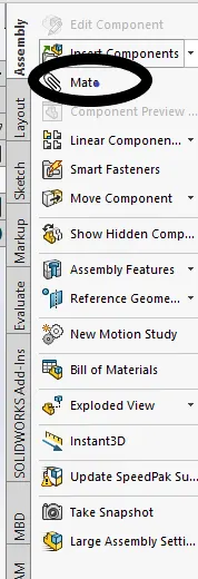
* To place the transmission belt to engine ,Width option from mates ,assembly .
* select the required two edges from tranmisson belt and the two edges of engine .
* select the circular surface of transmission belt and from engine making it to coincidnce
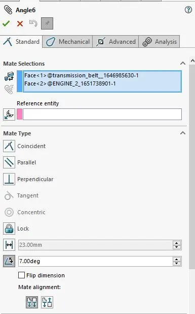
*And for lower part transmission belt surface and surface of engine making it to parallel and giving an angle of 7 degree as shown below .
* Perfroming of Mates are shown below.
* The mates applied Transmission belt and Engine :
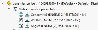
* Applying of width to transmisssion belt 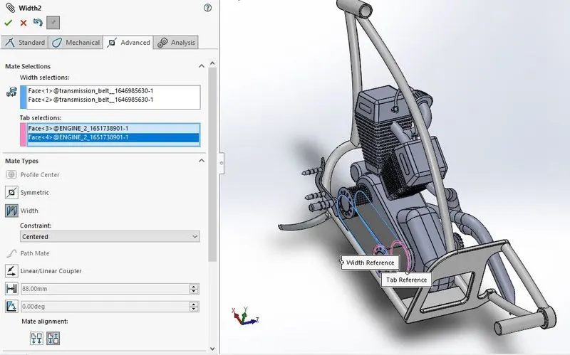
* Applying Parallel relation to other part of transmission belt with 7 degree angle
* Assembly before applying transmission belt :
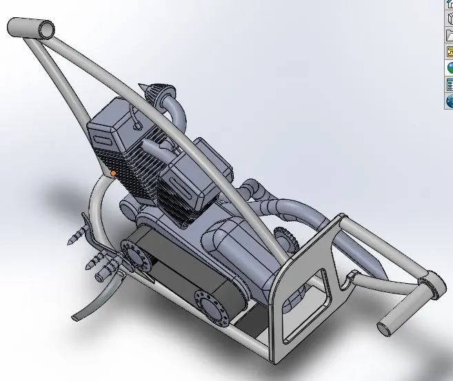
* The assembly after applying 7 degree angle :
* Inserting oil tank :
* Performing the same operation using insert components.
* The mates applied oil tank and Chassis :
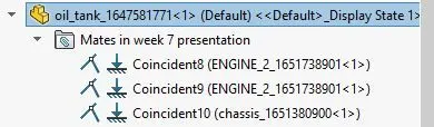
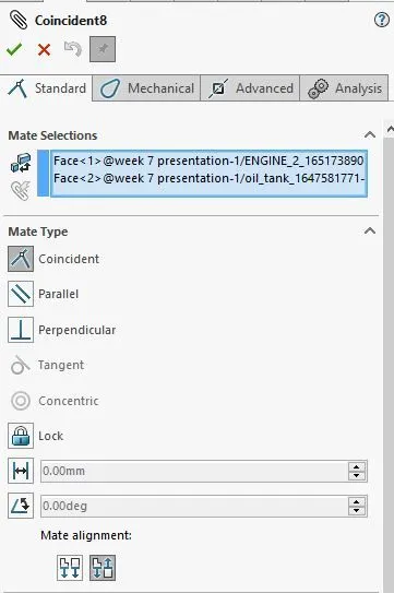
* To provide relations select the bottom plane of oil tank and top surface of engine to make coincidence.
* The highlighted part are the selected part.
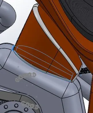
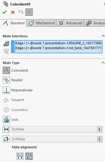
* select the edge of oil tank and edge of top surface to make coincidendce .
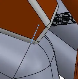
* Select the right palne of oil tank and right palne of chassis so that the oil tanks stays with the chassis.
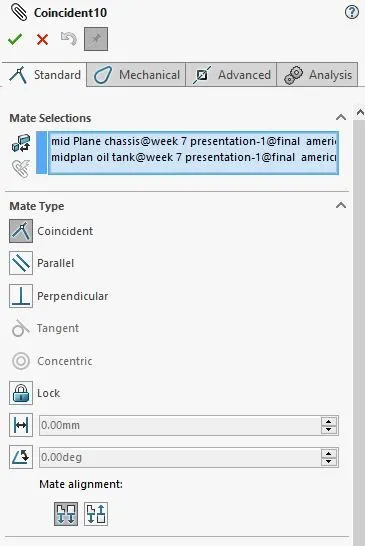
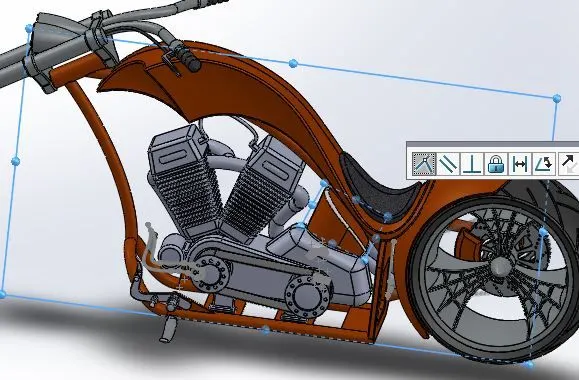
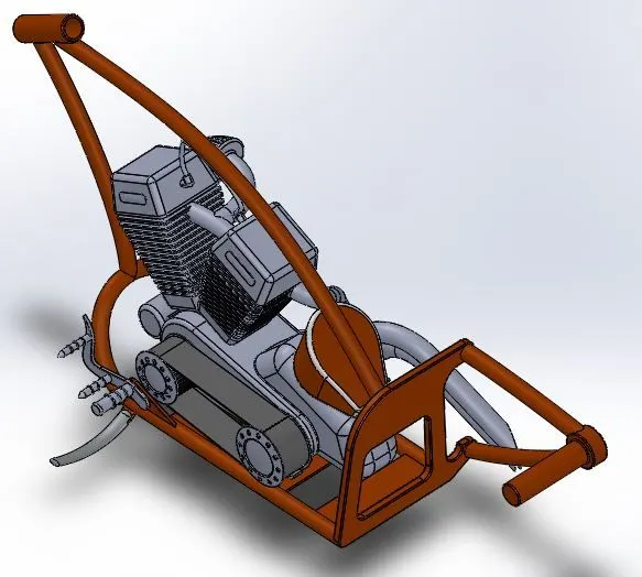
* Assembly before performing oil tank mates :
* Assembly After performing oil tank mates :
* Inserting Rear Wheel :
* Performing the same operation using insert components.
* The mates applied Rear wheel and Chassis :
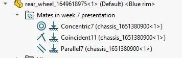
* Place the rear wheel according to chassis .
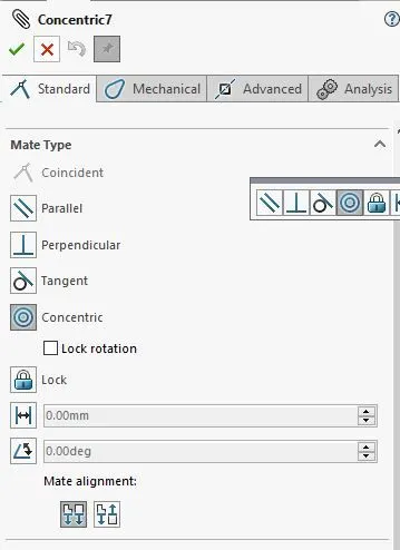
* To perfrom relation select Circular region of rear wheel and Circular region chassis and make to coincidence .
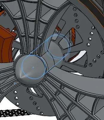
* select the surface of rear wheel and chassis to make coincidence .
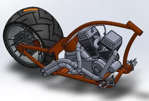
* Assembly before performing Rear Wheel mates :
* Assembly After performing Rear Wheel mates :
* Inserting rear fender :
* Performing the same operation using insert components.
* The mates applied Rear fender and Chassis :
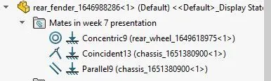
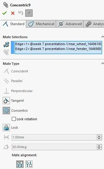
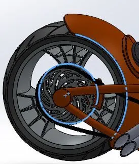
* Select the circular edge and circular surface of rear wheel and make it to coincicdence .
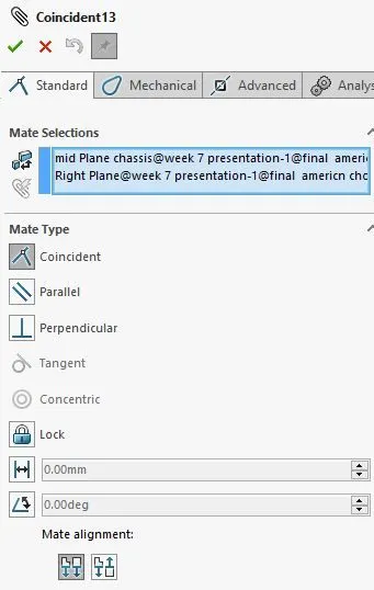
* To perfrom relation select mid plane of rear wheel and right plane rear wheel fender and make to coincidence .select the surface of rear wheel and chassis to make coincidence .
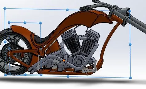
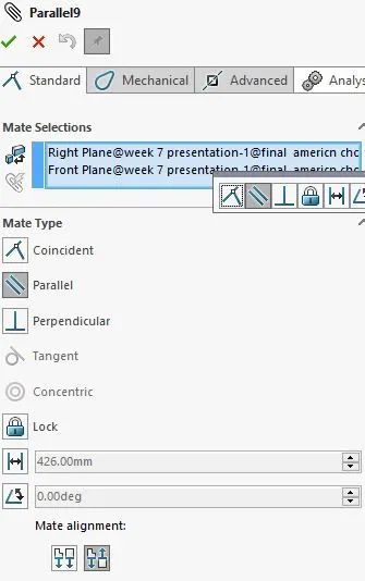
* For Rotation purpose the parallel option are required ,so selet the right plane of rear wheel and the front plane of chassis .
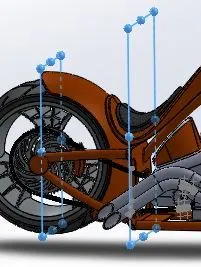
* Assembly before performing Rear fender mates :
* Assembly After performing Rear fender mates :
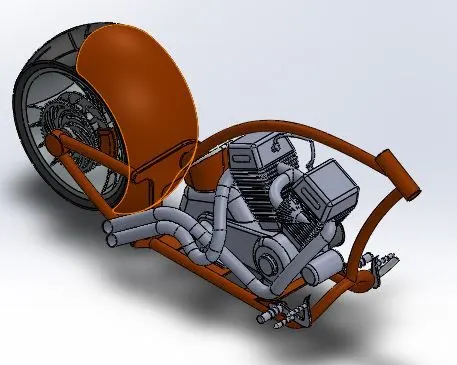
* Inserting the Gas Tank :
* Performing the same operation using insert components.
* To perform the mate option ,select the front plane of gas tank and plane 2 of chassis and make it coincidence .
* Same select the bottom plane and bottom plane to make coincidence.
* The mates applied Gas tank and Chassis :
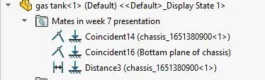
* Inorder to define fully the gas tank , select the front palne of gas tank and plane 2 which fits perfectly to coincident .
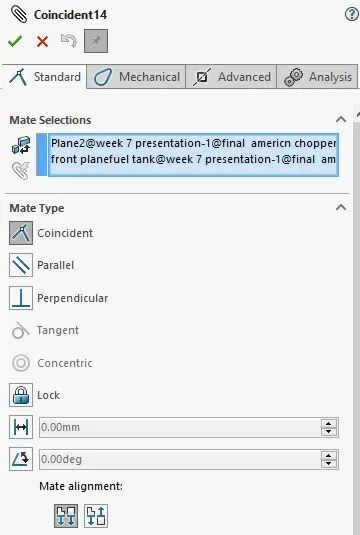
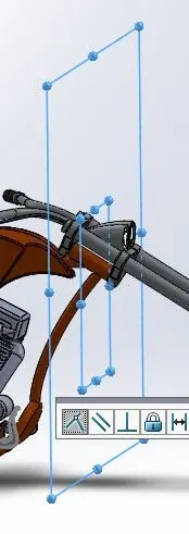
* Furthurmore ,applying for bottom plane of both gas tank and chassis
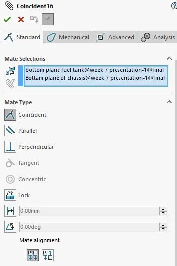
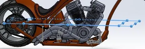
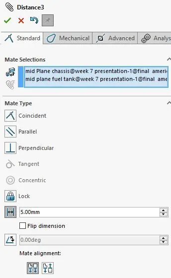
* Performing distance .
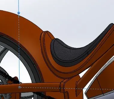
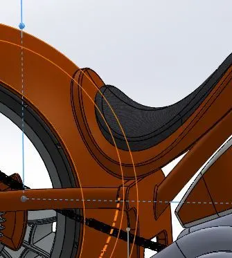
* If the distance is not applied the seat doesn't sits properly as it collapse with rear fender .
* If the distance is not mentioned ,then the part are shown below
* If the distance is applied to 5 mm then the part are shown below.
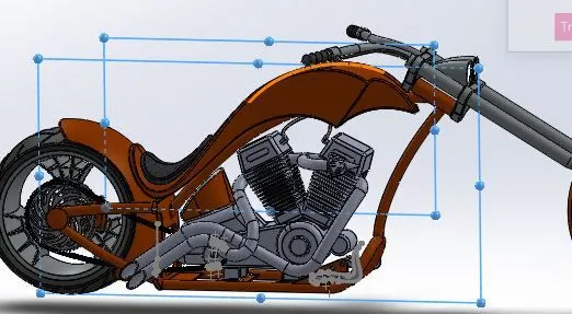
* Assembly before performing Gas tank mates :
* Assembly After performing Gas tank mates :
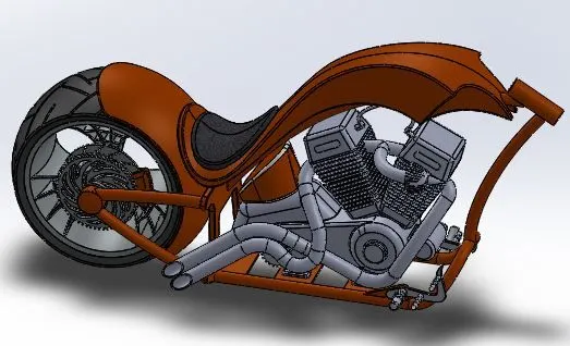
* Inserting the Front frok :
* Performing the same operation using insert components and rotating according to appropriate anglle .
* After insert the model ,mates need to be done and selecting the face of frok and face of chassis to make coincidence .
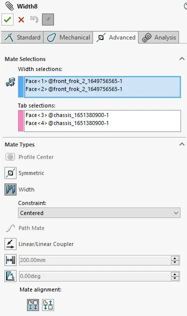
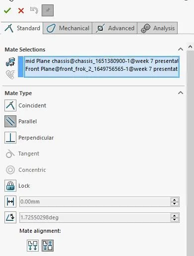
* Performing width option to place frok to chassis
* From mates select advance option and click width ,finally select the required surfaces to be fixed.
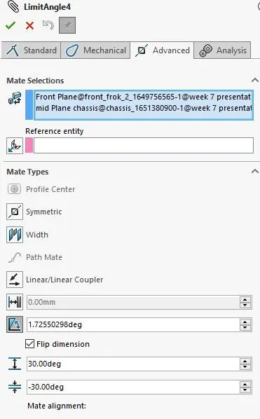
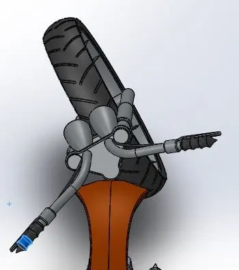
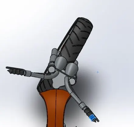
* Provide a limit angle from (-30 , +30) degree so that the frok rotates only in metioned direction .
* select the front plane of frok and front plane of wheel to make parallel to bring back to 180 degree when required.
* The mates applied for Front frok and Chassis :
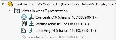
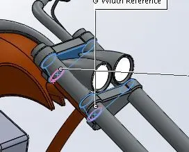
* Applying width to front frok with respect to chassis:
* Select the surfaces between the front frok and chassis ,click ok as shown below :
* Applying limit angle :
* Mates as done for parallel :
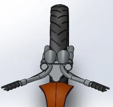
* Assembly before performing Front frok mates :
* Assembly After performing Front frok mates :
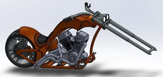
* Inserting the Front Wheel :
* Go to insert componenets and browse front wheel from browser .
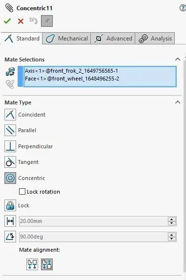
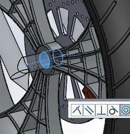
* Now ,Rotate it to appropriate direction and select the circular surface of front wheel and surface of frok to make coincidence as show below
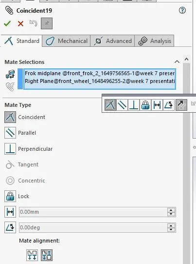
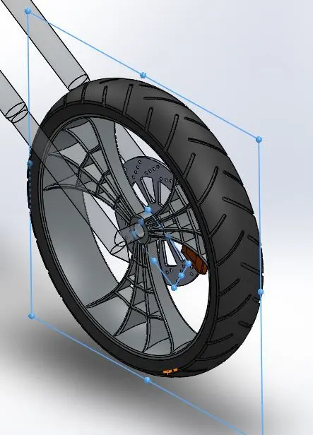
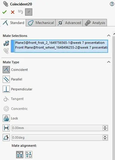
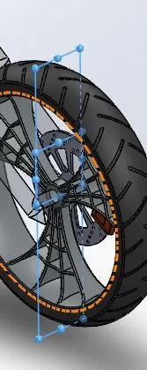
* Select the front plane of front wheel and plane created with respect to front frok to make coincidence which makes fully defined.
* The mates applied for Front frok and Front wheel :
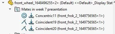
* Performing coincidence to front wheel and front frok .
* Assembly before performing Front Wheel mates :
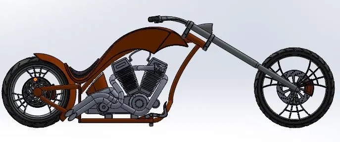
* Assembly After performing Front Wheel mates :
* Inserting front fender :
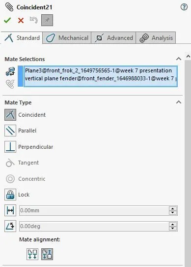
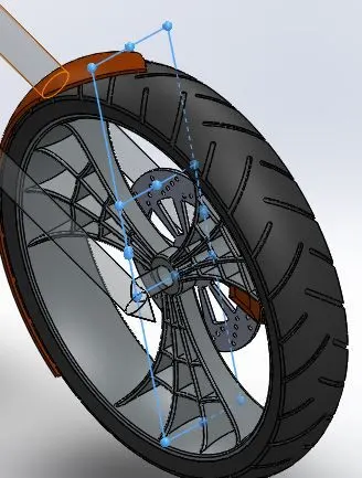
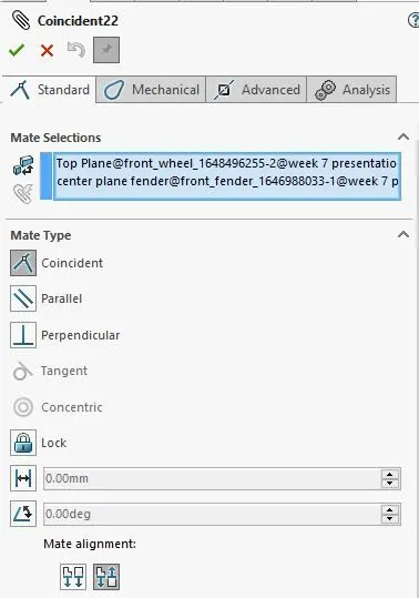
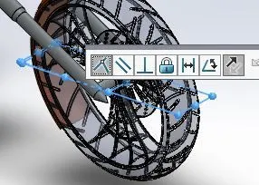
* Grab the fender fro insert components ,rotate to particular direction with respect to front wheel .
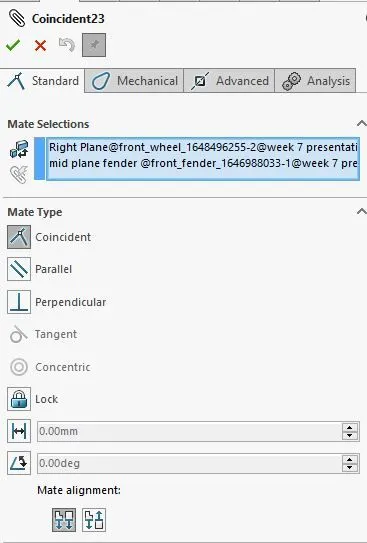
* Matting the faces of fender and front wheel by selecting the front face of fender and front face of wheel ,right face of fender and right face of wheel etc.
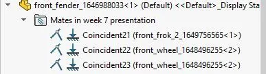
* The mates applied for Front fender and Front wheel :
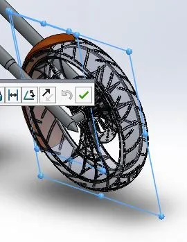
* Assembly before performing Front Fender mates :
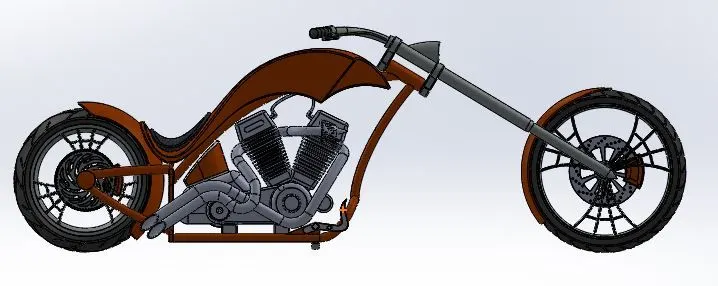
* Assembly After performing Front Fender mates :
* Inserting Chain :
*Insert chain part from assembly toolbar by browsing .
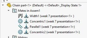
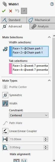
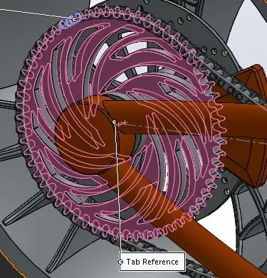
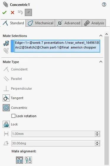
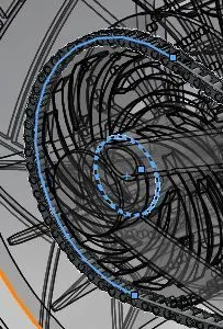
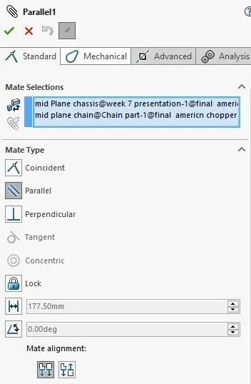
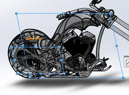
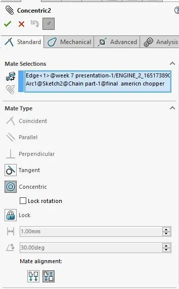
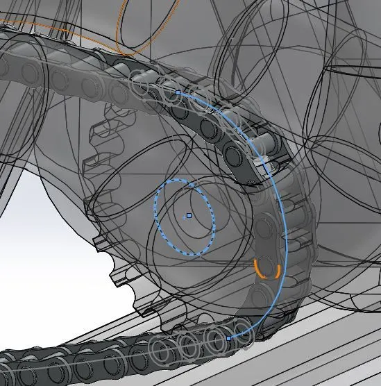
* Performing width option from chain to rear wheel ,select the two parts and click ok as shown below .
* The mates applied for Chain and Rear wheel :
* Assembly before performing chain mates :
* Assembly After performing Front Fender mates :
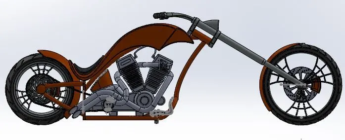
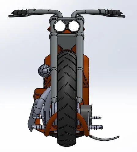
* Front veiw :
* Side veiw :
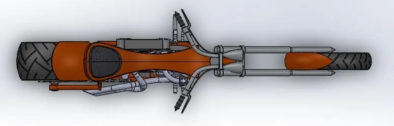
* Top Veiw :
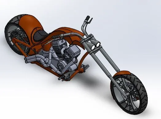
* Isometric veiw .
Week 7: Photo Realistic Rendering
Aim : To perform rendering for above assembled model .
Introduction : Applying the realistic rendering with appropriate environment ,declas ,light and camera with mentioned veiws .
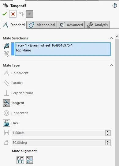
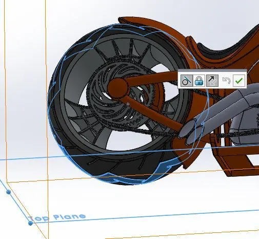
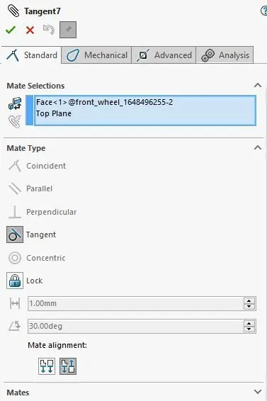
* Berfore Perfroming Rendering , making the tangent by select the top plane of assembly and surface of rear wheel by floating the model .
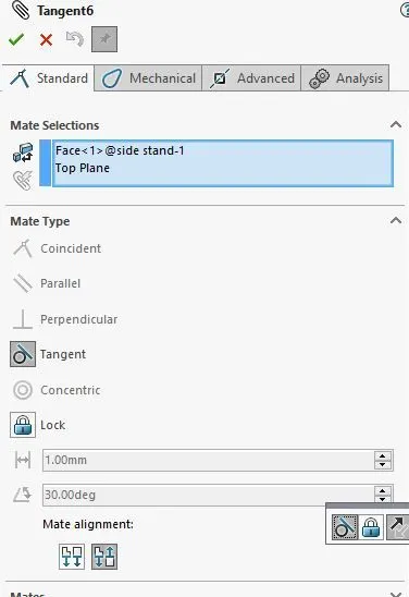
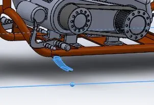
*Then ,select the side stand face and a top plane to make tangent
*moreover the front wheel face and top plane.
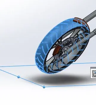
* Here all the faces of kick stand,rear and front wheel are touching the top plane equally are shown below .
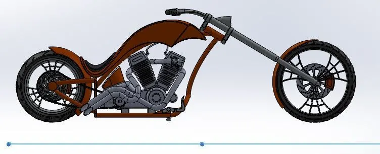
* Assembly before performing mates :
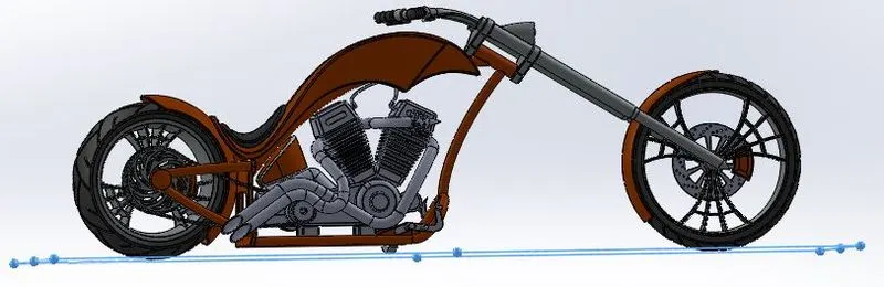
* Assembly After performing mates :
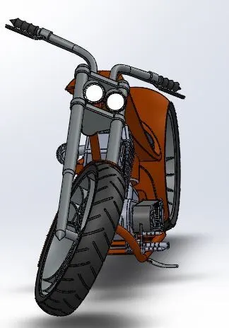
* Performing Decals
* Gas Tank:
* From Assembly ,select the gas tank part and add photo veiw 360 from tools bar .
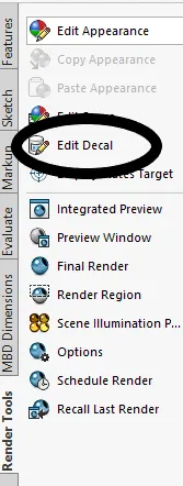
* Now,Select edit decals from render tools and browser the decals images ,fix to particular face .
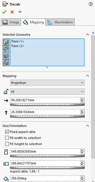
* Then ,select a face of gas tank and place it to particular aixes with XY appropriate dimensions .
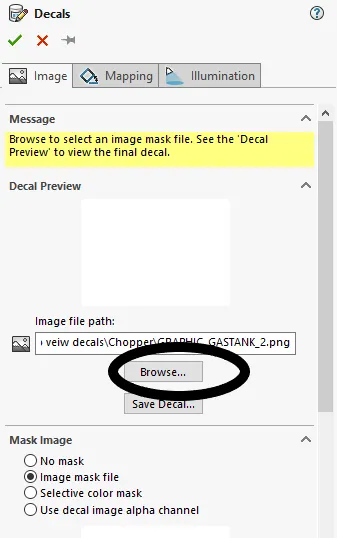
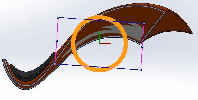
* Click to Mapping and select the required face where decals need to be placed as show below .
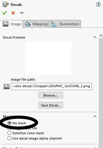
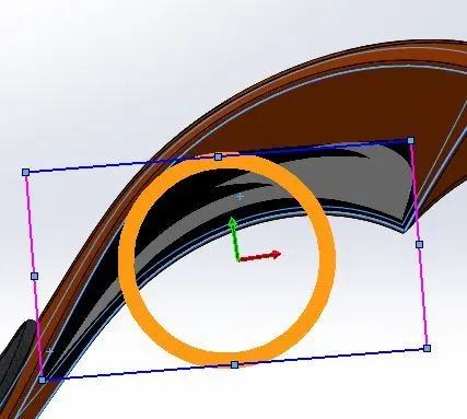
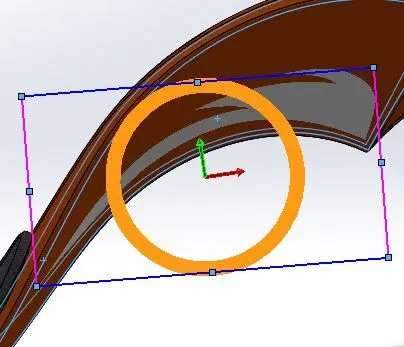
* Then if we use no image option,the decals it looks dark outside of decals as shown below :
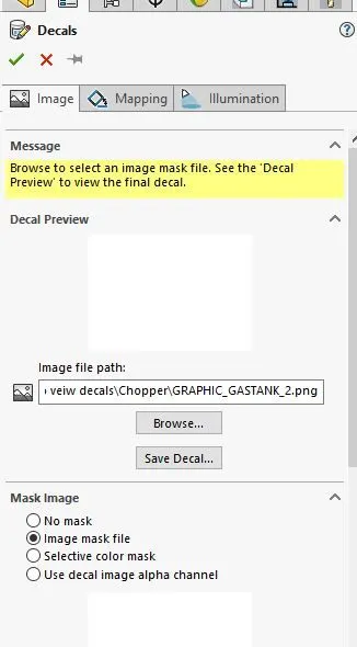
*And if we use Image mask file option,the decals it looks Brighter outside of decals as shown below :
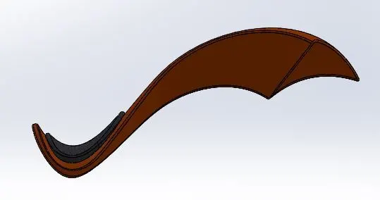
* Gas Tank Before applying decals :
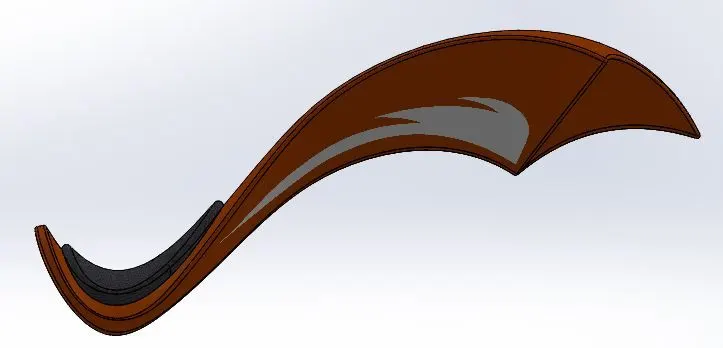
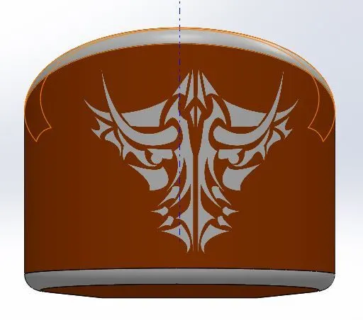
* Gas Tank After applying decals :
* Perfroming the same decals as above :
* Now,Select edit decals from render tools and browser the decals images ,fix to particular face .
* Then ,select a face of gas tank and place it to particular aixes with XY appropriate dimensions .
* Select both faces ,which need to be placed .
*And if we use Image mask file option,the decals it looks Brighter outside of decals as shown below :
* Gas Tank Before applying decals :
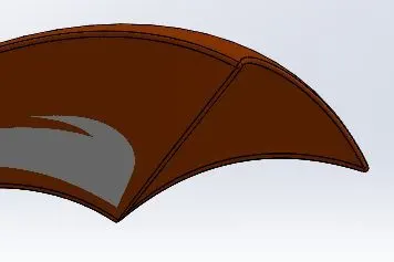
* Gas Tank After applying decals :
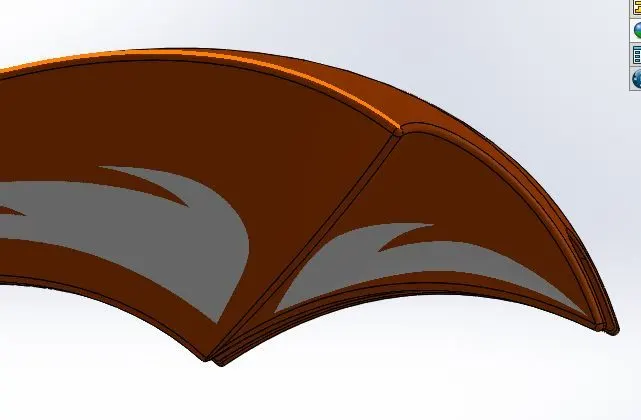
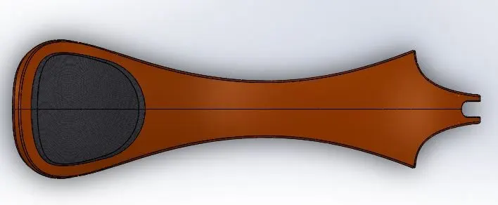
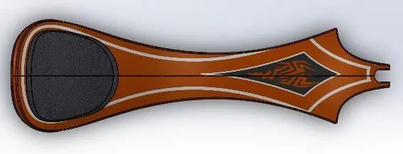
* Applying Decals for Top surface .
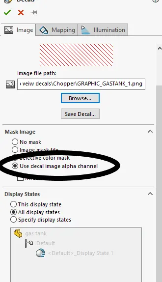
* Go to edit decals from render tools and browse the deacls which is required for gas tank .
* Select the use decal image alpha channel so that it can be placed accordingly .
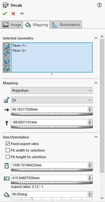
*Now, set the angle to 90degree and place it accordingly as required.
* Select the two surface of top surface .
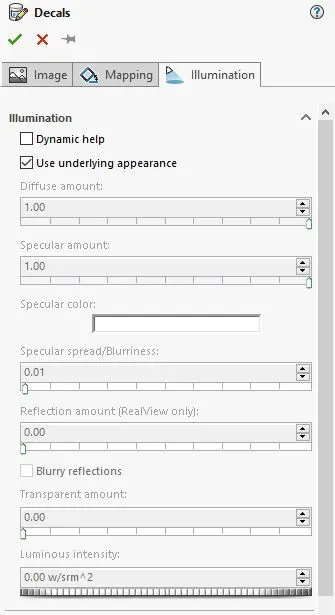
* Gas Tank Before applying decals on top surface :
* Gas Tank After applying decals on top surface :
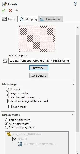
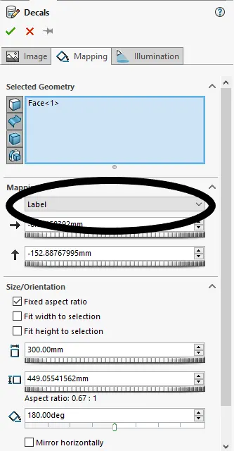
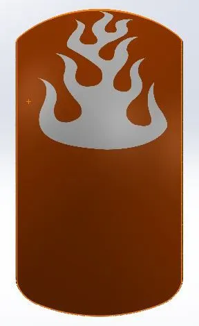
* Applying decals in Rear fender :
* Go to edit decals from render tools and browse the deacls which is required for gas tank .
* Select the use decal image alpha channel so that it can be placed accordingly .
* In mapping select the label option as shown below so that it stays particularly and marking mirror vertically .
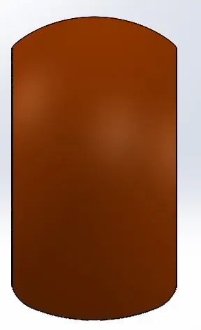
* Before applying decals on Rear fender :
* After applying decals on Rear fender :
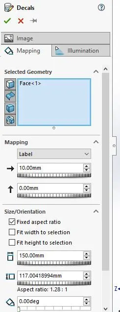
* Applying decals in Oil tank :
* Go to edit decals from render tools and browse the deacls which is required for gas tank .
* Mark the use decal image alpha channel so that it can be placed accordingly .
* In mapping select the label option as shown below so that it stays particularly and marking mirror vertically .
* Before applying decals on oil tank :
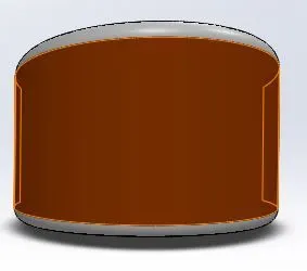
* After applying decals on oil tank :
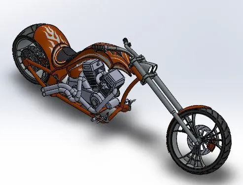
* Isometric veiw :
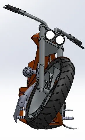
* Front veiw :
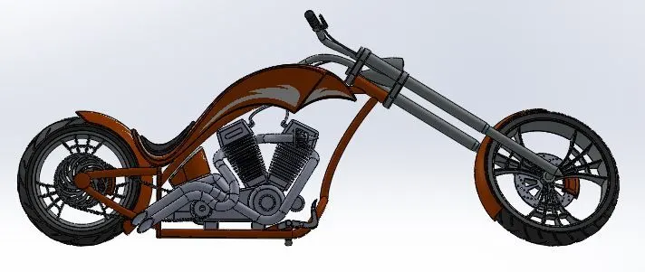
*Right veiw :
* Top Veiw :
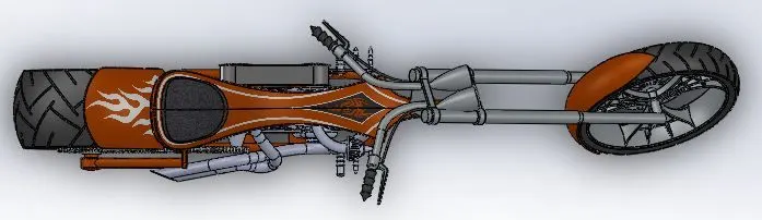
*Camera Setup veiw :
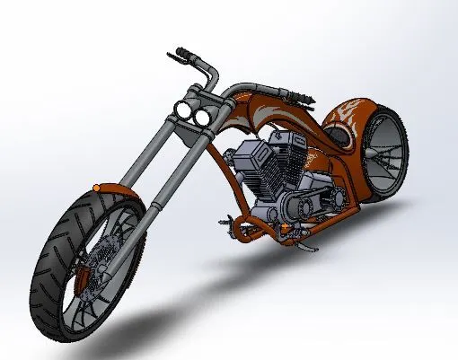
* The model after performing rendering are attached below .
Conclusion : The designing of american chopper can be done with proper assigned dimension and the assembly with perfect selections .