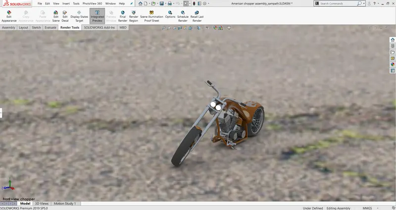
Photo Realistic Rendering
TITLE: MODELLING, ASSEMBLY AND RENDERING OF AN AMERICAN CHOPPER USING SOLIDWORKS
OBJECTIVE:
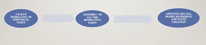
- The main objective of this project is to perform 2-D and 3-D part modelling of individual parts of an ‘American Chopper’.
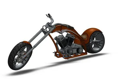
- Further after successfully completing the respective modelling part, I have created an assembly of all the respective parts.
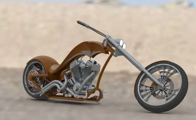
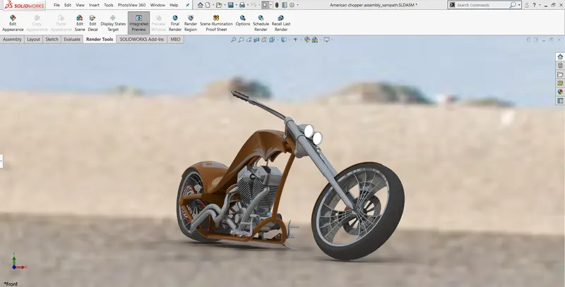
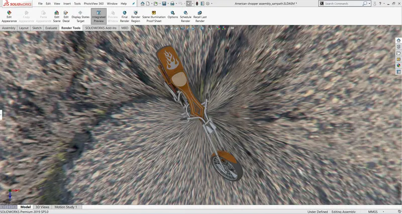
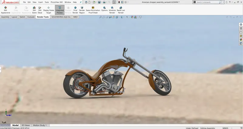
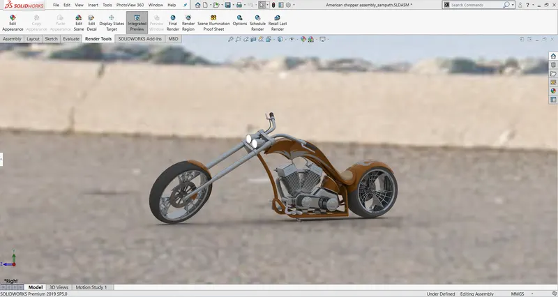
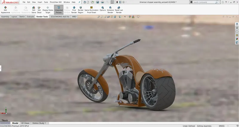
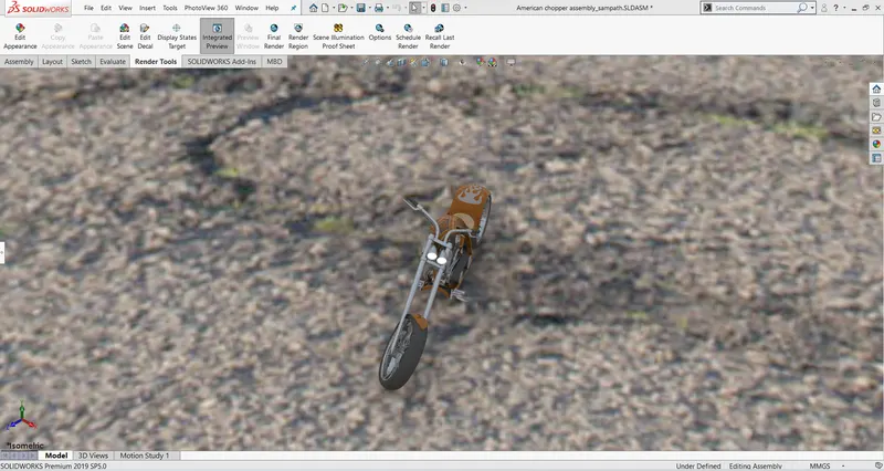
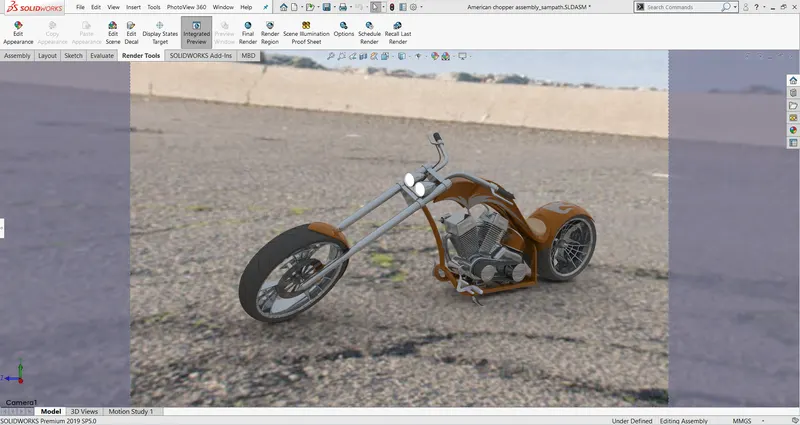
- Once the modelling and assembly is completed, I tried to create renders, background scenes as well, in order to showcase a realistic picturization of the model.
- All the above process are performed using ‘SOLIDWORKS’ software.
INTRODUCTION:
- In this project I have learnt how to model various types parts which are associated with ‘American Chopper’ and also learnt how to assemble then and give them a realistic look using ‘SOLIDWORKS’ software.
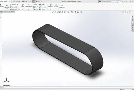
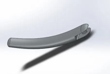
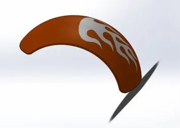
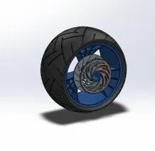
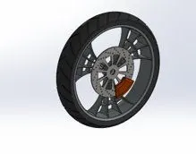
- The main parts that I have modelled here are: 1. Chassis, 2. Engine with Exhaust system, 3. Front and rear wheels with rims, sprockets and brake callipers, 4. Front and rear fenders, 5. Oil tank, 6. Gas Tank, 7. Chain with linkages, 8. Transmission Belt, 9. kick stand, 10. foot pedals
DESIGN APPROACH FLOW CHART:
TOOLS USED WHILE MODELLING AND ASSEMBLY:
- 1. Extrude/Boss : This feature helps us to convert the 2D drawings into 3D models, by giving then the required thickness in third dimension. This step is performed only after creating the 2D sketch.
- 2. Fillet: Fillets are classified as applied features, and as such do not require a sketch to be used. Fillets serve to round off edges and/or corners by adding or removing material, depending on whether the edge is internal or external. It should be noted that fillets of different sizes must be created as separate features.
- 3. Shell: The Shell command allows you to define a wall thickness and automatically hollow the part, while allowing faces to be removed as needed. If no faces are specified to be removed during a Shell feature, the part will be hollow, but this can only be seen by creating a cross section of the part.
- 4. Revolve: This particular feature is used to revolve a particular sketch in a circular/ cylindrical pattern with respect to the axis defined.
- 5. Cut extrude: It is used to cut a particular solid model, by giving desired depth and various other parameters.
- 6. Sweep: This particular tool is used to expand/extrude a particular feature by taking 2 sketches as reference.
- 7. 2-D commands: Commands like line, rectangle, spline, polygon, curves and many more tools are used for 2-d sketching.
- 8. Linear/circular pattern: this command is used to create multiple features by copying the existing feature that we have selected and it instantly based upon our dimensions/parameters given it tries to create similar patterns in a linear and circular patterns.
- 9. Trim: this command is used to trim particular sketches, entities which we wont require will modelling.
- 10. Mirror: this command is used to exactly copy/mirror any particular part with respect to the axis that we have selected.
- 11. Mates: This command is used to join all the parts during assembly with respect to the axis and reference planes of various parts.
- There are many more tools to use but the above mentioned tools are some of the basic tools which helped me a lot during this project.
ASSOCIATED PARTS IN AMERICAN CHOPPER:
TRANSMISSION BELT
KICK STAND
FRONT AND REAR FENDERS
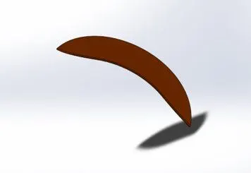
OIL TANK
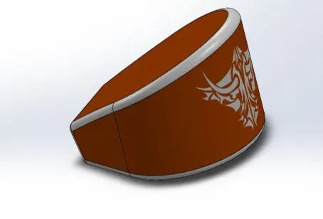
CHAIN LINK
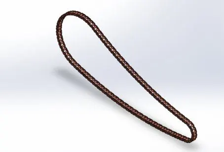
PEDAL
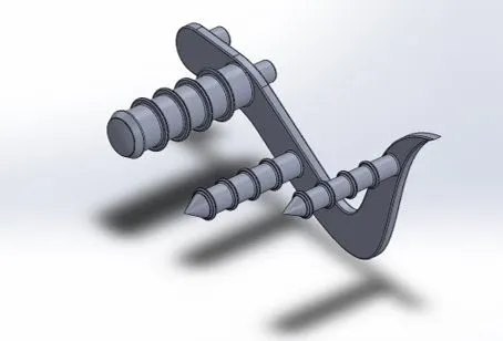
FRONT AND REAR WHEELS
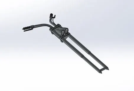
FRONT FORK
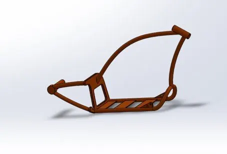
CHASSIS
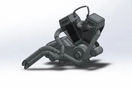
ENGINE WITH EXHAUST SYSTEM
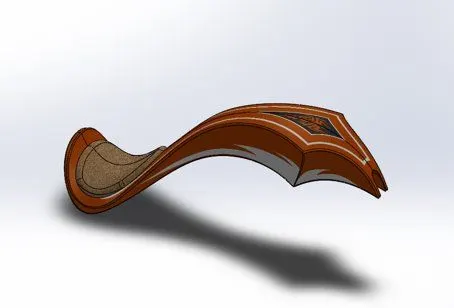
GAS TANK
FINAL ASSEMBLY
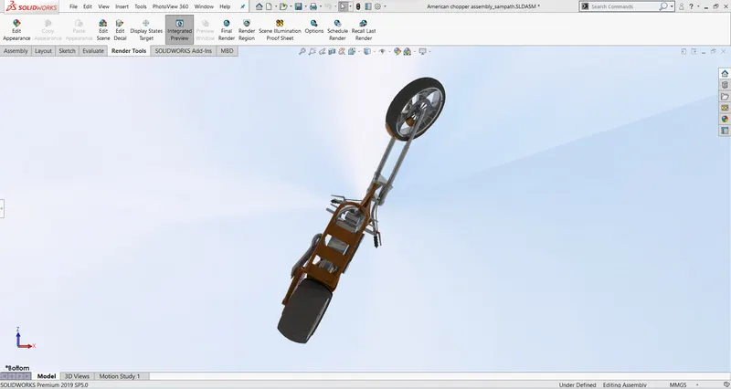
FINAL VIEWS AFTER ADDING DECALS, SCENES AND RENDERS
CONCLUSION:
All the associated parts are modelled as per the blueprints and appropriate dimensions. During Assembly also all the constraints and mates were given properly.
Hence the final American Chopper is modelled successfully using solidworks software.