Advanced Sheet Metal Design Using NX Cad Challenge_2_Box Assembly
TITLE : DESIGN OF BOX ASSEMBLY USING NX-CAD SHEETMETAL APPLICATION
OBJECTIVE: The main objective of this project is to model the sheetmetal part by using sheetmeetal tools and also to model with appropriate dimensions.
INTRODUCTION: Creating fast, accurate flat patterns is the goal of any organization that manufactures products which contain sheet metal parts. NX Sheet Metal provides a set of tools within the NX design environment that allows for simple and fast design of sheet metal parts, dependent on their material and manufacturing process, the most common of which is straight brake sheet metal forming.With NX Sheet Metal, formed and unformed representations of the parts are created closely following the industry workflows and best practices for bending calculations, tooling, and sheet metal features. The value lies in improving quality and reducing cost of sheet metal parts by producing an accurate sheet metal pattern as the correct input for part manufacture, whether internally or to a supplier.
DESIGN METHODOLOGY :
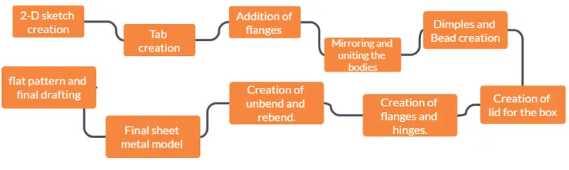
TOOLS USED:
Sketch commands: Line, rectangle, circle, curve, move curve, studio spline are used in making 2-D sketches on the required planes and sheetmetal surfaces.
SheetMetal commands: 1. TAB: This command is used to give thickness and create a solid for the 2-D sketch that we have created.
2. BEND: This command is used to bend edges and corners with the required angles and dimensions of the tab that we have created.
3. FLANGES: This command is another kind of bending tool, which is used to bend edges and give them curved edges with required dimensions.
4. BRAKING CORNERS: This command is used to smoothen the edges of the shapes the we have created.
5. UNBEND: This is used to unbend the sheet metal model and make it a flat pattern.
8. DIMPLE AND BEAD: These commands are used to create a curved hollow features for the sketches that we have selected on sheet metal faces.
9. DRAFTING: drafting, also spelled draughting, also called engineering drawing, graphical representation of structures, machines, and their component parts that communicates the engineering intent of a technical design to the craftsman or worker who makes the product.
10. HEM FLANGE: This is another kind of flange which used near edges to get curved, closed, open loop shapes.
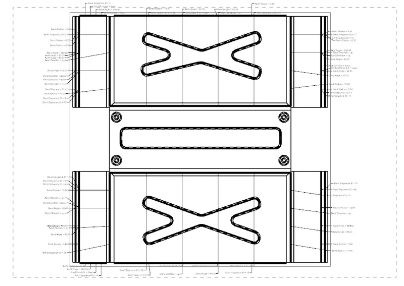
11. FLAT PATTERN: Flat pattern command is used to convert 3-D sheet metal component into 2-D form in siemens NX-CAD.
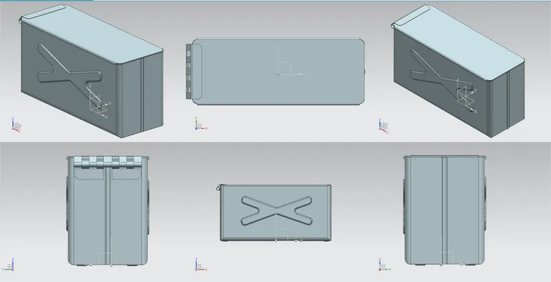
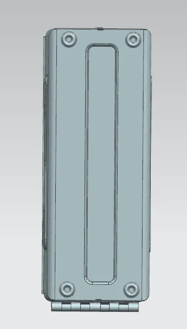
DIFFERENT VIEWS OF BOX ASSEMBLY:
FINAL DRAFT/DRAWING OF THE 3-D SHEET METAL MODEL:
CONCLUSION: Hence the Box assembly is designed with appropriate dimensions using sheet metal operations in NX-CAD.