Advanced Sheet Metal Design Using NX Cad Challenge_6_Bracket
TITLE: BRACKET DESIGN USING NX-CAD SHEETMETAL APPLICATION
OBJECTIVE: The main objective of this project is to model the sheetmetal part (BRACKET) and perform various sheetmetal operations using NX-CAD sheetmetal application to obtain the final output.
INTRODUCTION: In this project intially I have created a sheet metal part instead of directly creating a sheet metal part. Once the sheet metal is created , further sheet metal features and commands are used to generate the final odd shaped enclosure. Bracket is an intermediate component used to fix one thing (like a shelf) to another (like a wall). It may be thought of a kind of fastener, but this is somewhat misleading: actual fasteners like screws are used to connect the bracket to the other parts.In addition to creating a connection between two parts, a bracket may provide support. Some brackets, such as gusset brackets, are designed with a diagonal section that reduces the strain on the bracket and allows it to support heavier loads.Brackets are connecting devices used to join two objects. In architecture, they may be made of wood or stone and used to join walls with features like parapets or eaves. In engineering, however, they are often made of sheet metal and used to support objects like shelving, countertops, flooring, sections of furniture, and mounted televisions.Although there are many types of brackets, they are most commonly L-shaped, with the vertical section of the bracket attached to a wall (or another large upright structure) and the horizontal section attached to a smaller object being fitted to the wall, such as a shelf. Brackets often have holes in them, either threaded or unthreaded, so that screws or other fasteners can be fed through them, but this is not a defining feature of the bracket. Most brackets are functional, with their purpose being to connect and support objects. However, brackets can also be decorative: since brackets are often visible (such as on shelves mounted above eye level) they may have cosmetic features and flourishes, from intricately machined decorative features to gold plating.
DESIGN METHODOLOGY :
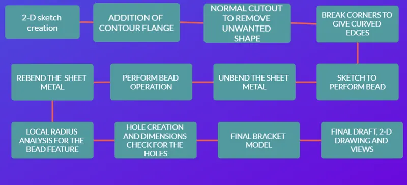
TOOLS USED:
Sketch commands: Line, rectangle, circle, curve, move curve, studio spline are used in making 2-D sketches on the required planes and sheetmetal surfaces.
SheetMetal commands: 1. NORMAL CUTOUT: This command is used to cut the required shape by giving required depth and taking a drawn 2-D sketch/curve as a reference.
2. BEND: This command is used to bend edges and corners with the required angles and dimensions of the tab that we have created.
3. CONTOUR FLANGES: This command is another kind of tool, which is used to create a flange from the sketch/curve drawn.
4. BRAKING CORNERS: This command is used to smoothen the edges of the shapes the we have created.
5. UNBEND: This is used to unbend the sheet metal model and make it a flat pattern.
6. HOLE: This command is used to create a hole on the 3-D model.
7. DIMPLE AND BEAD: These commands are used to create a curved hollow features for the sketches that we have selected on sheet metal faces.
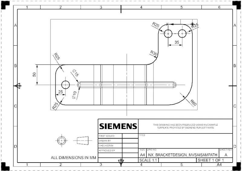
8. DRAFTING: drafting, also spelled draughting, also called engineering drawing, graphical representation of structures, machines, and their component parts that communicates the engineering intent of a technical design to the craftsman or worker who makes the product.
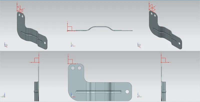
DIFFERENT VIEWS OF BRACKET DESIGN:
FINAL DRAFT/DRAWING OF THE 3-D SHEET METAL MODEL:
CONCLUSION: Hence the Bracket is designed with appropriate dimensions using sheet metal operations in NX-CAD.