Photo Realistic Rendering
MODELING OF AMERICAN CHOPPER IN SOLIDWORKS
Objective
To create fully defined sketches and model parts of chopper in solidworks.
- To create assembly of American Chopper.
- To learn how to apply decals, add and edit materials.
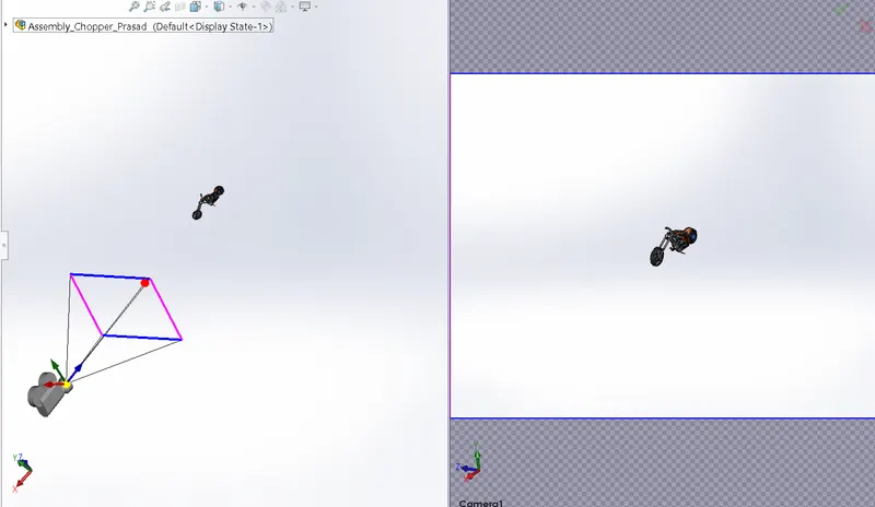
- To understand the application of lights, camera in rendering.
- To create and photo realitistic render of the American chopper using photoview 360 and solidworks visualize.
Design methodology
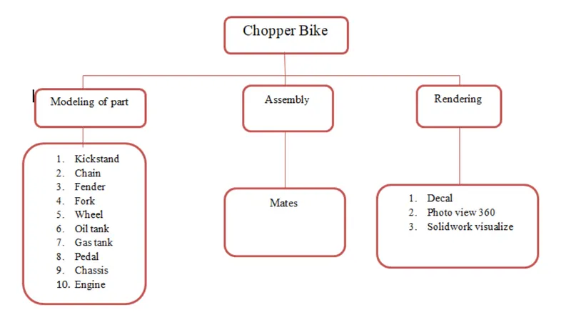
Components Modelled
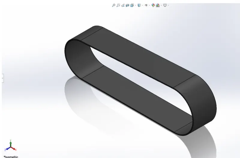
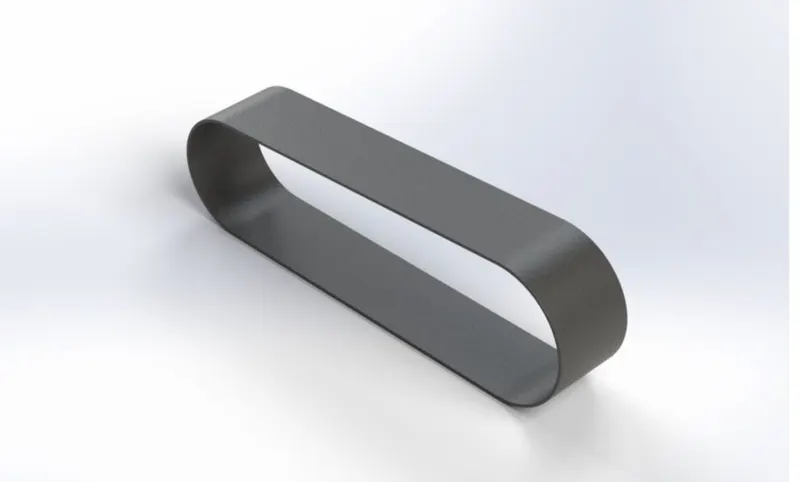
1. Transmission belt:
- Belts is used to transfer power from the engine output shaft to the gear box input shaft. Generally it is made polyster material with the layes or kevlar and sandwish of metallic wires. It's a combination of different elements which is giving it strength to transmit maximum horse power generated form engine to gear box.
- Features used for this model are Offset, fillet & boss Extrude.
Model image
Rendered image
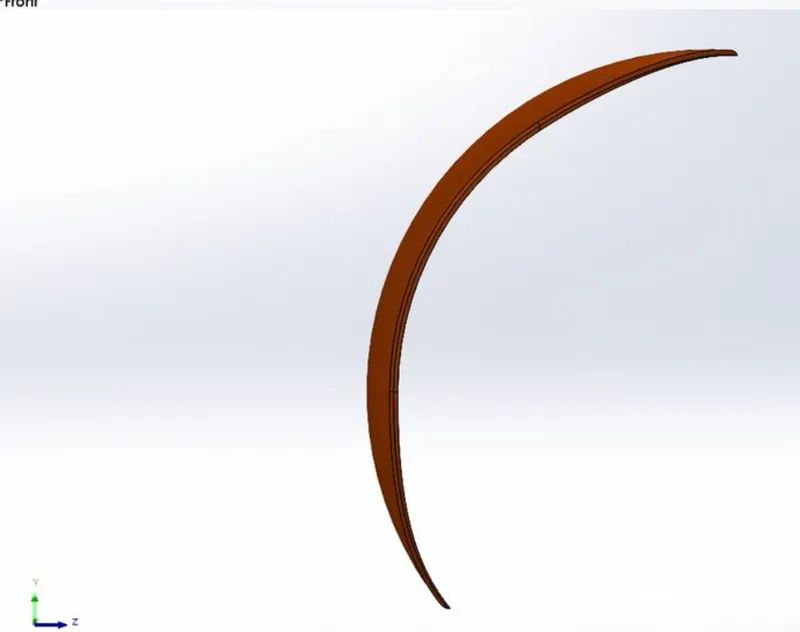
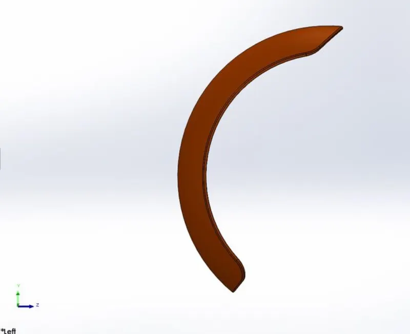
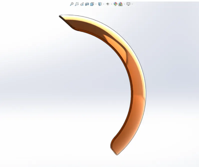
2. Fenders:
- Fender is the American English term for the part of an automobile, motorcycle or other vehicle body that frames a wheel well. Its primary purpose is to prevent sand, mud, rocks, liquids, and other road spray from being thrown into the air by the rotating tire.
- Features used for this model are Revolve, split and fillet
Model image
Rendered image
3. Kickstand:
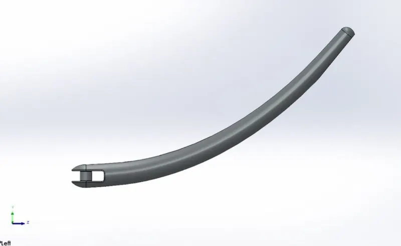
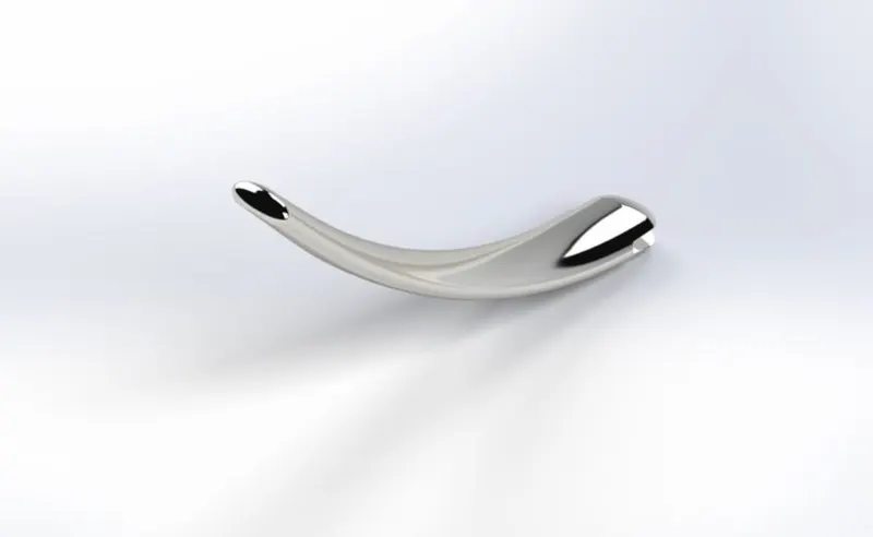
- A kickstand helps support a motorcycle when its parked so it doesnot tip over.
- These kisckstands allow you to position your motorcycle in a parking space and enable you to get on and off your motorcycle safety while its stabilized.
- Features used for this model are Loft and Dome.
Model image
Rendered image
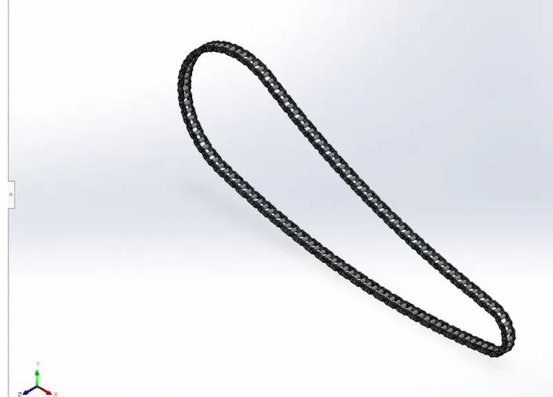
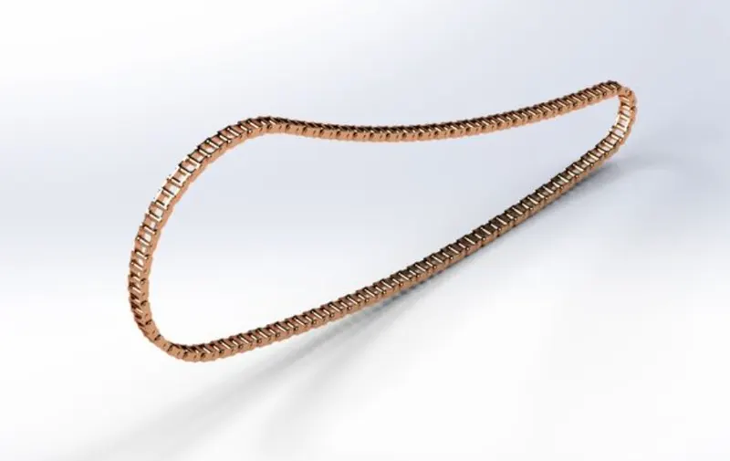
4. Chain:
- Chain is power transmitting unit, it transimit power from Gearbox output shaft to the sprocket attached to the rear wheel. It is constant velocity drive.
- Feature used for this model are curve driven pattern, boss extrude, block.
Model image
Rendered image
5. Oil tank:
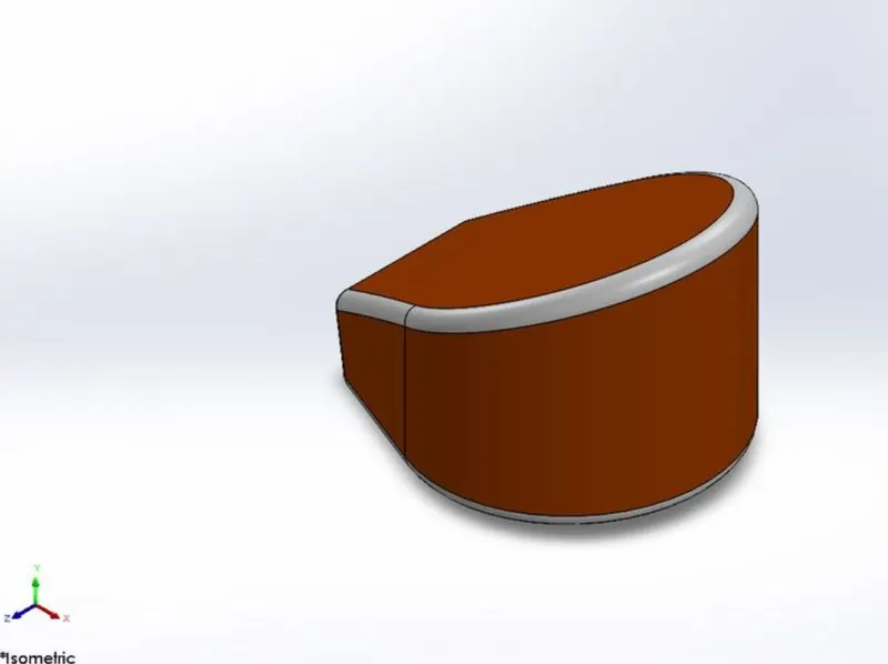
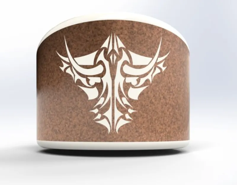
- The oil tank stores the oil which is to be supplied to the engine for cooling& lubrication purposes.
- Features used for this model are Boss extrude, shell, combine , fillet.
Model image
Rendered image
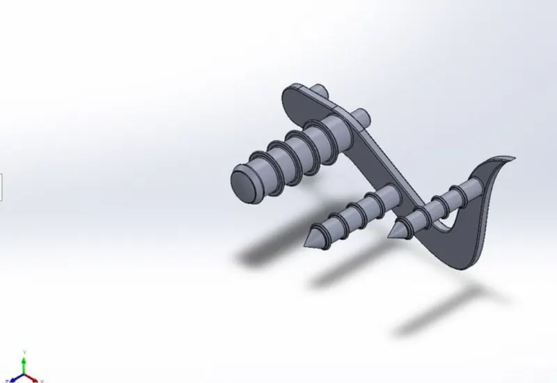
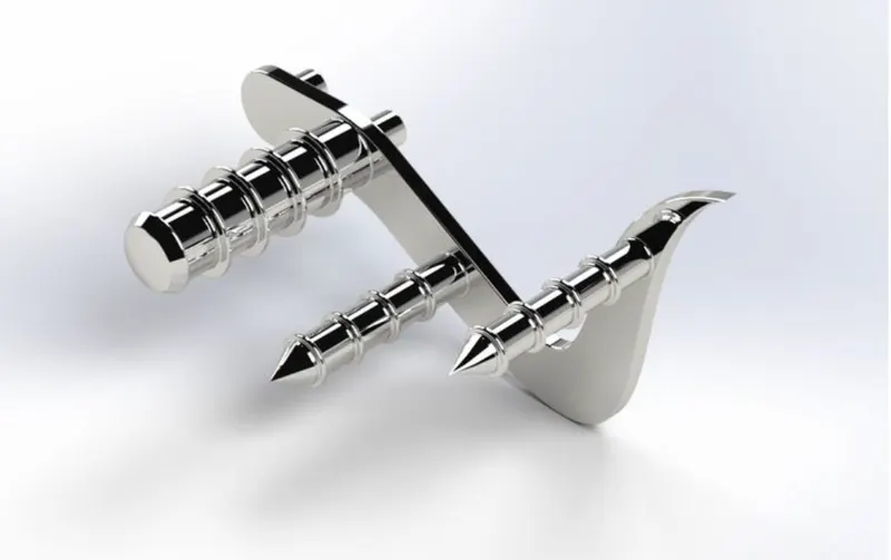
6. Pedal:
- The pedal is a lever controlled with the foot to apply the brakes& also to shift the driving gears. This part is modelled by using commands such as spline, circle.
- Features used for this model are boss extrude, fillet, linear pattern.
Model image
Rendered image
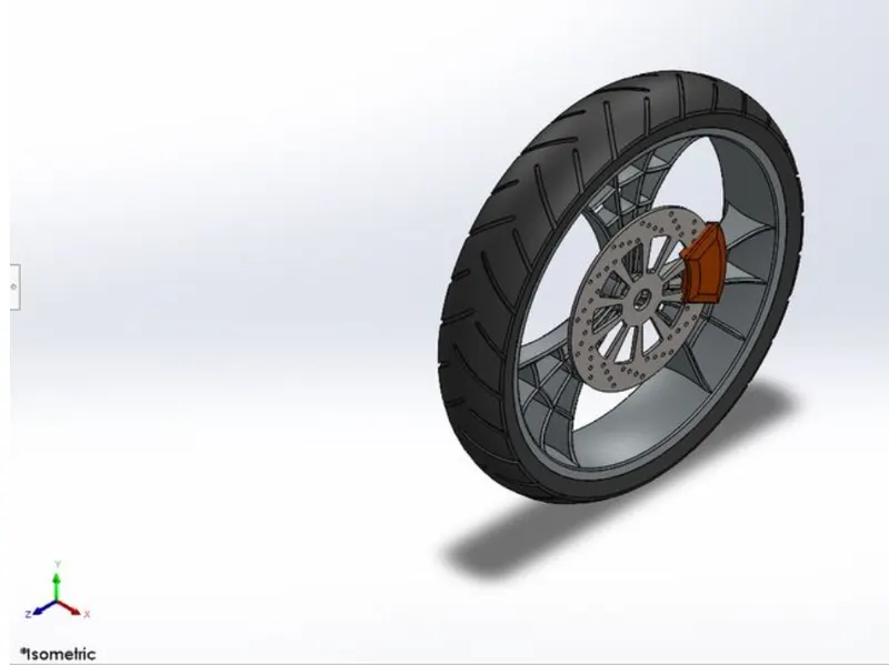
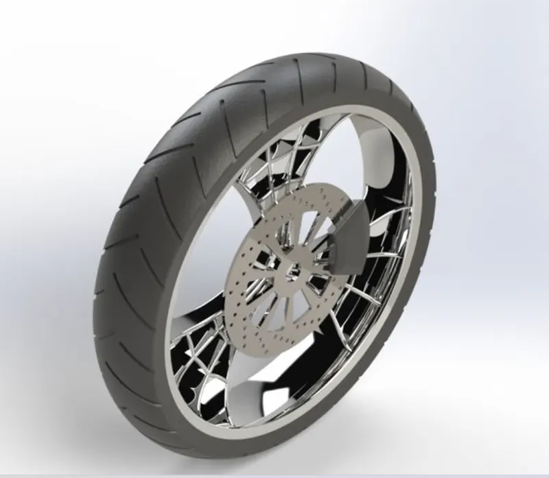
7. Front Wheel:
- The front wheel consists of tire, rotor, caliper, rim and it is designed by using sketch tools such as 3-point Arcs, splines, sketch entites such as offset, mirror& features such as Revolve boss, extrude boss, cut extrude, fillet, champer, mirror and circular pattern.
Model image
Rendered image
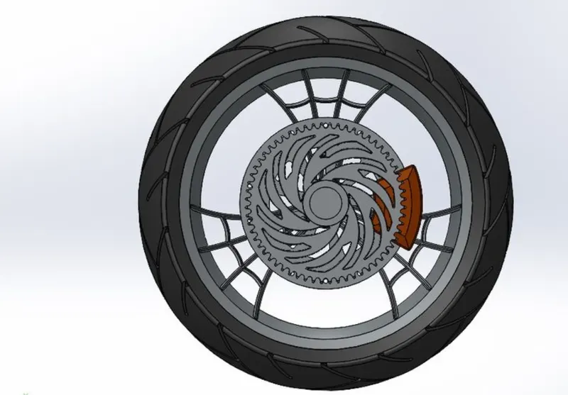
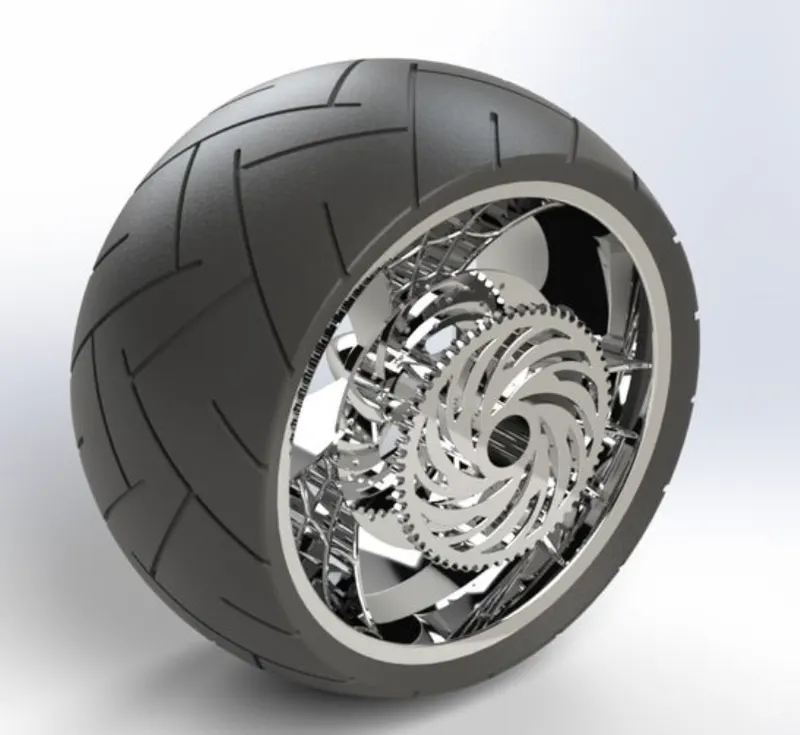
8. Rear wheel:
- The rear wheel consist of tire, rotor, caliper, rim and sprocket. The rear wheel is modelled using similar features that were used while modelling the front wheel.
- But in terms of size, the front wheel diameter diameter (Rim: 640mm, Hub: 350mm) is larger than that of the rear wheel (Rim: 546mm, Hub: 298mm) whereas the width of the rear wheel is larger than the width of the front wheel.
Model image
Rendered image
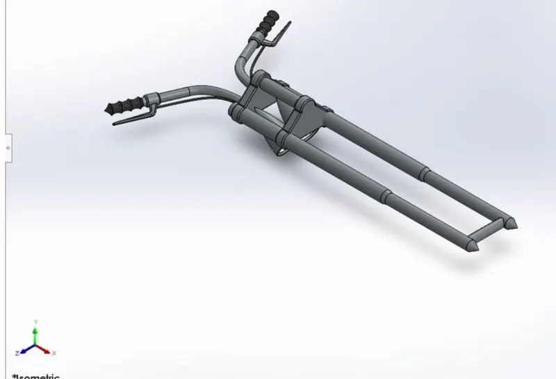
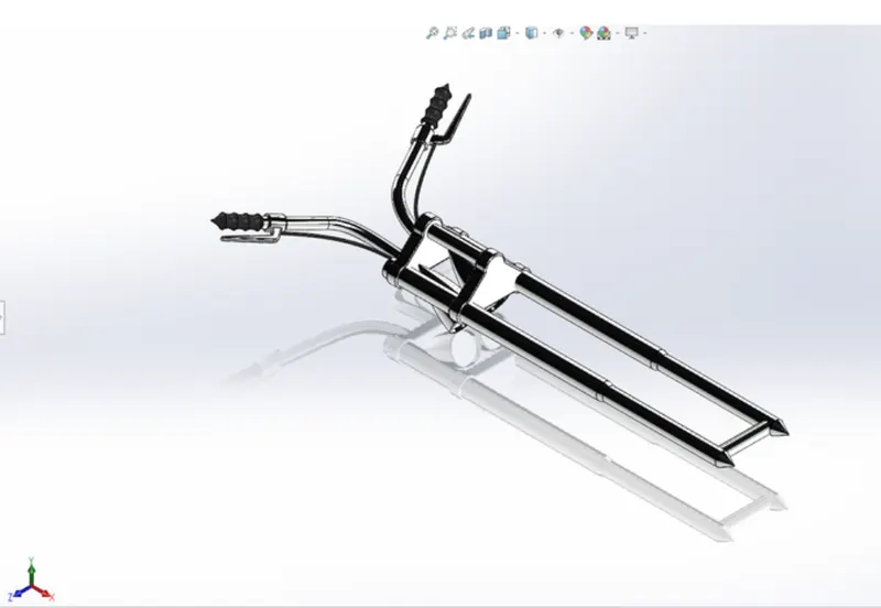
9. Front fork:
- The structure which connects the chassis and the front wheel of the bike. It has various mountings on it like headlights,break wire and levers, shock absorbers etc.
- Features such as boss extrude, Revolve, sweep, projected curves, composite curve, shell, dome, Mirror and Linear pattern were used to model the part.
Model image
Rendered image
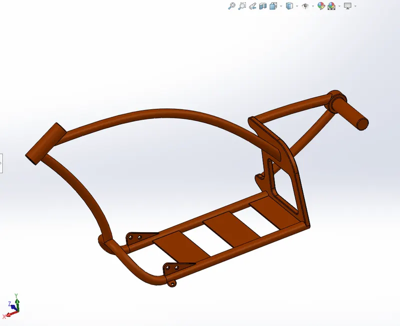
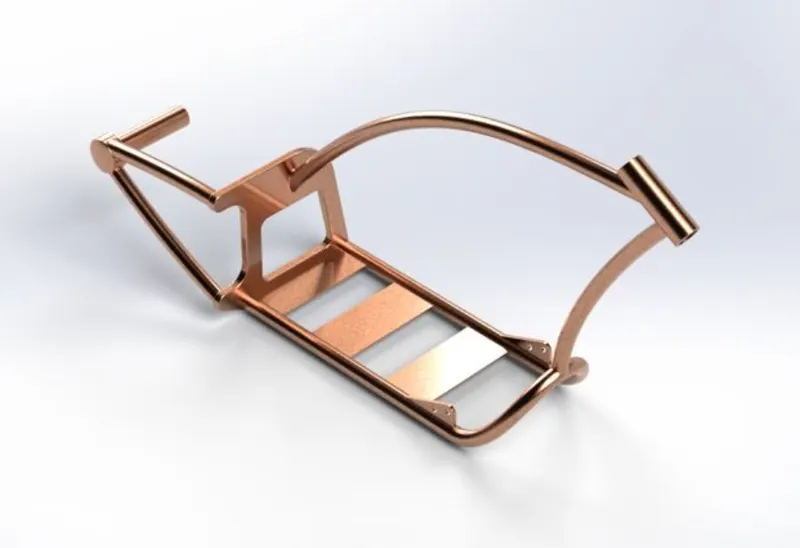
10. Chassis:
- Much like a human spine and the supporting skeleton, a motorcycle chassis holds everything together- from the engine, suspension, wheels, fuel tank, handlebars, seat, airbox etc.
- Features used such as Boss extrude,revolve, sweep, mirror, fillet, champer and projected curves were used to generate the chassis struture.
Model image
Rendered image
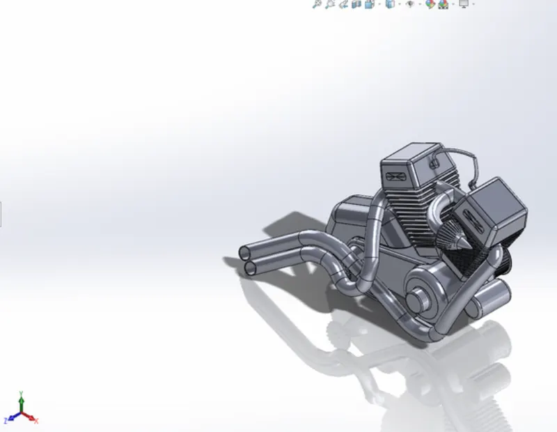
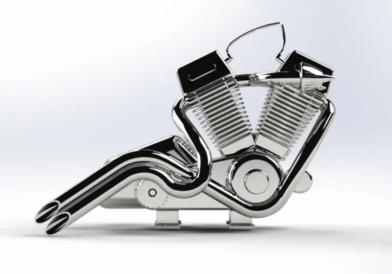
11. Engine:
- The engine, apparently known as the heart of a vehicle includes parts such as spark plug, inlet value, outlet value, cyclinder and motor. Motorcycle engines are typically two-stroke internal combution engines.
- Features such as boss extrude, cut extrude, revolve, sweep, projected curves, composite curves, fillet, chamfer, mirror, linear pattern and circular pattern were used to model the engine.
Model image
Rendered image
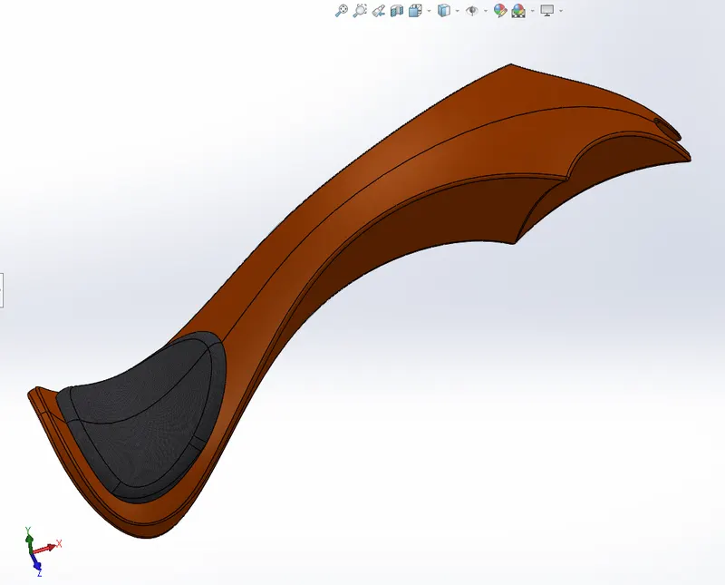
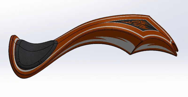
12. Gas tank:
- The gas tank stores the fuel required to run the engine.
- Unlike the other parts of the chopper, the gas tank was designed by using surface modelling using features like surface fill, boundary fill, surface sweep, extrude surface and projected curves.
Model image
Rendered image
Features used:
Boss extrude: This feature is used to expand the object in 3D according to sketch plane.
Extrude cut: Extrude cut feature used to cut/remove the 3D object in linear path according to sketch.
Fillet: Fillet is a feature used for making round internal or external edges to avoid sharp edges and make it smooth.
Lofted boss/bass: Lofted boss is a feaure used to achieve complex shaped. It does this by interpolating surfaces between various cross-sections of a model. These cross-sections can be sketches, faces, or edges.
Split: Split tool is used to split single solid part into two solid parts. It is used to project an entity onto other surfaces or curved/planer faces.
Dome: Dome is a feature used to make dome shaped extrude including elliptical dome.
Shell: Shell feature is used to make to hollow space in solid part by selecting outer wall of the solid part and so removes the inner parts. It is also to reduce the specific thickness.
Combine: Combine tool is used to make intergration of two solid parts which intersect each other as same solid part.
Chamfer: Chamfer is used to make a sharp edge or corner slightly tapered rather than being a perfect square.
Linear pattern: The linear parent is used to create a different number of instances required to create the pattern linearly.
Circular pattern: Circular pattern is a feature used to make 3d feature into circular pattern according to number of insistences.
Revolve boss/base: Revolve feature is used to make cylinderical or circular 3d extrude along with a given reference axis as per drawn sketch.
Revolve cut: Revolve cut is used to cut or reduce the extrude of cylinderical round surface.
Move/Copy body: This feature is used to move/copy the 3d body to one place to another place.
Mirror: Mirror is used to mirror a feature or body by reference of the selected plane.
Sweep: This feature is used to sweep any kind of fully defined sketch along with the path.
Sweep cut: Sweep cut is same as sweep feature but its diorectly proportional to sweep which makes a cut along with the sweep path.
Boundary surface: Is used to make a surface in between two finished surfaces.
Knit surface: Loft surface is used to knit the two free edges or open edges of the surface together also it also it reduces the gap between the two edges of the surface.
Surface trim: Primarily used to cut away material from a surface, and provides two modes: Standard and mutual.
Projective curve: Projective curve is a 3d curve which is projected on the basis of the two different 2d curves intwo different planes.
RENDERING
Rendering or image synthesis is the automatic process of generating a photorealistic or non-photorealistic image from a 2d or 3d model using a computer program. The resulting image is refered to as the render.
Major categories of Rendering
-Real-time rendering
-Pre-rendering
Software used
- Photoview 360
- Solidworks visualize.
ASSEMBLY OF AMERICAN CHOPPER
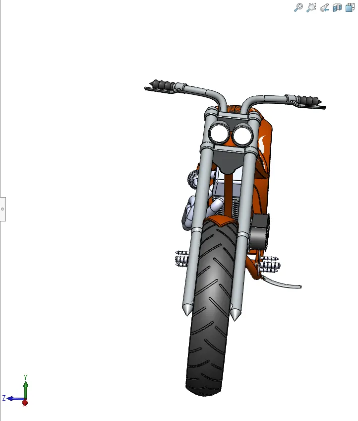
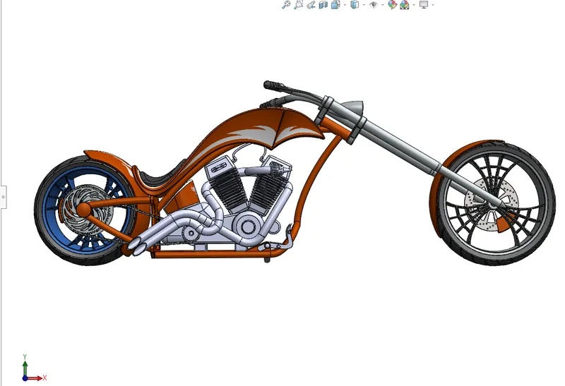
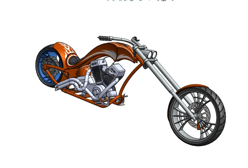
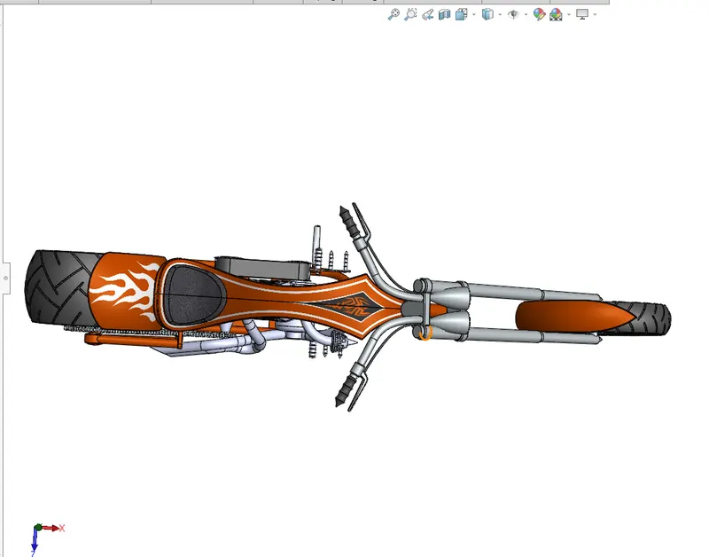
- All the parts were assembled in a solidworks assembly fill by inserting each part, one after the other using suitable mate relations.
1. Mates:
Mates create geometric relationships between assembly components. As you add mates, you define the allowable directions of linear or rotational motion of the components. You can move a component with in its degrees of freedom, visualizing the assembly behavior. some of the mates used during the assembly process are
- Anglemate
- Reference entity for angle mates
- Coincident mate
- Concentric mate
- Distance mate
- Lock mate
- Parallel and perpendicular mates
- Tangent mate
Front view of the assembled chopper
Side view
Isometric view
Top view
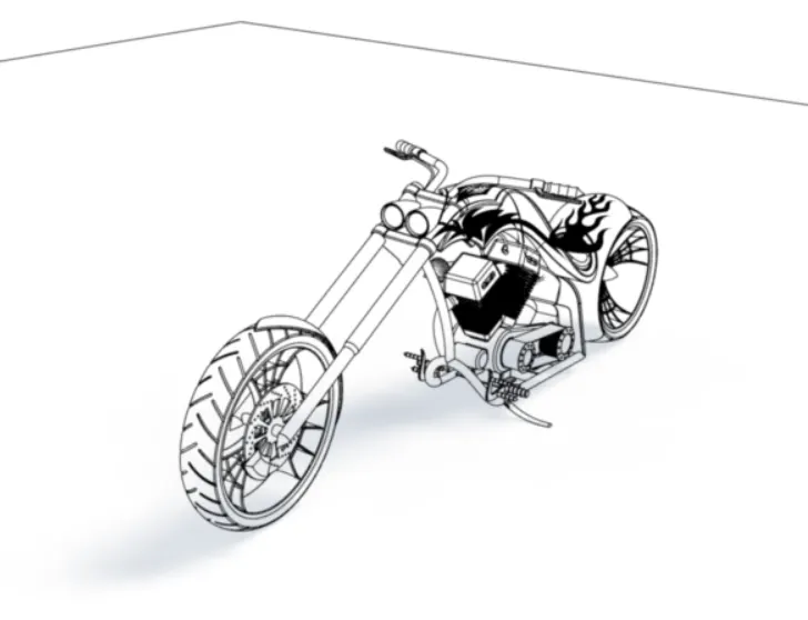
Camera view
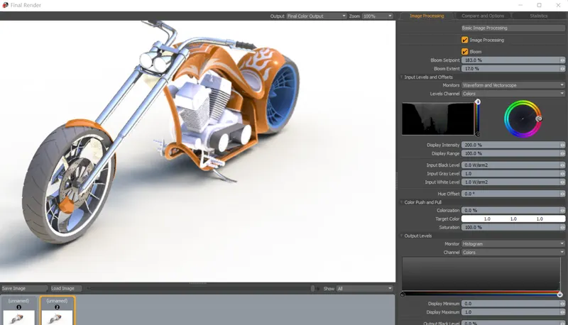
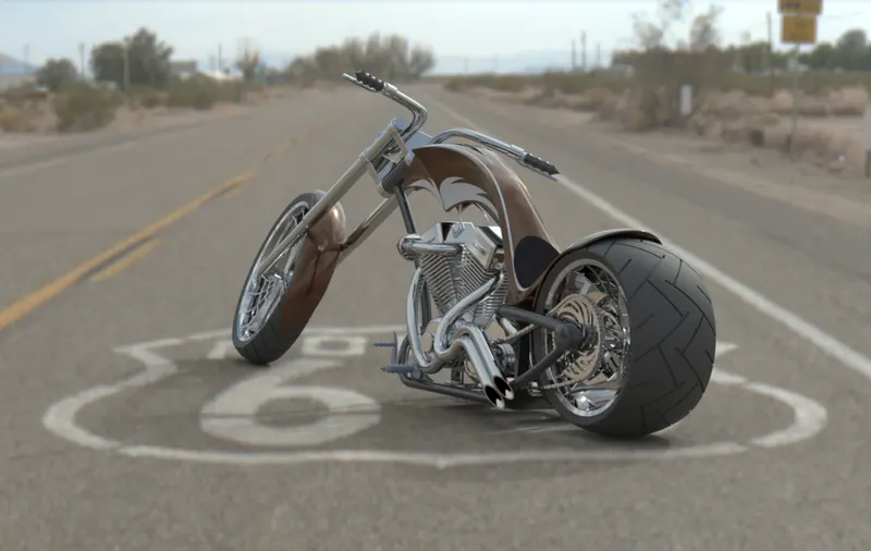
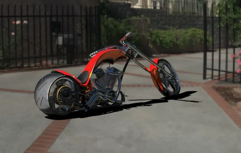
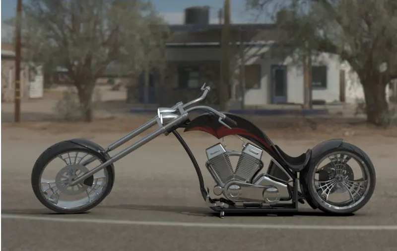
Rendering of American chopper
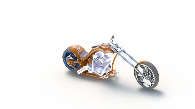
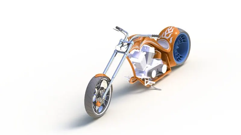
Solidworks visualize allows you to leverage your 3D CAD data to create photo-quality content in the fastest and easiest way you can from images to animations, interactive web contest, and immersive Virtual reality. Bring your products to life. Solidworks visualize is the camera for your CAD data
Some of the rendered images are shown
Conclusion
Thus, the parts of the AMERICAN CHOPPER are designed and assembled using SOLIDWORKS and are rendered to photorealistic images using Photoview 360 and Solidworks Visualize.
Assembly and parts link:https://drive.google.com/file/d/1RVhIG1aqHJszGlHeCQU5rqF11_JSSw4m/view?usp=sharing
Chopper Render link:https://drive.google.com/file/d/132-RKDjHyoVpG-UdE7VMY5iR49GsO7WS/view?usp=sharing