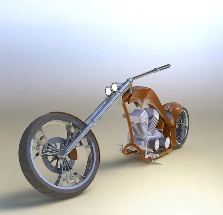
Photo Realistic Rendering
DESIGN AND ASSEMBLY OF AMERICAN CHOPPER BY USING SOLIDWORKS
OBJECTIVE
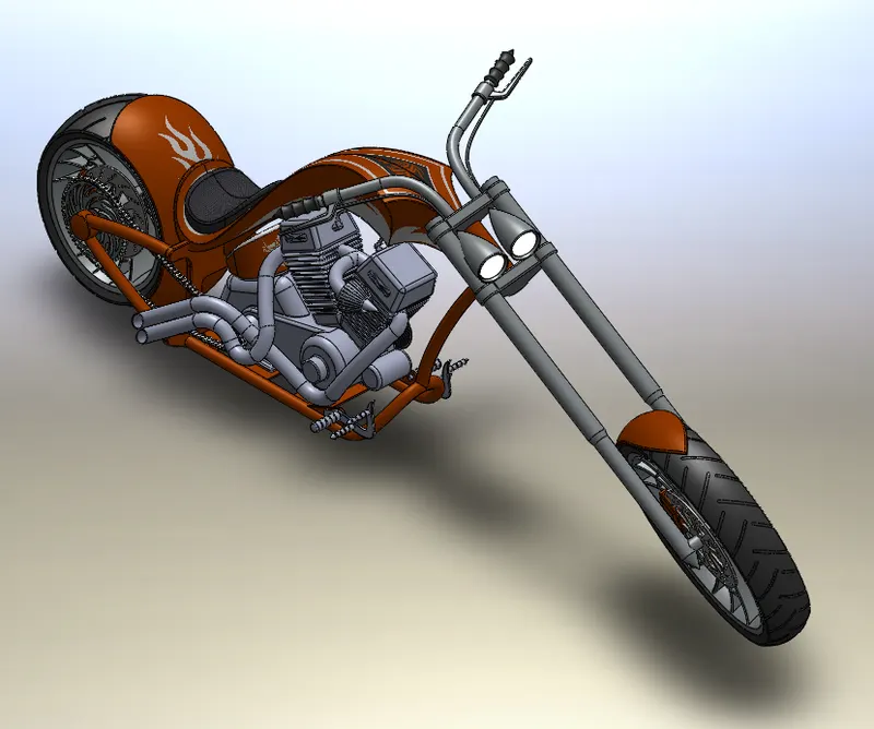
In this project, we will work in the SolidWorks environment, and here we will get a brief idea about the different options available in Solidworks and their uses under different conditions. Here we will work on a model i.e, an American chopper by using different tools and commands in SolidWorks, and also we can learn the procedure to design and assemble an American chopper by using Solidworks.
INTRODUCTION
A chopper is a type of custom motorcycle. That employs radically modified steering angles and lengthed forks for a stretched-out appearance. Some of the characteristics feature of choppers are long front ends with extended forks often coupled with an increased rake angle, hardtail frames(frames without rear suspension), short handlebars, lengthed or stretched frames larger than front wheels.
METHODOLOGY OR APPROACH
PART MODELLING
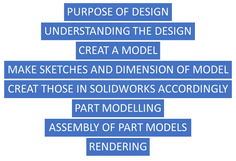
Here we can create a part according to our sketch which has been taken from research and analysis and also by conceptual sketching through solid feature modeling and the parts can modify as per the required design.
The main parts of the chopper are-
Here we required the following parts of the chopper for assembling in Solidworks
1. Transmission belt
2. kickstand
3. Front fender
4. Rear fender
5. Oil tank
6. Chain
7. Pedal
8. Front wheel
9. Rear wheel
10. Front fork
11. Chassis
12. Engine
13. Gas tank
1. TRANSMISSION BELT
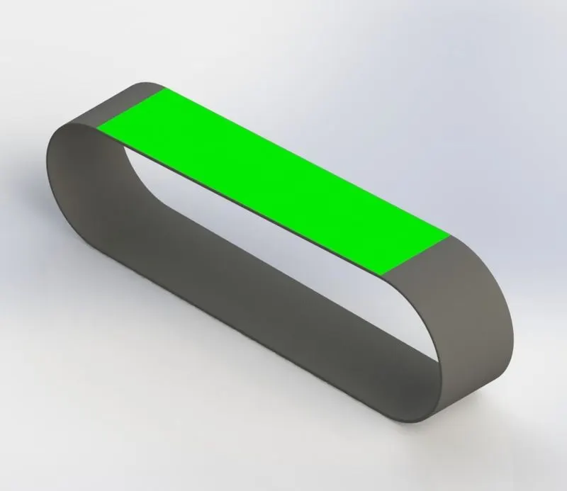
A transmission belt is used for the power transmission from the engine to the gearbox.
COMMANDS REQUIRED-
- Sketch
- Offset
- Extrude
- Fillet
- Appearance
The following procedure is used to create the transmission belt-
- Open Solidworks then select the "new part" to create a new part in Solidworks
- Rename the default planes as
Front plane-front plane lsw
Top plane-Top plane lsw
Right plane-Right plane lsw
- Then select the front plane to create a 2D sketch on it.
- By using offset create an offset entity of that sketch.
- Extrude it and make it a solid body by using the boss extrude command in the features tab.
- Give fillet as per required.
- Give the desired appearance to the transmission belt. Save the part.
2. KICKSTAND
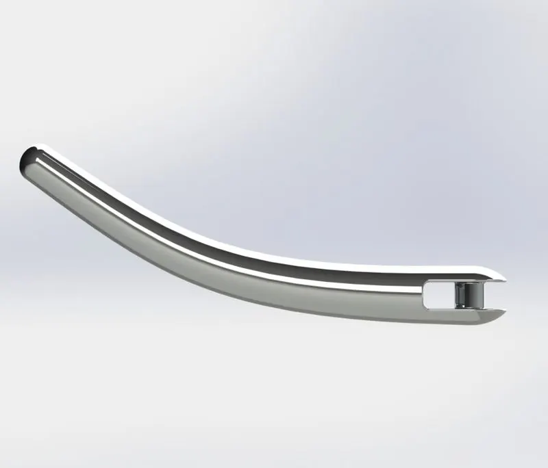
It is used to park the bike easily for a short period. It is more convenient for use in heavy vehicles.
COMMANDS REQUIRED-
- Sketch
- Loft
- Reference geometry
- Dome
- Extruded cut
- Fillet
- Split
- Appearance
The following procedures are used to create the kickstand-
- Open Solid works then select the new part to create a new part.
- Choose the front plane to create a sketch on it.
- Enter a new plane on that sketch by choosing a suitable reference.
- Create a 2D sketch on that plane and make the sketch fully defined.
- Then use the loft command to create a loft.
- Create a dome face on both ends of the kickstand with the help of the dome command.
- Use the split option to create a flat face at the last end side.
- By the use of extruded cut command remove unwanted things.
- After the application of appearance save the part file.
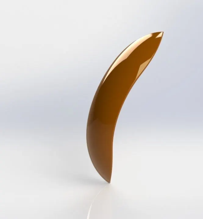
3. FRONT FENDER-
The front fender is mounted above the front wheel, which is used to protect the rider and chopper parts from dust, mud, and other particles.
COMMAND NEEDED-
- Sketch
- Offset entities
- Extend entities
- Trim entities
- Dynamic mirror
- Spline
- Split
- Fillet
- Appearance
Following procedures are used to create the front fender-
- Open Solidworks then click the new part to create a new model.
- Rename the default planes as
- Front plane- vertical plane
- Top plane-central plane
- Right plane-mid plane
- Choose the front plane to create a sketch on it.
- By using offset entities, extend entities, trim entities, and apply dimensions to make fully defined.
- Select the dynamic mirror command for the drawn sketch.
- Use the split command to cut the extra things.
- Give fillet then apply appearance.
- At last, save the part file.
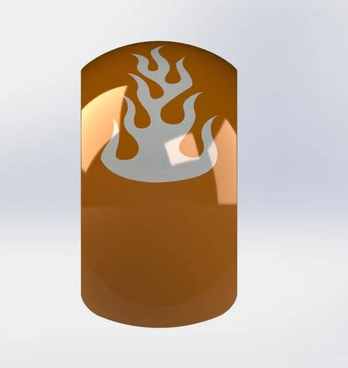
4. REAR FENDER-
Typically it is used for protection from the dust, mud, rocks, and liquids being thrown by the tire. It also covers all the rear wheel arrangements and provides rigidness.
COMMANDS NEEDED-
- Sketch
- Offset entities
- Trim entities
- Revolve
- Appearance
The following procedure is used to create a rear fender-
- Open solid works then select the new part to create a new part.
- Then change the names of the default planes as
- Front plane- vertical plane rear fender
- Top plane- central plane rear fender
- Right plane- midplane rear fender
- Then select the center plane for sketching.
- Then draw a 2D sketch by using sketch commands, splines, trim tool, extend entities command, and apply relation or dimension for the fully defined sketch.
- Sketch the solid body by using revolve boss command.
- Then create the desired shape with the help of a dynamic mirror and split command.
- Then change the appearance of the rear fender and save the model.
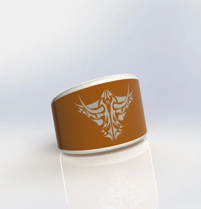
5. OIL TANK-
Its main purpose is to store oil and supply it to the engine when the engine is running so the oil tank should be hollow from the inner side.
COMMANDS NEEDED-
- Sketch
- Dynamic mirror
- Boss extrude
- Combine
- filate
- shell
- appearance
The following procedure is used t create the oil tank-
- open solid works then select the new part to create a new model.
- Rename the default planes as
- Front plane – mid planes
- Select the top plane for sketching and make a 2D sketch on it and apply dimension and relation to make it fully defined.
- By using the dynamic mirror and boss extrude make It a solid body.
- Then select midplane, sketch 2D drawings, then extruded it by boss extruded command.
- By using the combine command in the features tab combines the two extruded bodies, here select the common body option to get the desired shape.
- Apply appearance and save the part files.
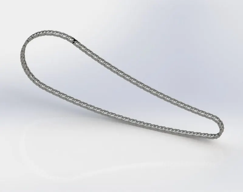
6. CHAIN-
It is an easy and effective way of transmitting power from the engine to the rear wheel by using the chain. It requires less maintenance. it is often conveyed by a roller, passing over a sprocket gear, with each of the gears meshing with the holes in the links of the chain.
COMMANDS NEEDED-
- Sketch
- Boss extrude
- Fillet
- Curve-driven pattern
- Mirror
- Appearance
The following procedure is used to create the chain-
- Open the Solidworks, then select the new part to create a new model.
- Rename the default planes as
- Front plane- midplane
Top plane- center plane
Right plane- front plane
- Select the midplane to make a 2D sketch on that plane.
- Create a path that guides the chain links.
- Create links by using the 2D sketch and give dimensions and apply relations.
- Then use a curve-driven pattern and fillet on it.
- At last, change the appearance and save it.
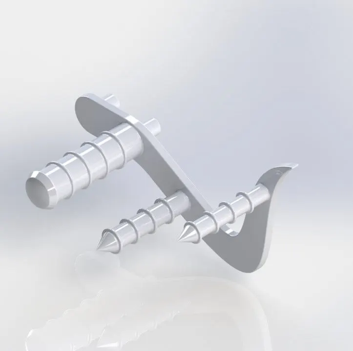
7. PEDAL-
It provides rigid support to the leg for resting and also it is used for breaking and shifting gears.
Commands needed-
- Sketch
- Boss extrude
- Revolved boss
- Dome
- Fillet
- Chamfer
- Linear pattern
- Appearance
The following procedure is used to create this part-
- Open solid works then select a new part.
- The select front plane for sketching then draws all the 2D sketches by using the sketch command and gives dimension to them.
- Make it solid bodies by using extruded boss command and give fillet to it.
- Apply linear pattern curve for the sketch.
- Change the appearance and save the part file.
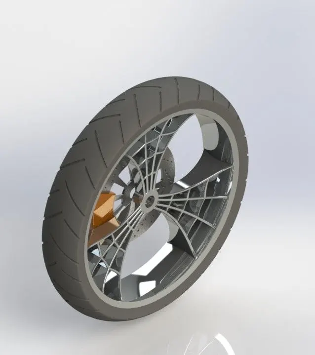
8. FRONT-WHEEL-
It is designed to absorb both the axial and radial forces, also gives the support for mounting different components such as brake and suspension.
COMMANDS NEEDED-
- Sketch
- Revolve
- Bos extruded
- Cut extrude
- Circular pattern
- Linear pattern
- Combine
- Revolve cut
- Extruded cut
- Circular pattern
- Fillets chamfer
- Appearance
The following procedure is used to create the front wheel-
- Open solid work then select the new part to create a new model.
- Select the front plane create a sketch on it then make it revolved boss by using revolve boss command.
- Then select the right plane and make a 2D sketch on it, apply relation, and give dimension to make it fully defined.
- Make it a solid body by using boss extrude and revolve boss then apply the circular pattern on it.
- Then combine these bodies.
- After that create the caliper, disc plate, and tire along with the wheel.
- Then apply appearance to all the parts as required and save the part file.
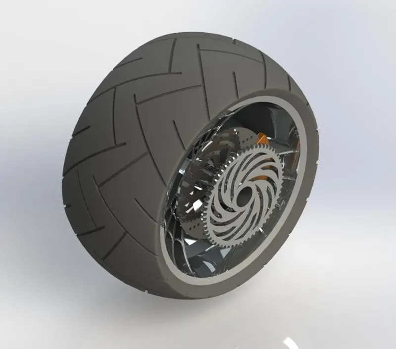
9. REAR-WHEEL-
The rear wheel supports the maximum weight of the chopper along with the weight of the driver. In the vehicle, the power is transmitted to the rear wheel from the engine. It gives the mounting place for the brake and rear sprocket.
COMMANDS NEEDED-
- Sketch
- Revolve boss
- Cut extrude
- Boss extrude
- Circular pattern
- Combine
- Revolve cut
- Fillet
- Chamfer
- Appearance
The following procedure is used to create rear wheel-
- First, open solid work then select the new part to create a new model.
- Select the front plane create a 2D sketch on it by sketch command and make it revolve.
- Then select the right plane, create a sketch on it as per required then extruded it by extruded boss command, create a circular pattern and revolve cut it.
- Combine the bodies by combine command.
- Then change the appearance and save the part.
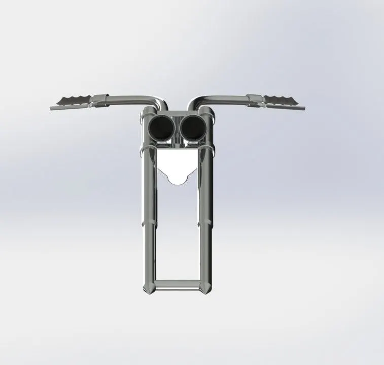
10. FRONT FORK-
The front fork connects a motor cycle’s front wheel and axle to its frame, typically via a yoke also known as a triple clamp, which consists of a yoke joined to a lower yoke steering. it gives the way to mount the suspension and brakes.
COMMANDS NEEDED-
- Sketch
- Revolve
- Boss extrude
- Fillet
- Linear pattern
- Cut extrude
- Dome
- Revolve cut
- Project curve
- Mirror
- Sweep
- Combine
- Appearance
The following procedure is used to create the front fork-
- First, open Solid works then select the new part to create a new model.
- Start sketch by using the sketch command on the front plate.
- Create solid bodies using those sketches with the help of revolving boss, boss extrude, and fillet.
- Then create handlebars with the help of 2D sketches, project curve, and sept boss.
- By using the project curve we can create a 3D curve using multiple curves.
- Mirror those bodies then combine them properly.
- Then change their appearance and save the part file.
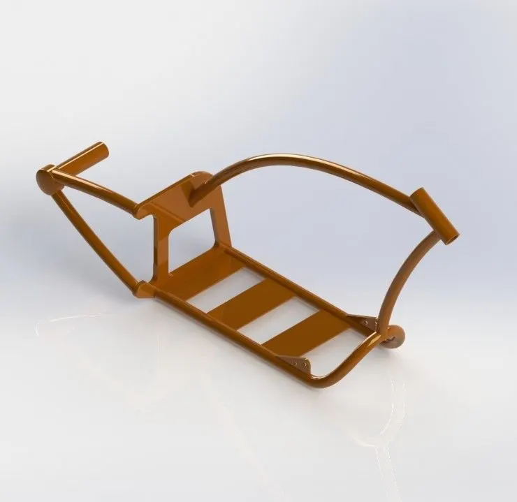
11. CHASSIS-
It is also known as the frame is the foundation structure of any bike that supports all the components. The main purpose of the chassis is to bear the weight of the bike.
COMMANDS NEEDED-
- Sketch
- Convert entities
- Project curve
- Swept
- Mirro
- Chamfer
- Dome
- Split
- Trim
- Combine
- Appearance
The following procedure is used to create the chassis-
- Open Solidworks then select create a new part to create a new model.
- Rename the default plane as
Front plane- midplane chassis
Bottom plane- top plane
Right plane- right plane
- Select the midplane then enter the sketch plane on it and create solid bodies and mirror them along the midplane.
- Using, the split tool cut the extra things that don’t need.
- Combine the bodies to make a single body and apply appearance.
- At last, save this part file.
12. ENGINE-
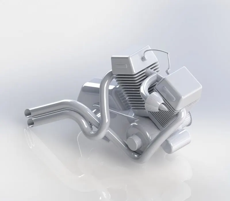
It is the main part of any vehicle.
It converts the chemical energy to heat energy by running the air-fuel mixture inside the running engine cylinder.
COMMANDS NEEDED-
- Sketch
- Boss extrude
- Revolve
- Fillet
- chamfer
- Dome
- Extruded cut
- Chamfer
- Linear pattern
- Mirror
- Project curve
- Appearance
The following procedure is used to create the engine
- First, open solid work then select the “create a new part” to create a new model.
- Then select the front plane for sketch and then bring the sketch picture on the midplane of the engine and then change the x and y direction position and transparency as per required.
- Rename that sketch picture to a blueprint sketch picture.
- Then draw 2D sketch b using planes, sketch commands and give dimensions and relations as required to fully define that sketch.
- Then change the appearance of the engine and save the part file.
13. GAS TANK-
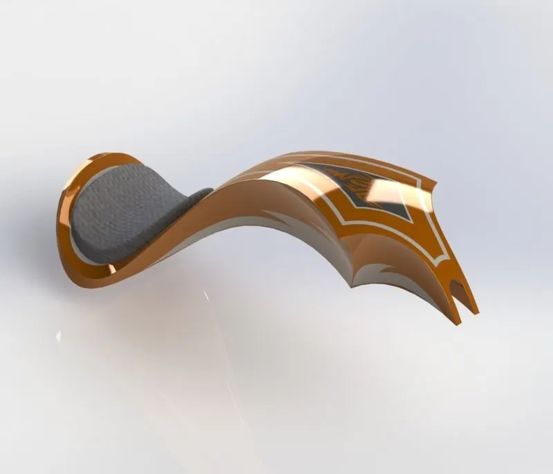
The main purpose of the gas tank is used to store the gas and supply the gas when the engine is required.
COMMANDS NEEDED-
- Sketch
- Swept surface
- Trim surface
- Project curve
- Surface loft
- Surface boundary
- Surface knit
- Split line
- Mirror
- Surface extrude
- Fillet
- Cut
- Sweep
- Shell
- Appearance
The following procedure is used to create a gas tank-
- First, open Solidworks then select “create new part” to create a new model.
- Then change the default plane names as
Midplane- midplane gas tank
Top plane- bottom plane gas tank
Right plane- front plane
- Select the midplane for sketch and brings the sketch picture in the midplane gas tank and then change the x and y position.
- Then draw the 2D sketches give dimensions and use project curve, lofted surface, and boundary surface commands to make the surface body.
- Then make a solid body and apply the shell feature on it to create space from the inner side.
- Change the appearance and save that file.
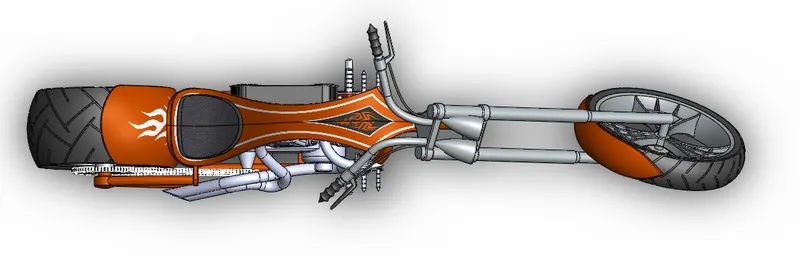
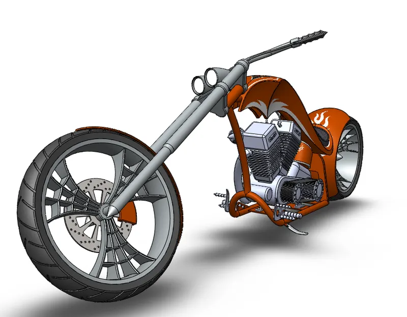
ASSEMBLY OF CHOPPER-
FRONT VIEW
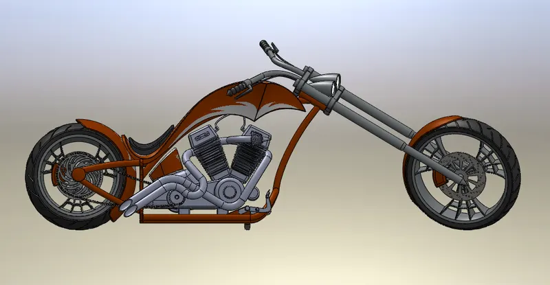
RIGHT VIEW
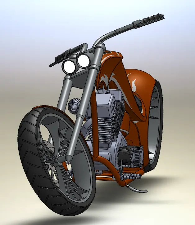
ISOMETRIC VIEW
TOP VIEW
CAMERA SETUP VIEW
RENDERING IMAGE OF CHOPPER
CONCLUSION
Here we learned how to create, design, assemble and render a model in Solidworks by using options and commands available in solid work. In this project, we learned about the scene setup, scene composition and also get exposure to photo view 360 options for a detailed rendering.