Photo Realistic Rendering
AMERICAN CHOPPER
- Objective:
The objective is to give a brief description about the design and the designing methodology used to build an American Chopper. This also includes the assembly of the American Chopper. And the rendering of the parts and the final rendering of the model of American Chopper.
- Introduction:
A chopper is a type of custom motorcycle which emerged in California in the late 1950s.A chopper employs radically modified steering angles and lengthened forks for a stretched-out appearance. Some of the characteristic features of choppers are long front ends with extended forks often coupled with an increased rake angle, hardtail frames (frames without rear suspension), very tall "ape hanger" or very short "drag" handlebars, lengthened, or stretched frames, and larger than stock front wheels. The "sissy bar", a set of tubes that connect the rear fender with the frame, and which are often extended several feet high, is a signature feature on many choppers.
- Designing Methodology/Approaches:
The designing methodology used to build the American Chopper is very simple and. It uses basic tools and some features to design and assemble the parts of chopper. The basic tools used to design chopper are sketch tools (line, circle, ellipse, spline, and many more which we will discuss later), extrude surface, sweep boss, projected curve and many more features to go.
The main designing methodology or approach is assuming a rough sketch of our part in the mind and then making a layout of it and then after getting near to the assumed design give values and dimensions to the part.
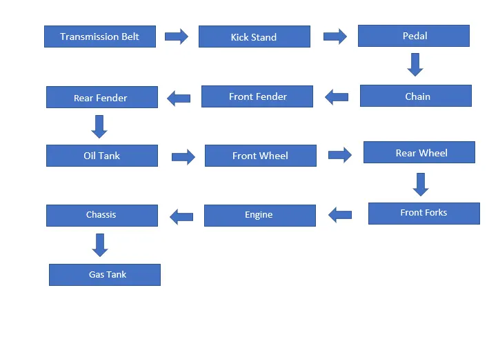
Now we will discuss the designing of chopper in detail with the help of the flow chart we will complete each part and the designing approaches or methodology used to build those parts.
- Tools and Features
Now we will discuss about the tools and the features we used in the solid works to create our American Chopper.
- Line Tool: This tool is used to draw lines. These lines can be centre line, construction line, solid line and these lines can be horizontal, vertical, or at any angle.
- Smart Dimension: It is used to give a dimension to our sketch so that it is fully defined.
- Offset Tool: This tool allows us to offset any line or shape quickly and easily.
- Extrude Boss Base: This tool helps us to make our sketch a solid body. It converts our sketch from 2D to 3D by adding one more dimension to it. Extrude boss can be done in one or two directions.
- Appearance: This feature allows us to add a realistic appearance to our sketch depending on our requirement we can add metal, paint, light, cloth, rubber, or any material which we want to add on our part.
- Spline Tool: This tool helps us in sketching curves which are difficult to draw with the help of other arcs or to give accurate curves according to our need. The splines also need to be activated by giving them dimension, direction, and weight.
- Circle: This tool is used to draw circles.
- Loft Surface: Loft surface tool is used to generate surfaces by multiple 3D curves or existing edges creating a smooth tangency between the selected curves. Match points are created between each selection denoting the and the path of the loft surface.
- Extrude Cut: This tool is used to cut material from the existing solid body.
- Split Line Tool: This tool trim or cut the material from the solid, surface, curve, plane, or surface spline.
- Fillet Tool: This tool is used to round the corner or smooth the sharp edges of the parts.
- Arc Tool: This tool is used to draw arc. Arc can be drawn with help of points and the edges of other shapes.
- Linear Sketch Pattern: This feature helps us to create number of patterns from a sketch entity in a linear manner and we can offset distance between them.
- Trim Tool: This tool is used to trim the excess lines and curves from the sketch.
- Straight Slot: This tool is very helpful in creating closed shape with arcs and lines tangent to it. This tool is like rectangle or circle tool.
- Circular Pattern: This tool helps us to create feature, body, or face in circular manner. This tool duplicates our feature and arrange them in circular direction.
- Revolve Boss Base: This feature is used to create a 3D solid model around an axis. The sketch can be revolved around an axis to add material to it.
- Mirror Entity: This tool is used to mirror the sketch horizontally or vertically about an axis.
- Combine: This feature is used to combine to solid bodies or 3D models to create a new model or bodies. It is most often used in surface modelling as it allows us to take moulds of created parts for moulds operation.
- Shell: This tool hollows out a part, leaves the selected faces and creates a thin-walled features on the remaining faces.
- Flow chart of parts of American Chopper:
- Description of Parts:
- Transmission Belt
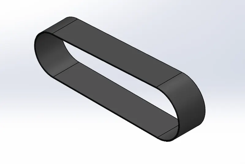
- The designing method of transmission belt start with the line and some curves.
- Then the sketch is given an offset value to get the thickness of the belt and then we do a extrude boss base and apply an appearance of rubber this completes our Transmission Belt.
- Kick Stand
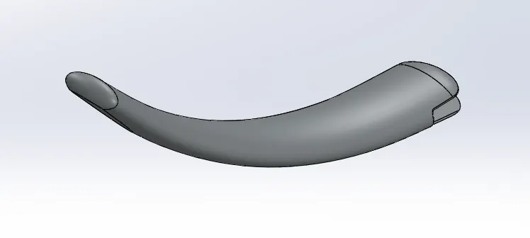
- The kick stand designing start with the help of circles and splines.
- First the circle is drawn and then a spline from the centre of circle is drawn, and then again a circle is drawn at the other end of the circle.
- Now we will do a surface loft and it will follow the path of the spline and both the circles.
- Next thing is to do a extrude cut to make space for pins to attach it to the chassis.
- Now we will add some fillet at the sharp edges. And we will apply an ellipse dome at the end parts of the kick stand.
- We will also a make a split cut at the end where it touches the ground. And the part will be completed after applying an appearance to it.
3.Pedal
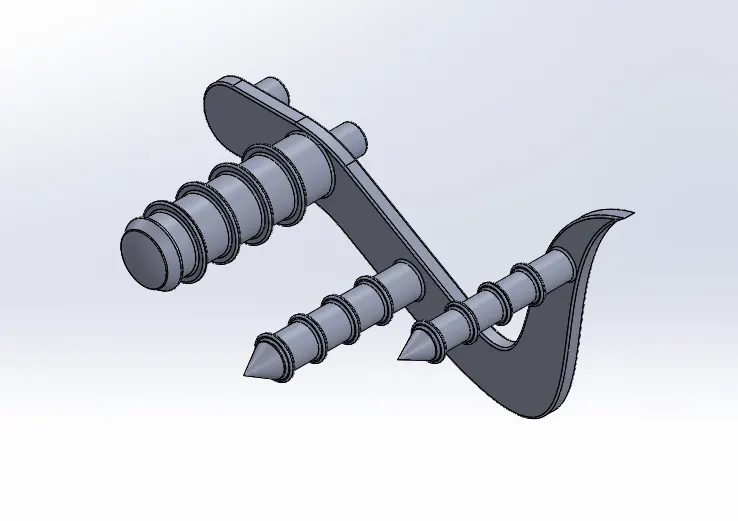
- We will start by making some lines and arc and some splines to give it the exact shape.
- Then after this we will draw some circle and make them extrude these are for to place the foot.
- Then we will add some grip to these by adding small circular plates with the help of linear sketch pattern feature.
- Then on the other side of the plate we will draw pins so that we can mount it to the chassis. Now we will add some fillets to it. And finally, after applying the appearance our part is ready.
- Chain
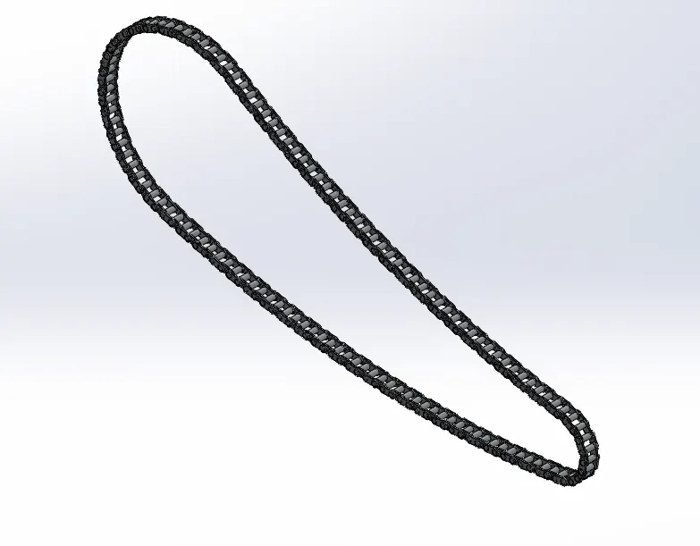
- To design a chain, a path is to be created and then links and pins are to be added to the path to complete the chain.
- The path can be sketch with the help of circles and the arcs.
- Now inner and outer links to be created with the help of circles, arcs, and straight slot.
- Now start putting the links one by one on the path one inner link then outer and so on.
- With, the help of extrude boss base we will create the pins and the link plates.
- Now we will do a circular pattern and apply it to the sketch in four different parts according to our curves so that it gives us a real look.
- Front Fender
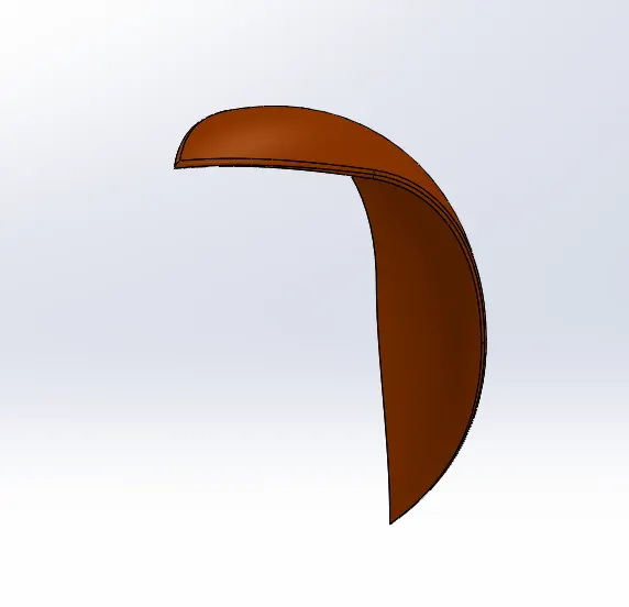
- To start design of front fender, we need to start with, drawing some lines and arcs.
- After this we will do revolve boss base in both the direction, from the origin at certain degrees.
- Now we will draw a spline at one end of the fender and after getting the proper curve and the shape for our fender we will mirror it and make a split cut.
- We will do this process with the other end also. We will add some fillets to and will also add appearance to it.
- Rear Fender
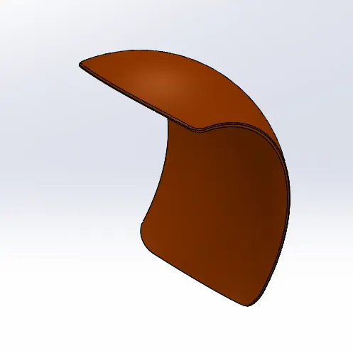
- The designing method of rear fender is same as that of the front fender the difference is in between the dimensions and the design.
- We will start with sketching some lines and arcs.
- After this we will do revolve boss base in both the direction, from the origin at certain degrees.
- Now we will draw a spline at one end of the fender and after getting the proper curve and the shape for our fender we will mirror it and make a split cut. We will do this process with the other end also.
- We will add some fillets to and will also add appearance to it.
- Oil Tank
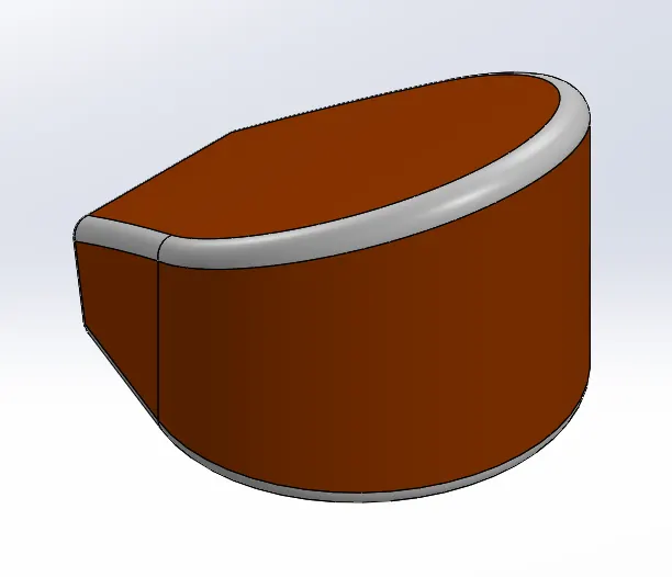
- To design oil tank some lines and arcs are to be drawn.
- Then we will do the extrude boss base.
- Now again we will draw a different shape on the newly created surface. Then again, we will do a boss extrude.
- Now we will use the combine feature to combine both the extruded surfaces and we will get our required shape of the oil tank.
- We will use the shell tool to make it a hollow part.
- Front Wheel
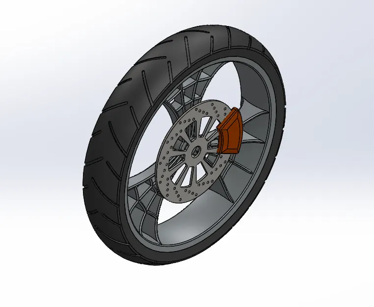
- First, we start by drawing some lines and arcs for the rim and the tyre.
- Then we will do revolve boss base.
- Next step is drawing some splines for the spider web design of rim.
- Then we will draw our rotor plate with the help of circles and linear and circular patterns to remove material and to add design to it.
- Next thing is to make calliper with the help of lines and arcs.
- Rear Wheel
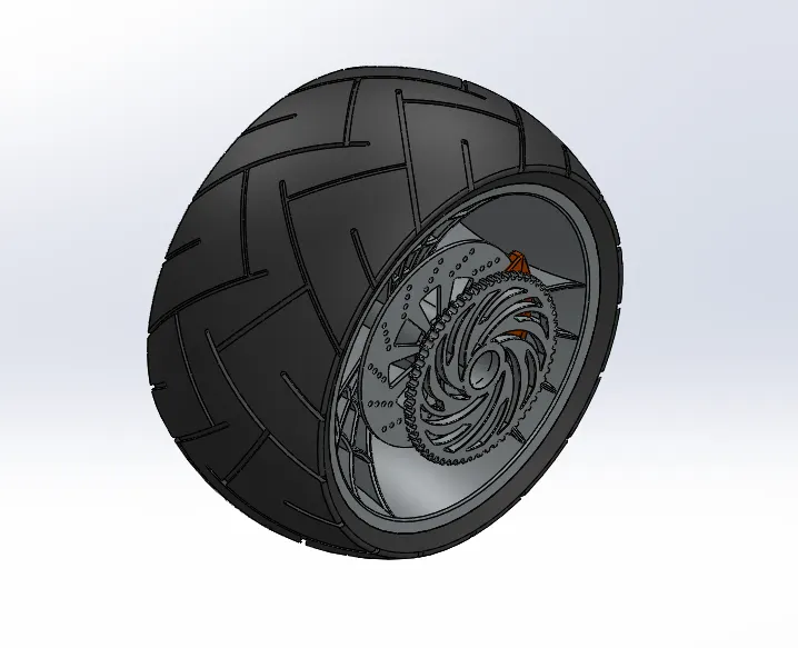
- The designing of rear wheel is same as that of the front wheel the only difference is of the sprocket.
- Sprocket is designed with the help of lines, arcs, and circle. Then we will make a extrude boss.
- Now we will do a curve pattern to the circle to make teeth at the plate.
- Next is to remove material from the sprocket.
- Front Forks
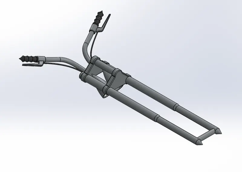
- The designing starts with the triple clamps.
- Designing of triple clamp starts will be in two parts. Some lines and circles are to be drawn to form a layout.
- Then we will do a boss extrude.
- Next step is to add fork with the help of lines and revolve feature.
- Next thing is to add handlebar with the help of spline, we will make a projected curve from these splines.
- Then add livers and grips and cables to the handlebar.
- Then after completing the one side of the triple clamp, we will mirror it and make it a single solid body.
- Now we will add headlights to it. We will draw some lines and to the revolve feature.
- Engine
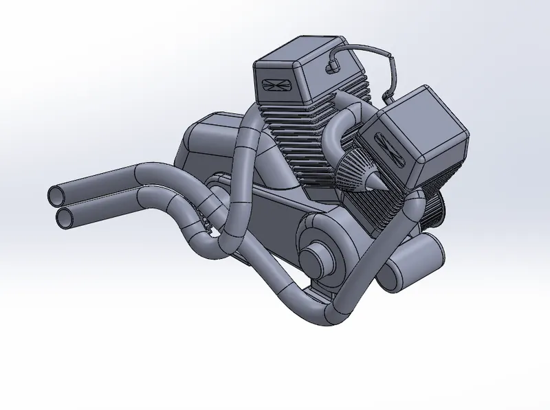
- Design of engine starts with drawing of body of the engine with the help of lines and arcs.
- Next step is to extrude the surface to make a solid body.
- Now we will draw the starter motor with help of circles and extrude it.
- Now we will draw the cylinder and add the fins to the cylinder body and do a extrude cut to make the fins.
- Next, thing is to draw the air intake to the cylinder. With the help of spline and sweep boss.
- Next, we will sketch some splines to make the exhaust from the cylinder. By doing sweep to the curve our exhaust pipes will be created.
- Now sparks plugs, and cables are to be design at the cylinder head.
- Chassis
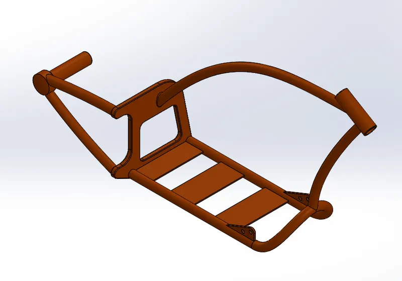
- The first step is to draw the back plate of the chassis with the help of lines and arcs.
- Now we will do a extrude boss base.
- Now we will draw some splines so that we can create structure to mount the rear tyre.
- Then we will draw some more splines to complete the chassis structure.
- Now we will do sweep boss.
- Now we will add some plates at the front of the pipes so that we can mount the pedal and kick stand.
- Now we will draw some plates with the line tool and extrude them so that we can place the engine on this plate.
- In the front we will make a hollow pipe so that our front fork can be mounted here.
- Gas Tank
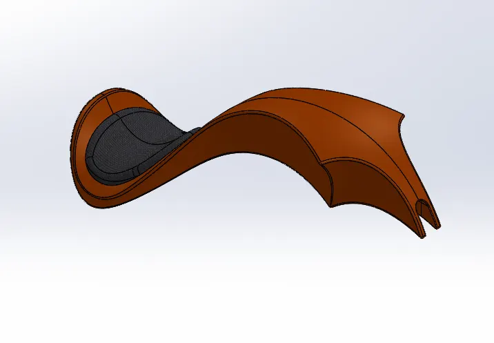
- To design the gas tank, we need to start from the front by drawing some splines and then doing a surface sweep of the part.
- Now again we will draw some more spline to draw the complete gas tank.
- Now we will add some lines in this curve so that we can do a Boundary surface.
- Next thing is to mirror the part and we will do a surface knit to it.
- Now we will sketch our seat at the back side of the gas tank by doing the surface extrude feature.
- Now again we will do the boundary surface to pack our gas tank from the bottom.
- Next thing is to cut the material from the bottom of the tank so that in can be mounted easily on the chassis.
- Assembly of American Chopper:
- The first part to assemble in the assembly of the chopper is the chassis.
- Next is the engine. We will make a coincident relation between the bottom of the engine and plates at the chassis. Will use some more relation so that it is fixed to the chassis.
- Now we will assemble the oil tank on the engine, and we will do some midplane relations with the chassis.
- Now we will mount the pedal and the kick stand at there respective positions by giving them some coincident relations.
- Next thing is the transmission belt on the engine.
- Then we will add the rear wheel and make it concentric with the hub at the chassis and make a midplane relation also.
- Now we will add fender by doing some plane relations with chassis.
- Next assemble part is the chain by giving it some concentric relation with the circular edges.
- Then the gas tank will be mounted on the chassis by giving some plane relations with the chassis.
- Then we will assemble the front fork to the chassis.
- And then finally, the front wheel and front fender is assembled to the front fork with the help of concentric relations and some plane relations.
And this completes our assembly of the American Chopper. All the parts are assembled and given relation to the chassis so that they don’t float and always get fixed to the chassis.
We also need to make some changes while doing the assembly in the original sketch of the parts so that the assembly looks good, and no parts get merge with each other.
- Camera Setup View
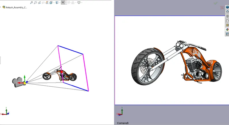
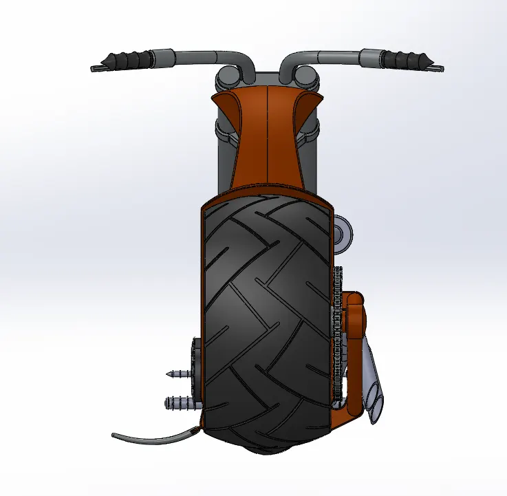
- Front View
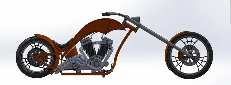
- Isometric View
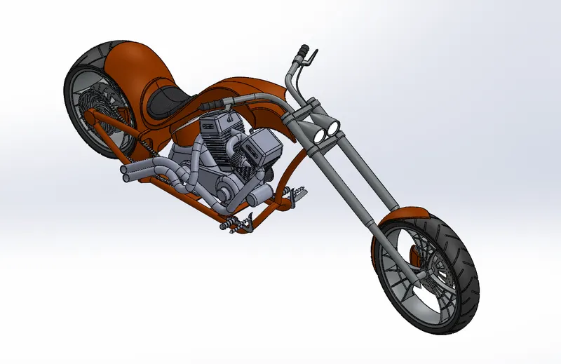
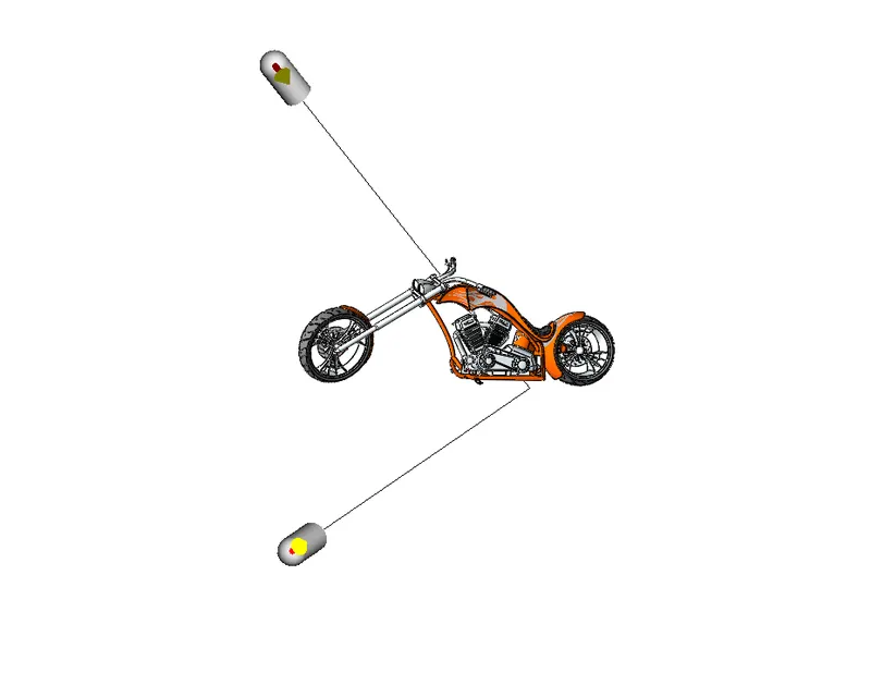
- Light Setup View
- Side View
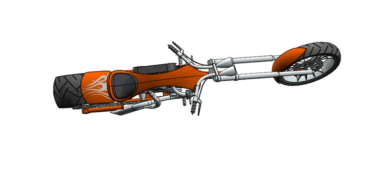
- Top View
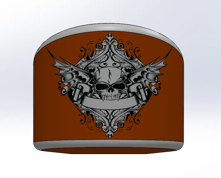
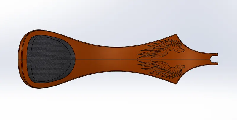
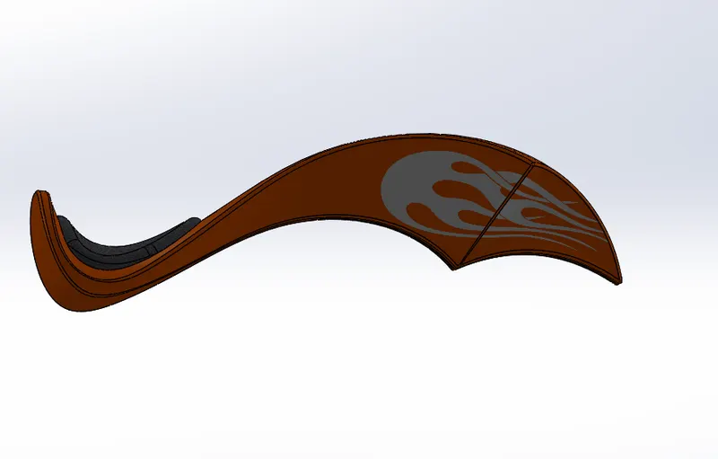
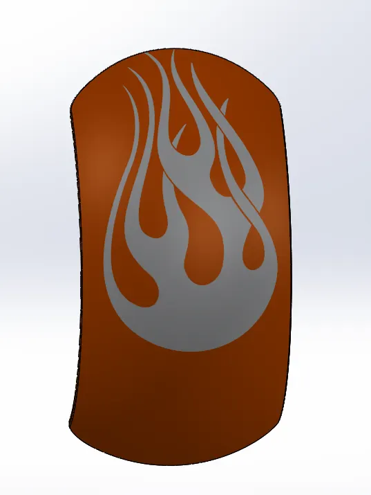
- Rendering Images of American Chopper:
- Conclusion:
Now we have completed the designing, assembly, and the rendering of the complete American Chopper. And we concluded that with the help of some tools and features can create and add design to our chopper and can build a complete chopper with those features and tools.