Photo Realistic Rendering
American chopper
Objective
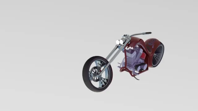
In this project i have designed , assembled and rendered the american chopper bike which is a customized one with the spider web rim and chrome plated. I have done my desinging by solid works 2016 and renderd only by photo 360.
Introduction
In this project i have designed american chopper by using solidwork 2016 software and i splited the parts to make easy and i design using refferd dimension finnaly i renderd it using solid works photo 360. i have listed the parts below .
Design methodology
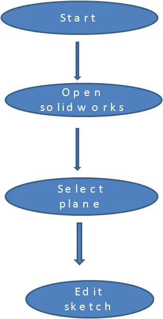
Description
chopper is built through solid featuring, surface modelling there are various component.
- transmission belt
- kickstand
- front fender
- rear fender
- oil tank
- chain
- pedel
- front wheel
- rear wheel
- front fork
- chassis
- engine
- gas tank
transmission belt
Transmission belt is used to transmit power from engine to gear box following feature is done
- sketch
- offset
- extrude
- fillet
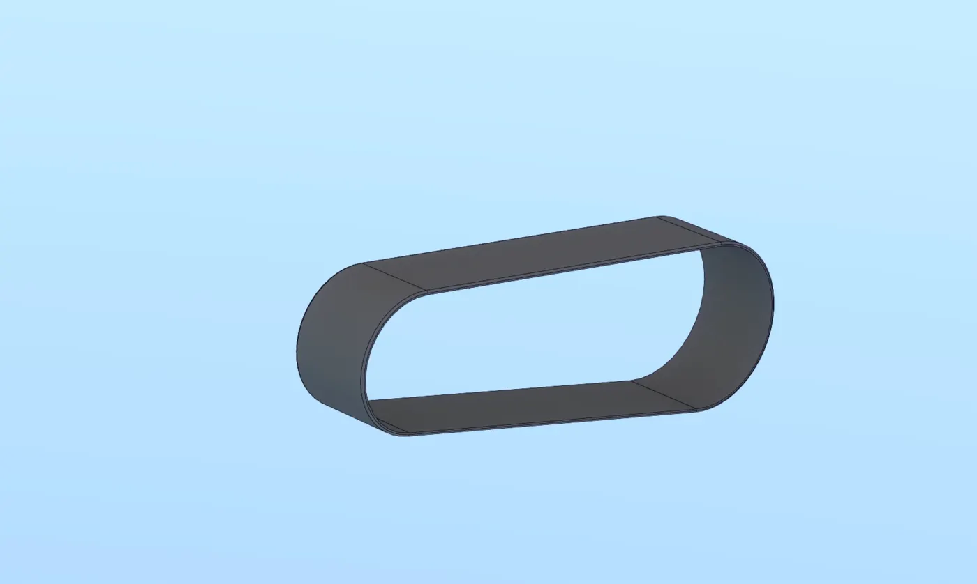
Description: In this part initially the sktech is extruded and then fillet is made.
Kick stand
it is used to support the chopper
- Loft
- dome
- extrude boss
- extrude cut
- split
- fillet
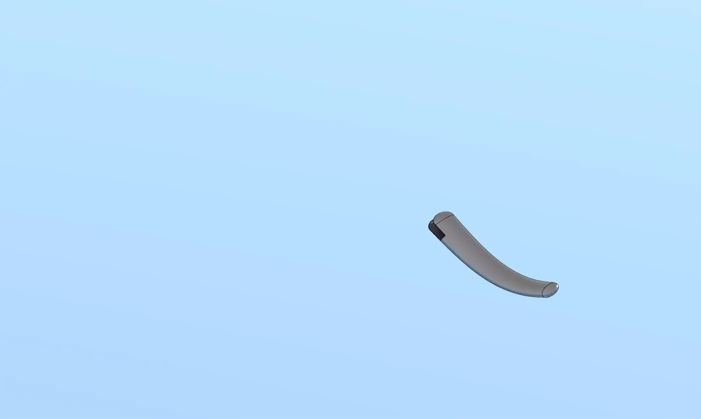
Description: In this part initially the sktech is extruded and then fillet is made in addition loft and dome is created and also extrude cut is done.
Front fender
It is used to protect wheels from dust, and also for good view
- sketch
- offset entities
- split
- trim entites
- revolve
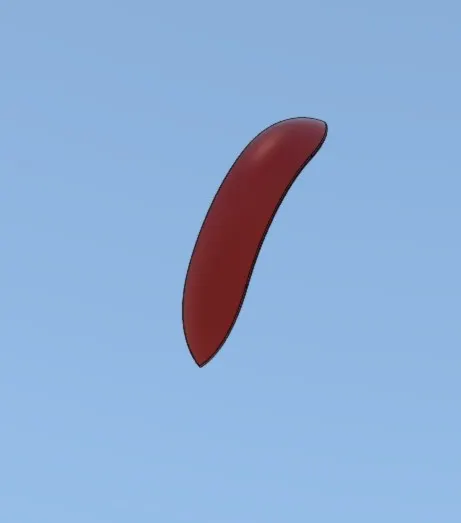
Description: intially the sketch is offseted and split lines are made and then finally revove is done.
rear fender
rear fender also do the same job of front fender but make may looks broad.
- sketch
- offset entities
- split
- trim entites
- revolve
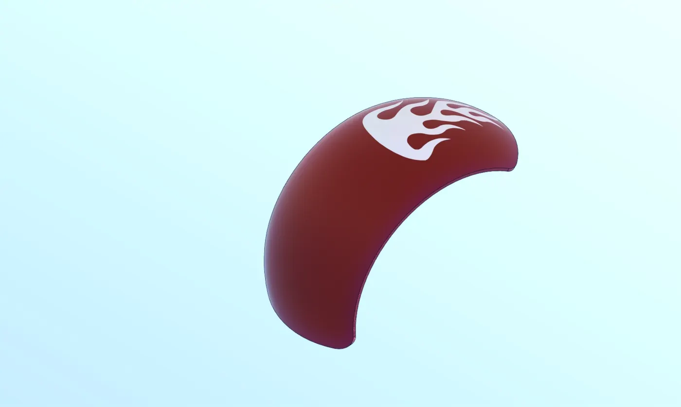
Description: intially the sketch is offseted and split lines are made and then finally revove is done.
Oil tank
oil tank is hollow solid body to store oil.
- Boss extrude
- combine
- fillet
- shell
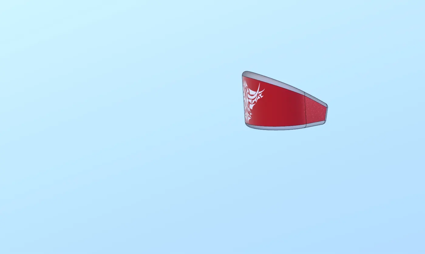
Description: initially the sketch is extruded and then fillet is made then the solid body is made shell.
Chain
it is created by sketch blocks ,linear pattern and mirror.
- sketch
- extrude
- curve driven pattern
- mirror
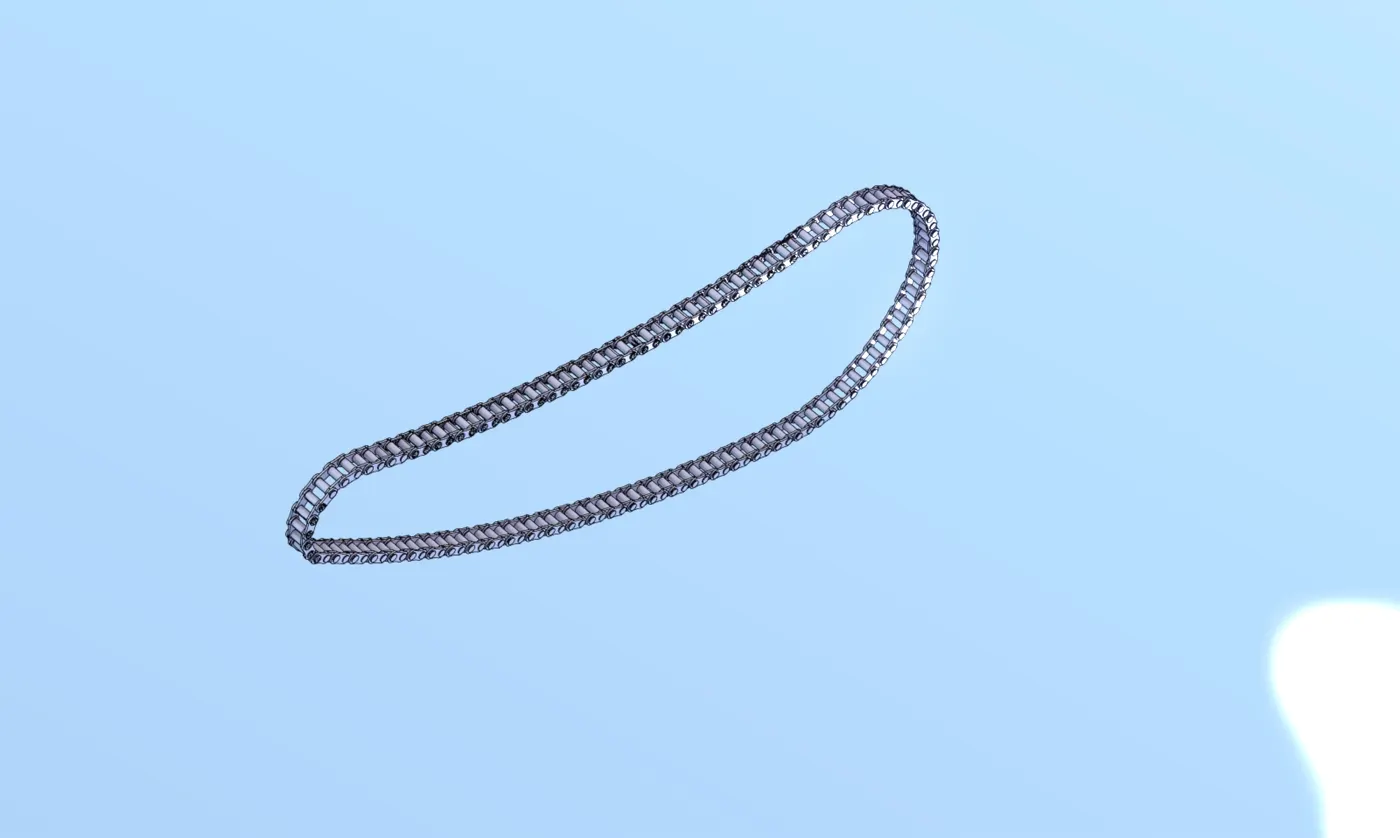
Description: In this part the skecth is intially made to be extrude then the curve driven pattern is proceded.
Pedel
IT is used in foot rest mounted on both side of chassis.
- Extrude
- fillet
- linear pattern

Front wheel
Front wheel is the component which is made more customs modification like spider web rim.
- revolve
- cut extrude
- extrude
- revolve cut
- fillet
- champer
- circular pattern
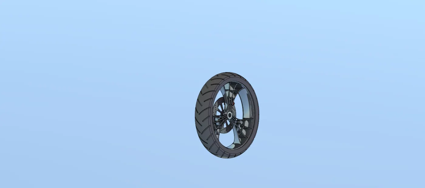
Description: in this part the sketch is initially revolved and extrude cut is made then fillet is made.
Rear wheel
The same process followed in front wheel is repeated with different dimenssion
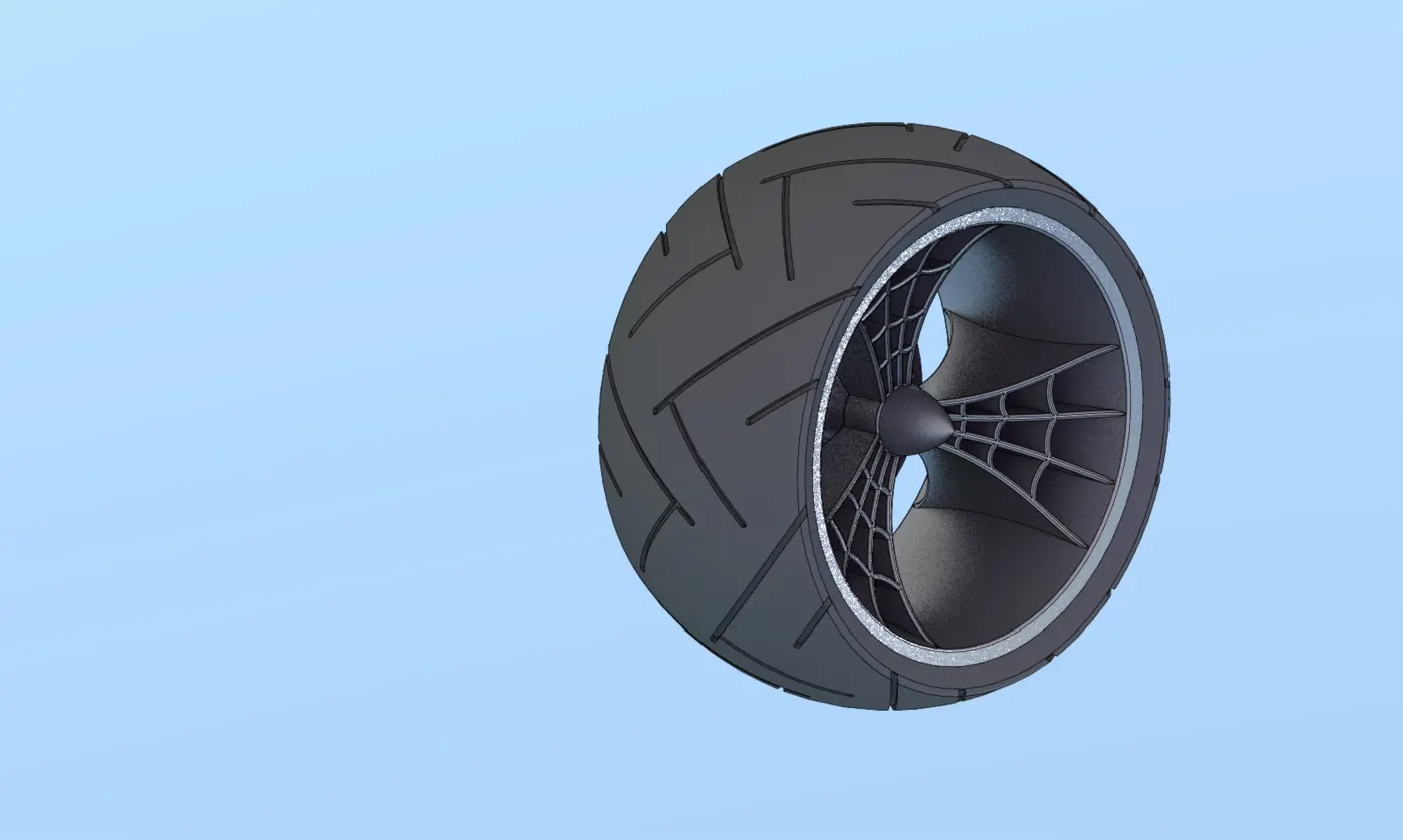
Description: in this part the sketch is initially revolved and extrude cut is made then fillet is made.
Front fork
This component is used in stabilizing and handiling the wheel
- revovle
- boss extrude
- linear pattern
- dome
- cut revolve
- combine
- sweep
- mirror
- project curve
- fillet
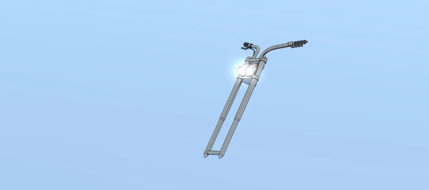
Description: Intially the sketch is revovled and then follwed by boss extrude then continue with linear pattern cut revovle is made then dome is created and then it is made by sweep finally it is combined.
Chassis
chassis is simply known to be skeleton of veichle.
- revovle
- boss extrude
- linear pattern
- dome
- cut revolve
- combine
- sweep
- mirror
- project curve
- fillet
- offset entities
- convert entities
- extrude cut
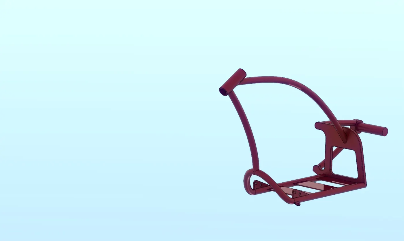
Description: In this part major feature is project curves and sweep and other features are normall as other.
Engine
Engine is known to be the heart of the vechile it is the combustion chamber.
- revovle
- boss extrude
- linear pattern
- dome
- cut revolve
- combine
- sweep
- mirror
- project curve
- fillet
- extrude cut
- circuler pattern
- thin extrude
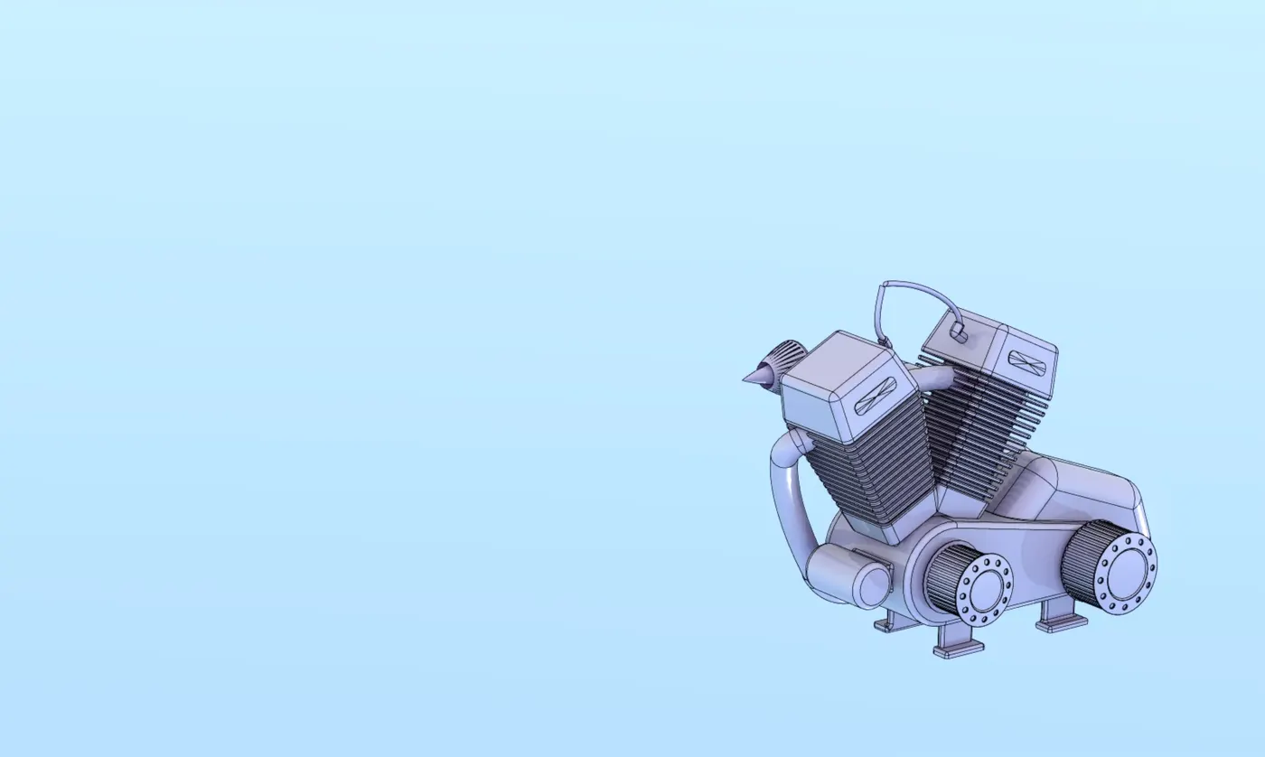
Description: In this part all the features are used from extrude sketches and then project ncurves are made criticall to finish this part and sweep finally fillets are made.
Gas tank
This component is place where fuel is stored is featured by surface modelling.
- surface sweep
- surface trim
- surface loft
- boundary surface
- surface knit
- sweept cut
- fillet
- mirror
- shell
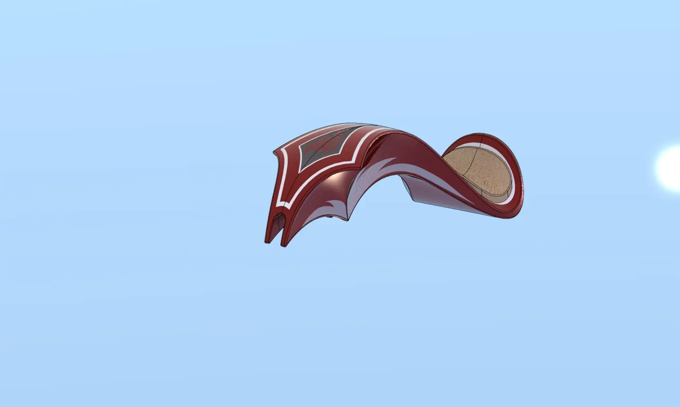
Description : In this part the surface features sre used where intially surface sweep and continued with surface trim and surface loft finally the part is knitted without gap.
Assembly of chopper
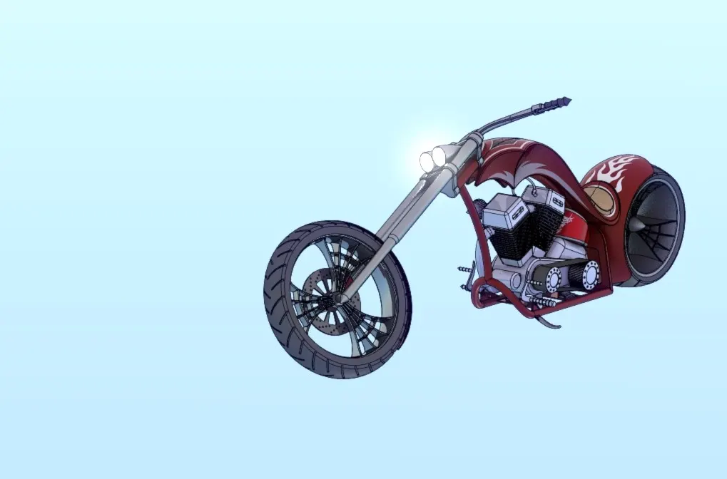
renderd image of chopper front plane:
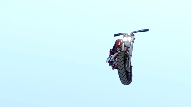
rendered image of top plane chopper:
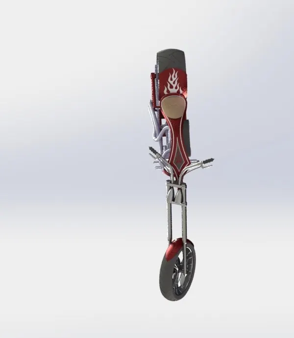
rendred image of right plane:
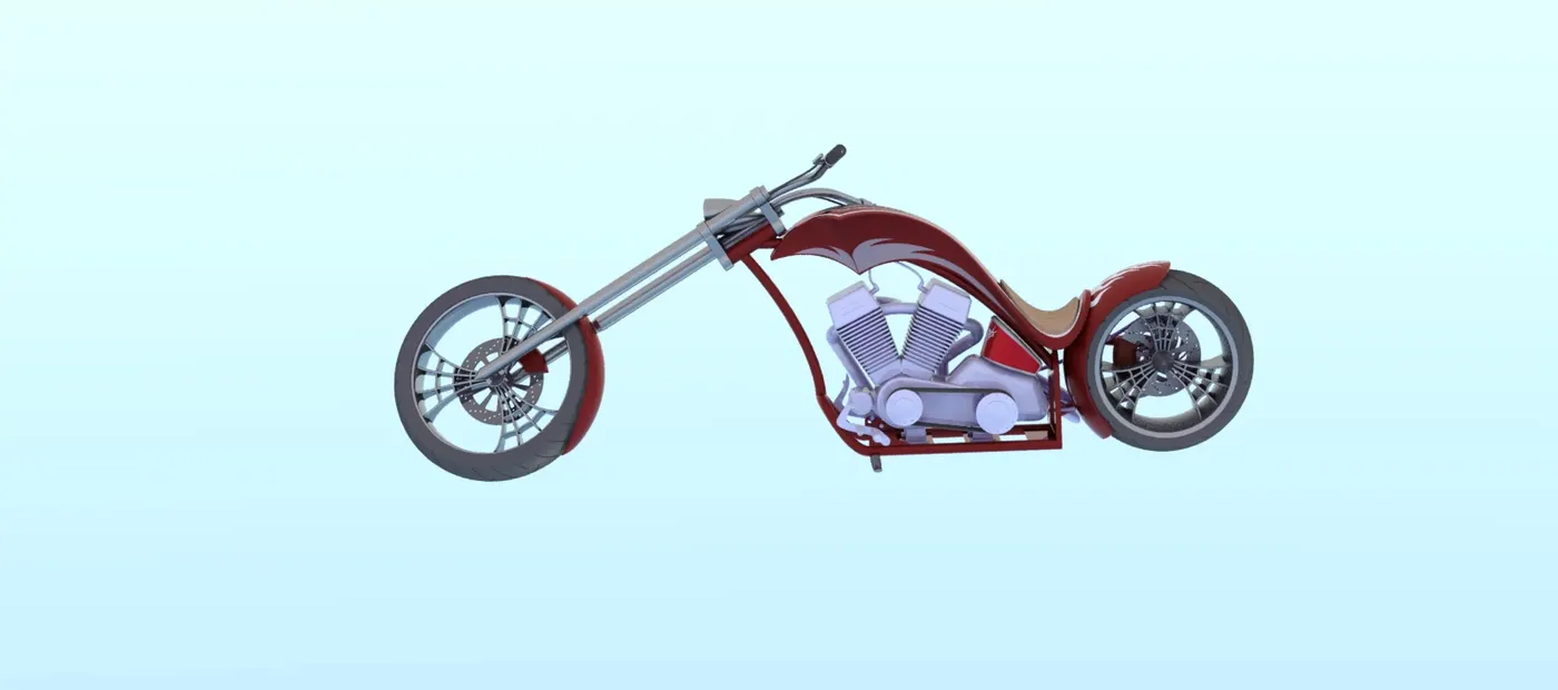
rendered image of isometric view
Conclusion
BY finishing this project i have got many tool knowledge about solid works.