Photo Realistic Rendering
MODELING OF AMERICAN CHOPPER
ON SOLIDWORKS
INTRODUCTION
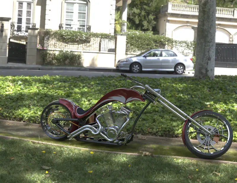
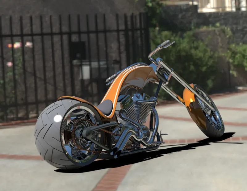
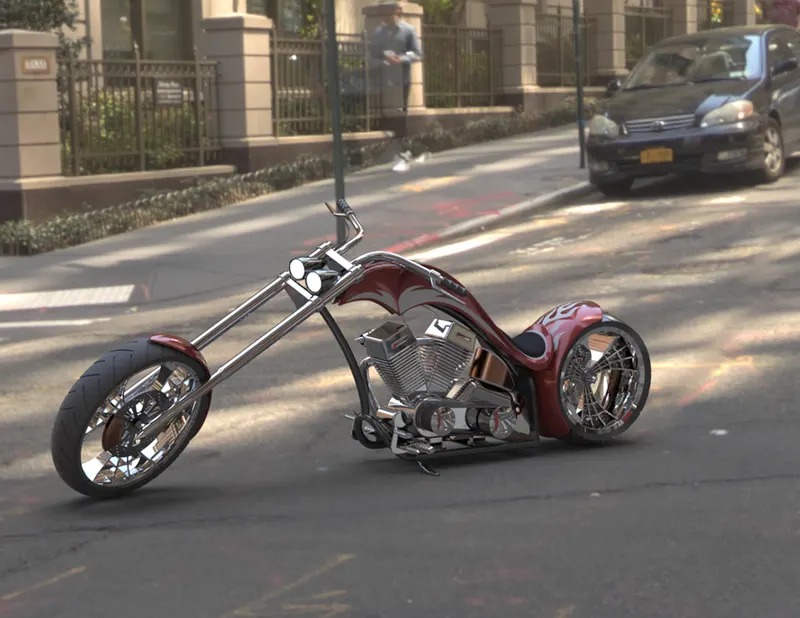
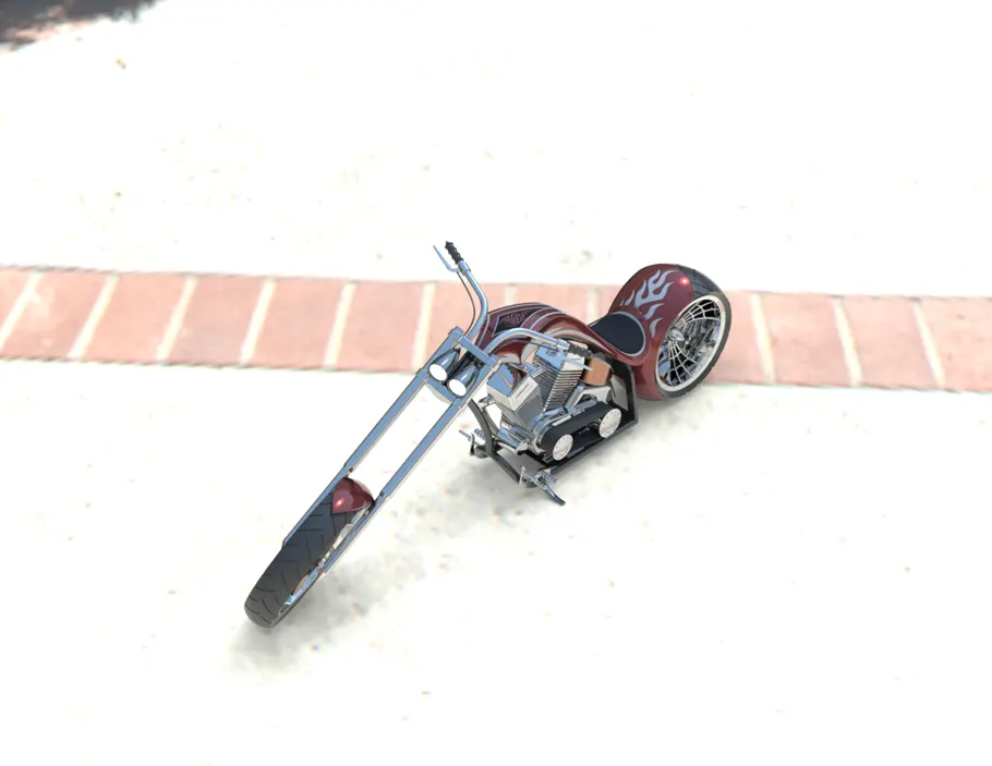
In this project we learn about the American Chopper bike Design and Assembly with the help of Solidworks 2020. In this first we learn commands after that using this commands we draw the sketch of part with the accurate dimension. After completing all part we assemble the American chopper. Then we add the lights, camera, decal to the model and do the rendering of chopper using the solidworks visualization 2020.
Part Of American chopper
- Transmission belt
- Kickstand
- Front and rear fender
- Oil tank and pedal
- Chain
- Front and rear wheel
- Front fork
- Chassis
- Engine
- Gas Tank
Design approach
There is two type of design approach
- Bottom up approach
- Top down approach
Bottom-up Design
Bottom-up design is the traditional method. You first design and model parts, then insert them into an assembly and use mates to position the parts. To change the parts, you must edit them individually. These changes are then seen in the assembly.
Top down approach
In Top-down design, parts' shapes, sizes, and locations can be designed in the assembly
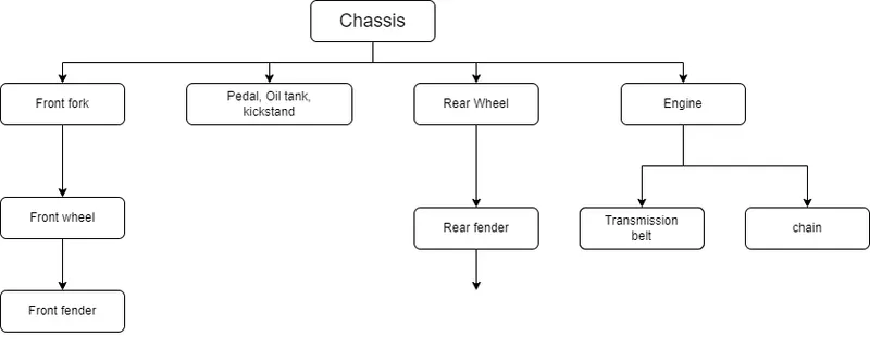
Flowchart
Feature
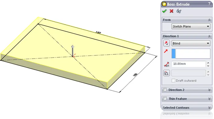
Extrude
Extrude tool is used to extend a sketched profile in one or two directions as either a thin feature or a solid feature. An extrude operation can either add material to a part (in a base or boss) or remove material from a part
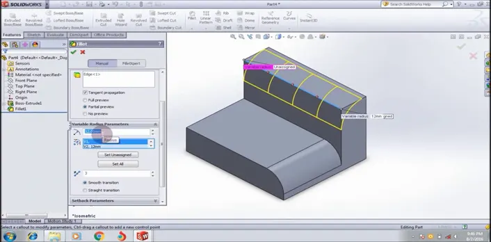
Fillet
Fillet/Round creates a rounded internal or external face on the part. You can fillet all edges of a face, selected sets of faces, selected edges, or edge loops
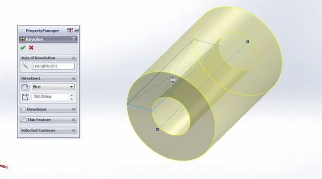
Revolve boss feature
Revolves add or remove material by revolving one or more profiles around a centerline. You can create revolved boss/bases, revolved cuts, or revolved surfaces. The revolve feature can be a solid, a thin feature, or a surface
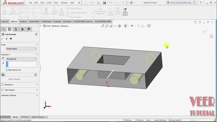
Extrude cut
This is a handy feature to aid in material removal of a 3D model using 2D sketches. We will be taking a deeper dive into the terminology, as well as how to access the feature from different menus.
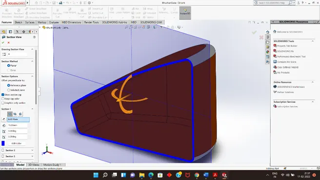
Shell
The shell tool hollows out a part, leaves open the faces you select, and creates thin-walled features on the remaining faces. If you do not select any face on the model, you can shell a solid part, creating a closed, hollow model. You can also shell a model using multiple thicknesses
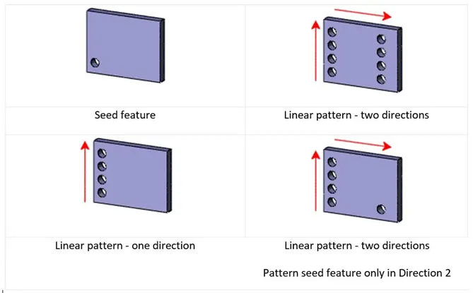
Linear pattern
Use linear patterns to create multiple instances of one or more features that you can space uniformly along one or two linear paths. Create one or more features to replicate
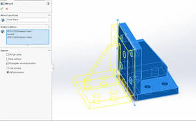
Mirror
Creates a copy of a feature, (or multiple features), mirrored about a face or a plane. You can select the feature or you can select the faces that comprise the feature. Bodies to Mirror. Select a body in a single model or multibody part to create a mirror entity
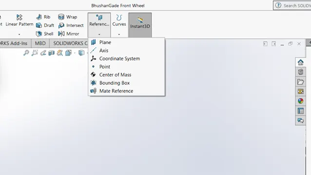
Reference geometry
Reference geometry defines the shape or form of a surface or a solid. Reference geometry includes items such as planes, axes, coordinate systems, and points. You can use reference geometry in the creation of several kinds of features. For example: Planes are used in lofts and sweeps.
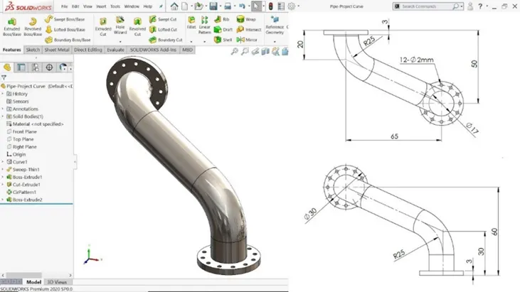
Projected curve
You can project a sketched curve onto a model face to create a 3D curve. You can also create a 3D curve that represents the intersection of two extruded surfaces generated by creating sketches on two intersecting planes. You can also use 3D sketches as input for the Projected Curve tool. ...
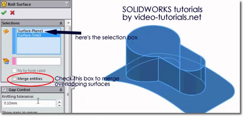
Knit
Use the Knit Surface tool to combine two or more faces and surfaces into one. Create a solid body when the knit surfaces form a closed volume, or leave as a surface body. ... Select Merge entities to merge faces with the same underlying geometry
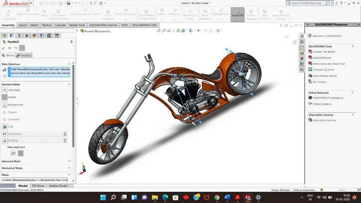
Mate
Mates create geometric relationships between assembly components. As you add mates, you define the allowable directions of linear or rotational motion of the components. You can move a component within its degrees of freedom, visualizing the assembly's behaviour.
This feature include
Parallel: Keeps selected items at a constant distance from each other.
Perpendicular: Places selected items at a 90 degree angle from each other.
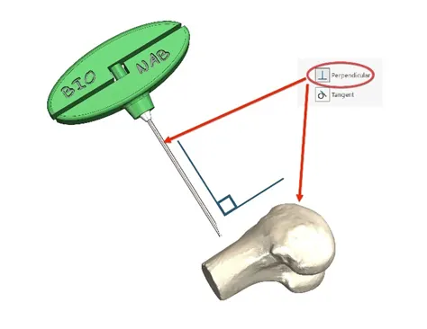
Tangent: Places a cylindrical, spherical, or conical face tangent with another component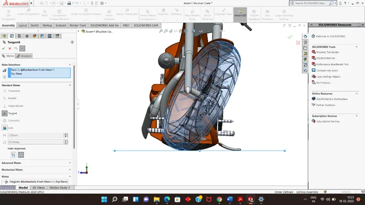
.
Coincident: A coincident mate, like the name sounds, is a mate between two features that you want to coincide with each other. Generally we use it for making two planes parallel and coincident.

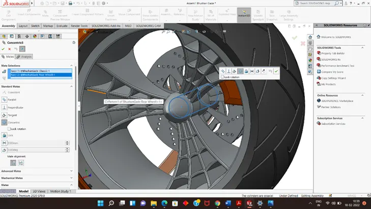
Concentric: A concentric mate forces two cylindrical faces to become concentric. The faces can move along the common axis, but cannot be moved away from this axis.
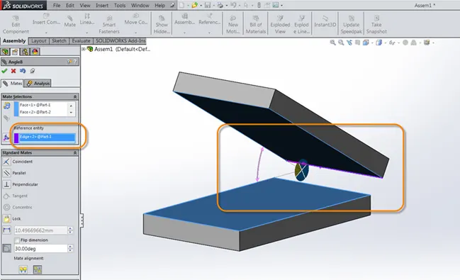
Angle: This makes the mate definition more robust and predictable. To define an angle mate and place the dimension: ... In the Mate Property Manager, under Standard Mates, click Angle. In Mate Selections, select the edges shown for Entities to Mate.
Parts
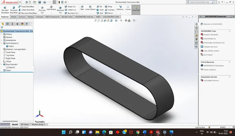
Transmission belt
Transmission belt as a machine component used to transmit the power from one shaft/pulley or rotating component to another These belts are made mostly of Rubber canvas material The transmission belt used in the choppers used to drive the chain shaft driven by the engine By wheel
Features used to create transmission belt
- Sketch
- Extrude
- Offset
- Fillet
- Appearance
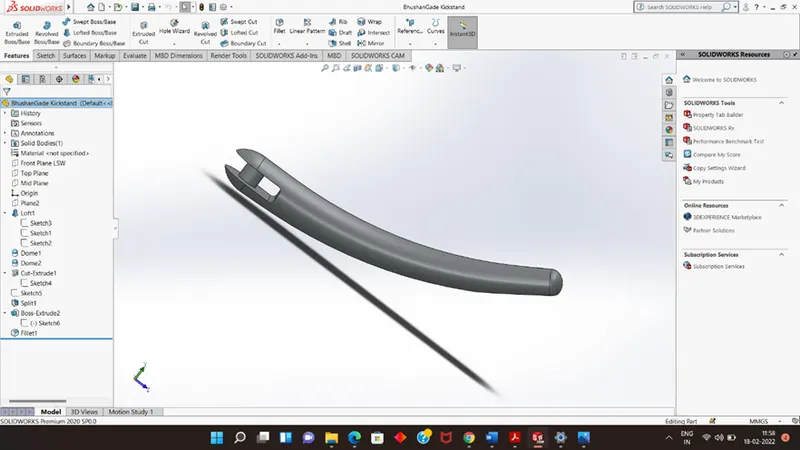
- Kickstand
A kickstand helps to supports a chopper when its parked.
Features used to create kickstand
- Sketch
- Ellipse
- Splines
- Loft
- Cut extrude
- Extrude
- Split
- Fillet
- Appearance
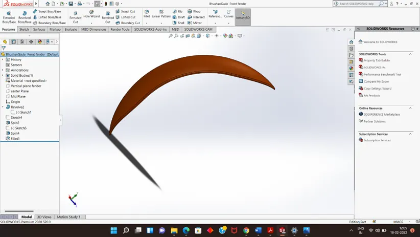
3.Front Fender
Fender is the American English term for the part of an automobile, motorcycle or other vehicle body that frames a wheel well (the fender underside). Its primary purpose is to prevent sand, mud, rocks, liquids, and other road spray from being thrown into the air by the rotating tire.
Features used to create the Front fender:
- Sketch
- 3-point arc
- Trim
- Extend
- Revolve
- Spline
- Fillet
- Appearance
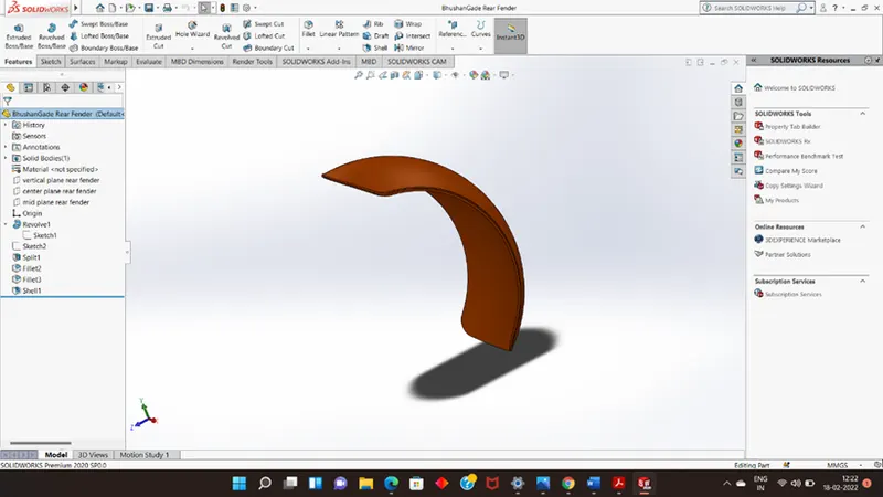
- Rear fender
A Rear fender is an automobile part that is bound to the vehicle frame and is placed as a cover on the upper side of the tyres. Its primary purpose is to prevent sand, mud, rocks, liquids, and other road spray from being thrown into the air by the rotating tire. Rear wheels require the fenders to provide mud and gravel protection on the front side that is, the rider side and the chassis. This part is also known as mud guard.
Features used to create the Rear fender
- Sketch
- 3-point arc
- Extend & trim
- Revolve
- Spline
- Fillet
- Appearance
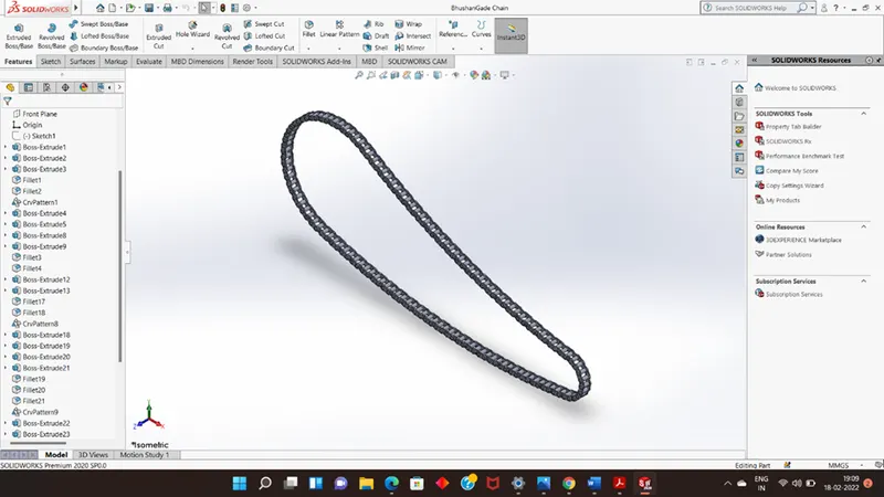
5.Chain
Chain drive is a transmission system its use to transmit power from engine to rear wheel to help running of chopper.
Features used to create the Chain
- Sketch
- Circles
- 3-point arc
- Slot
- Block
- Fillet
- Curve pattern
- Mirror
- Appearance
6.Oil tank
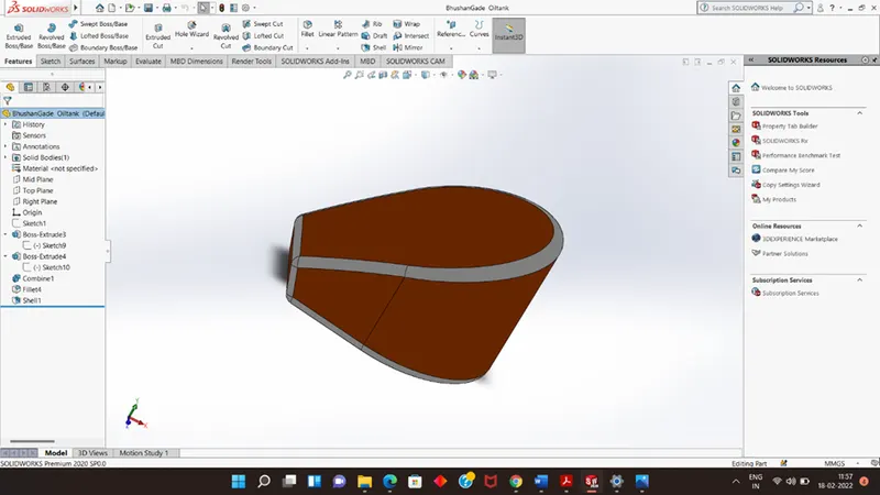
Oil tank is used for containing or storing oil
Features used to create the Oil tank:
- Sketch
- Lines
- 3-point arc
- Extrude
- Combine
- Fillet
- Shell
- Appearance
7.Pedal
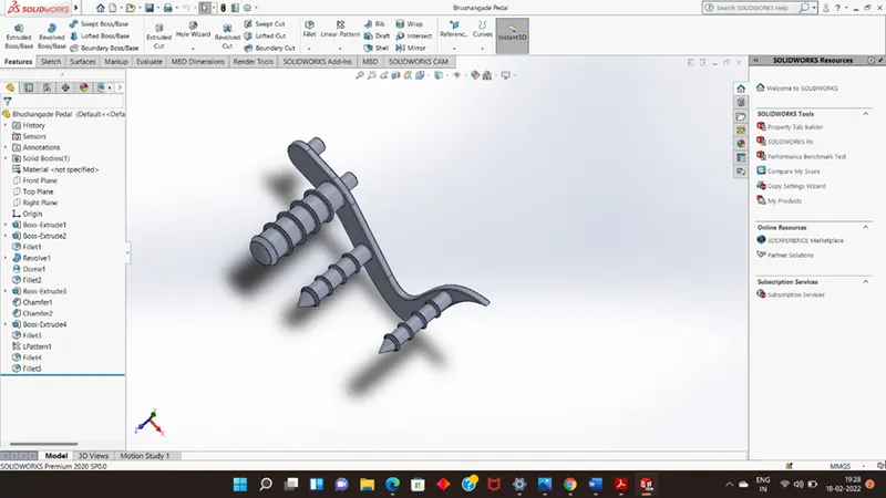
Pedal is the external part attached to the chassis, the pedal is used to place the leg over it and provide comfort to the rider
Features used to create the Pedal
- Sketch
- Lines
- Circles
- Fillet
- Revolve
- offset
- Dome
- Chamfer
- Linear pattern
- Appearance
8.Front Wheel:-
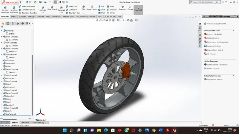
Wheel consists of the rims and the tyre which make it the component that makes connection between the motorcycle and the ground. The rim is an important strength component which ensure safe load carrying capacity of the bike
Front wheel of choppers are always larger than rear wheel
Features used to create the Front wheel
- Sketch
- Lines
- 3-point arc
- Sketch Fillet
- Revolve & revolve cut
- Spline
- Extend & trim
- Cut Extrude
- Offset
- Circular pattern
- Chamfer & fillet
- Appearance
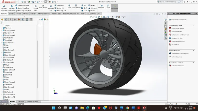
- Rear wheel
Rear wheel is situated at rear portion of chassis. the rear wheel consists rim, sprocket, calliper, tyre, and disc. The power is transmitted to rear wheel from engine to the wheel through the chain
Features used to create the Rear wheel
- Sketch
- Lines
- 3-point arc
- Sketch fillet
- Revolve &revolve cut
- Spline
- Extend & Trim
- Extrude & extrude cut
- Offset
- Circular pattern
- Chamfer and fillet
- Appearance
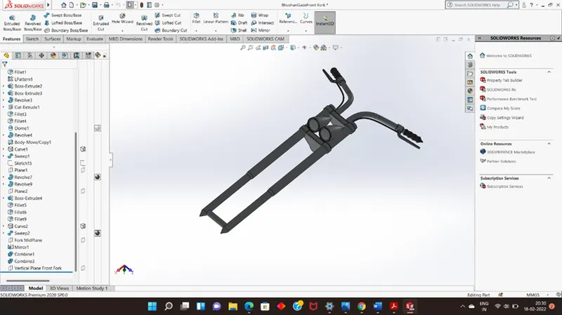
- Front Fork-
A motorcycle fork is a component that connects the front wheel of the bike to the frame of the motorcycle. It is used as part of the steering mechanism that allows the user to turn the front wheel, and in most cases, it is used as a shock absorption system.
Features used to create the Front fork
- Sketch
- Lines and circles
- Revolve
- Fillets
- Linear pattern
- Spline and projected curves
- Cut extrude
- Dome
- Sweep
- Reference plane
- Mirror and combine
- Appearance
- Chassis:-
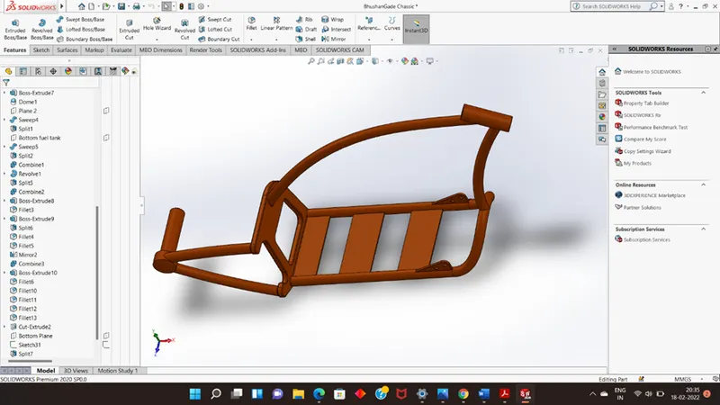
A motorcycle's chassis or frame forms its skeleton. All the components of a motorcycle, like the suspension, wheels, fuel tank, seats, handlebars etc, are attached to this base structure which lends a motorcycle its strength and ability to handle well.
Features used to create the Chassis
- Blueprint sketch
- Spline & projected curves
- Mirror
- Extrude & cut extrude
- Chamfer
- Dome
- Split
- Revolve
- Combine
- Appearance
12.Engine
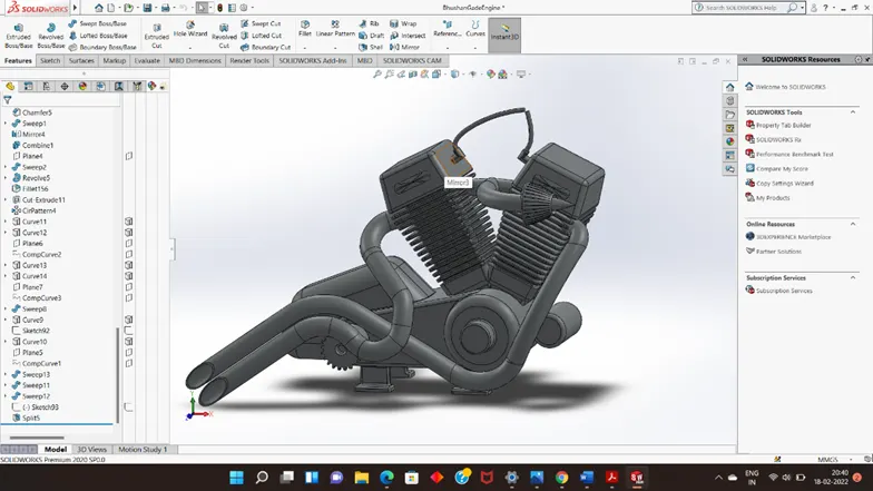
The engine is the prime mover of the vehicle, the engine converts the chemical energy into heat energy and then the heat is converted into mechanical energy, that power from engine is transmitted to rear wheel through gear box and chain sprocket mechanism
Features used to create the Engine
- Blueprint Sketch
- Lines & circles
- Extrude & cut extrude
- Fillet & chamfer
- Revolve
- Dome
- Circular and linear pattern
- Mirror
- Projected and composite curves
- Split
- Appearance
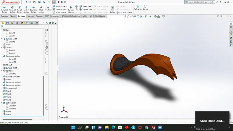
13.Gas tank
Gas tank is the fuel storage component of the motorcycle. It is made to store flammable gas in a cool and state away from the engine heat. Safety of the gas is the main criteria in designing the gas tank.
Features used to create the Gas tank
- Blueprint sketch
- Surface sweep
- Surface trim
- Surface boundary
- Surface loft
- Spline & curve
- Mirror
- Surface knit
- Surface extrude
- Shell & fillet
- Extrude cut
- Appearance
Assembly of the Chopper
Assembly Definition An assembly is a collection of related parts saved in one SOLIDWORKS document file with a .SLDASM extension
Initially, the chassis part is inserted in the assembly by using insert part in the option, after that the part is inserted in the assembly environment fix it. and the other parts of the chopper are inserted into the assembly and given possible mate condition
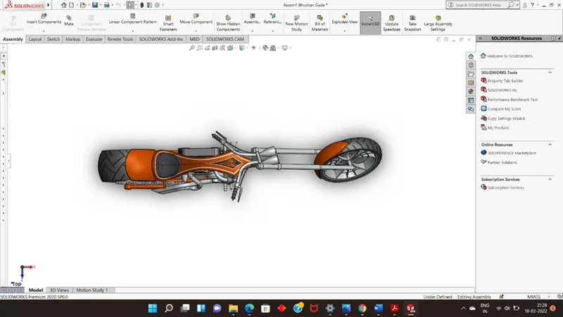
Top View
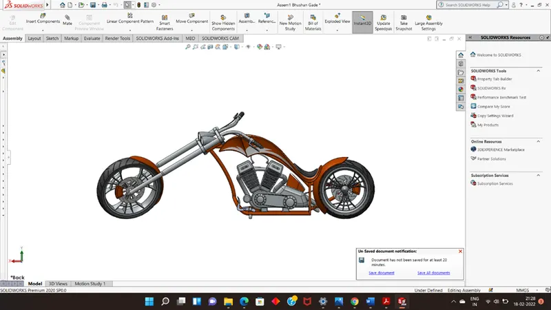
Right View
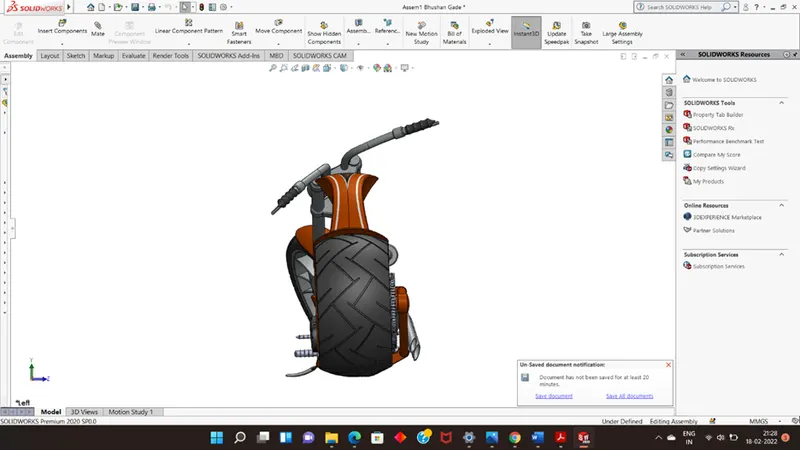
Back view
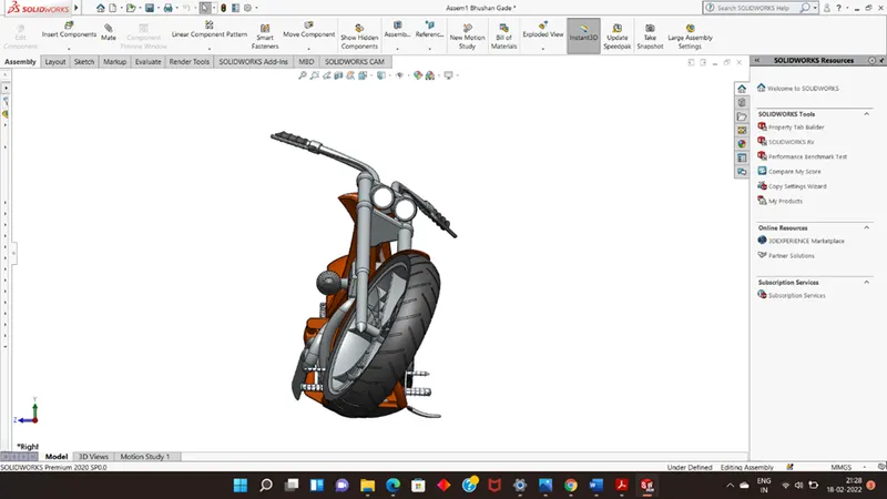
Front VieW
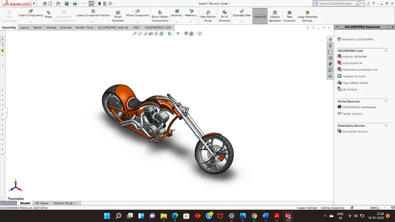
Isometric View
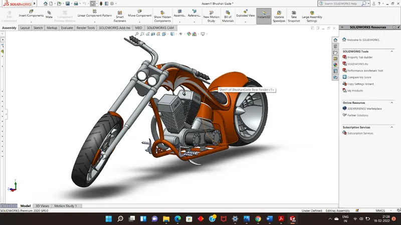
Front View of chopper
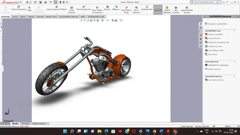
Camera view
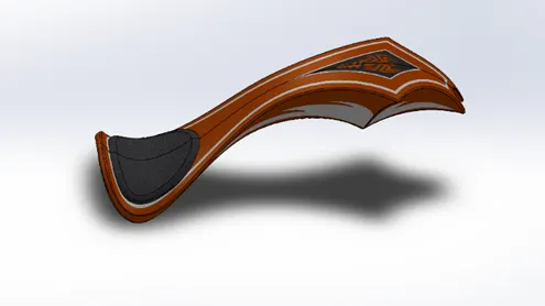
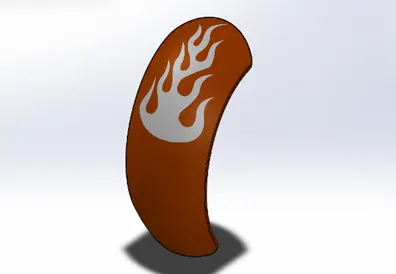
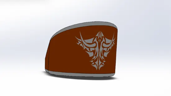
Decals
A decal is a 2D image applied to a model. ... You can use decals to create model details that you can represent with an image instead of with the model geometry, such as a car grill or a picture frame. You can view and apply decals in SOLIDWORKS. You can view decals in eDrawings and PhotoView 360
Rendering
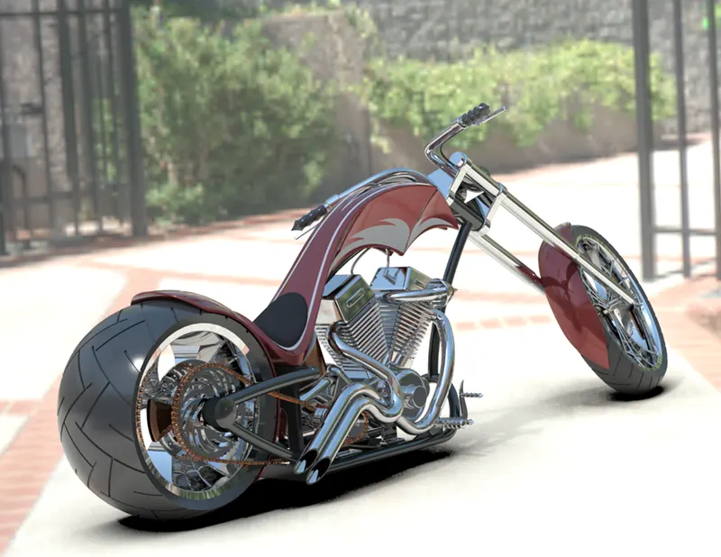
PhotoView 360 is a SOLIDWORKS add-in that produces photo-realistic renderings of SOLIDWORKS models. The rendered image incorporates the appearances, lighting, scene, and decals included with the model.
Rendering of the assembly is done to make a good quality 2D images for the purpose of advertising and promotion of the products before selling it to the customers. Photorealistic rendering creates high quality images or motion graphics if available so as to look appealing in various environments and backdrops
Solidworks provides 2 rendering products:
- Photoview 360 which is inbuilt add in for Solidworks
- Solidworks Visualize which is a separate Render Engine
Thank you