American chopper bike
AMERICAN CHOPPER
Objective
To model American chopper and make a photorealistic rendering of the model using solidworks.
Method
Types Of Commands
Sketch: Create the 2D or 3D sketches and dimension and apply geometrical relations.
Features: Select the appropriate features such as revolve, extrudes and fillets, determine features to apply.
Surfaces: Surfaces are formed by applying various surface features like extrude thin.
Assembly: Select the components to mate and apply the mates.
Sketch Creating a model begins with a sketch. Based on the sketch, we can create features. We can add delete or combine one or more features to make a part. Then, we can mate the appropriate parts to create an assembly. From the parts or assemblies complete drawings are created.
3-D sketch When sketching in 3D, we can snap to directions X, Y, and Z, and constraints are applied Along X, Y, Z respectively. When sketching on a plane, we can snap to the horizontal or vertical directions in the plane, and constraints are applied to the Horizontal and the Vertical.
1.Sketch Commands
Smart Dimension - Creates a geometrical dimension for any selected sketch entity.
Point – It is a 1D element, it inserts a point or vertex into a sketch entity. This cannot be deleted if it is part of sketch endpoint or centre point.
Line - Line is one of the first sketching tools, lines can be drawn horizontally, vertically or at any angle. It plays very important role to complete the 2D drawing of the product or part and very easy to utilize its features.
Circle - The circle enables to create the circular drawing on the graphics area. There are two circle tools are available and they are “Centre circle” and “Perimeter circle”.
Rectangle - Sketches rectangles or square with a centre point at a selected angle there are rectangles like centered rectangle, corner rectangle. Parallelogram sketches a standard parallelogram.
Spline – splines can be created with number of midpoints depending upon the complexity of the curve. A 2or 3 dimensional curves defined by a set of control points. Points within a spline can be added or deleted.
Sketch Fillet - A tangent arc in between two sketch entities can be created with a radius.
Text - It can be used to write the text necessary wherever required either it’s a plane or face of a model.
Convert Entities - Copy a sketch entity on plane, it must have an original sketch entity already drawn and selected to use this tool.
Offset Entities – Creates a sketch entity to a specified distance from the original entity. Must have an original sketch entity already drawn and selected to use this tool.
Sketch Picture - Insert an image file into the background of a sketch. This allows the user to 2D sketches based on the image. Use the sketch picture property manager to alter the inserted image.
2.Features
Some sketch-based features are shapes such as extrude, extrude-cut and holes. Other sketch-based features such as lofts and sweeps use a profile along a path. Applied features include fillets, chamfers, or shells they are applied to existing geometry using dimensions and other characteristics to create the feature. Then we add applied features. It is possible to create a part without sketch-based features.
Feature Commands
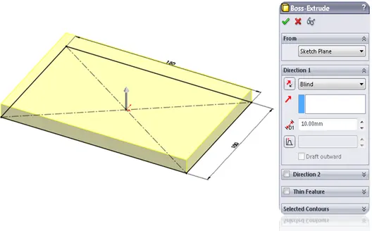
Extruded Boss/Base - An Extruded Boss/Base feature will allow us to take a 2D sketch and add thickness to it in the perpendicular dimension.
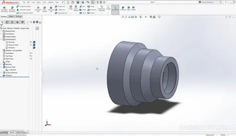
Revolve – Creates a revolved solid from a sketch about an axis.
Extruded Cut – It is a tool to remove material by projecting a sketched section normal to the sketch plane.
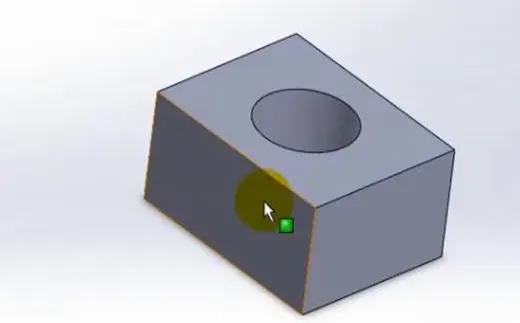
Combine – Combines the solids based on add, subtract and common areas are present.
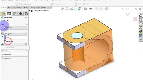
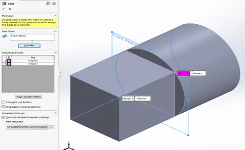
Split - Lines are used to divide model faces into two. Split lines are created like any other sketched feature. They can be one or more connected sketch entities. They must be oriented so that they will pass through model faces when projected normal to the sketch plane.
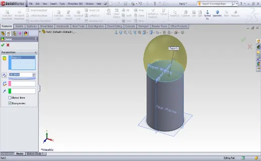
Dome – dome can be of two types elliptical and spherical. It can add one or more domes to the selected planar or non-planar faces. The software calculates the distance using the radius of the arc as a basis for the dome.
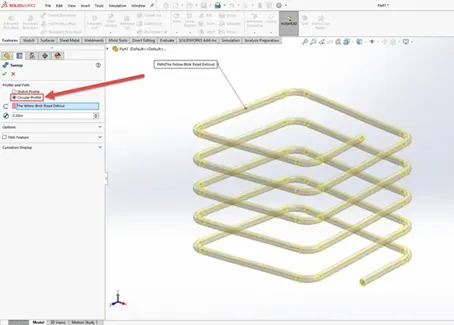
Pierce Relationships - The Pierce relationship is used to sweep along a path. It can be thought of as a 3D Coincident relationship. In our spring, the circle will follow the helix. Consider the helix as a thin piece of wire and the profile sketch as being drawn on a piece of paper. If we stick the wire through the paper at the centre of the circle, this would be a pierce relationship. When we perform the sweep, the paper will slide along the wire, held at the pierce point.
Merge – combines solids or surfaces directly as a single solid or surface.
Modelling
The American chopper consists of following parts to be assembled
1.Chassis
2.Engine
3.Front Fork
4.Pedal
5.Chain
6.Oil tank
7.Gas tank
8.Transmission Belt
9.Front fender
10.Rear fender
11.Front wheel
12.Back Wheel
13.Kick Stand
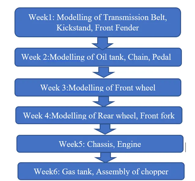
The parts have been modelled as per the dimensions in the weekly video course.
Week1: Transmission belt, Kick stand, Front fender
Commands used: 2D Sketches, Lines, Circles, Splines, Smart dimensioning, Extrude, Dome, Revolve, Fillets and materials are applied accordingly as shown in the solid works course.
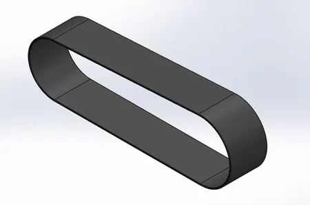
Fig1: Transmission Belt
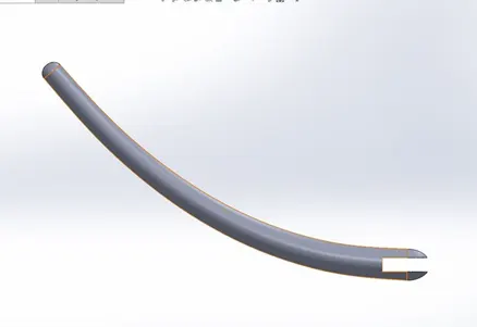
Fig2: Kickstand
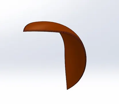
Fig3: Front fender
Week 2: Oil tank, Chain, Pedal
Commands used: 2D sketches, lines, circles, splines, smart dimensioning, extrude,11, fillets and materials are applied accordingly as shown in the solid works course.
Two separate bodies are created for oil tank and combined for the common section.
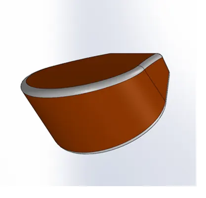
Fig4: Oiltank
For chain, links are created and patterned over the path.
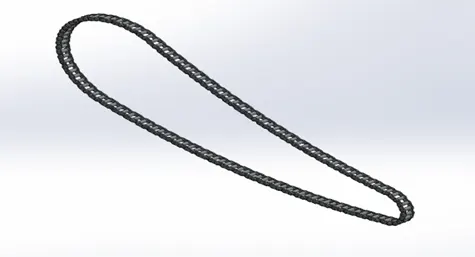
Fig5: Chain
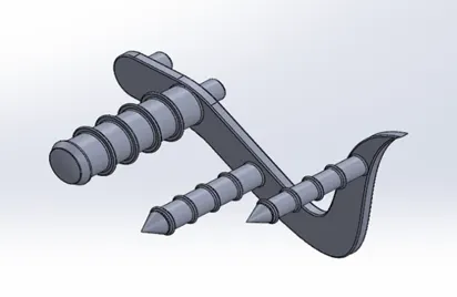
Fig6: Pedal
Week 3: Front wheel
Commands used: 2D sketches-lines, rectangles, circles, splines, smart dimensioning, extrude, extrude cut, convert entities, circular pattern sweep, combine, revolve, fillets and materials are applied accordingly as shown in the solid works course.
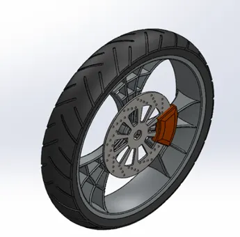
Fig7: Frontwheel
Week 4: Rear wheel, Front fork
Commands used: 2D sketches-lines, rectangles, circles, splines, projected curves, smart dimensioning, sweep, extrude, mirror, extrude cut, convert entities, circular pattern sweep, combine, revolve, fillets and materials are applied accordingly as shown in the solid works course.
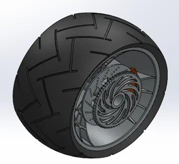
Fig8: Rear wheel
Projected curves are used for front fork for better Design.
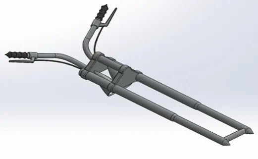
Fig9: Frontfork
Week5: Chassis, Engine
Commands used: 2D sketches-lines, rectangles, circles, splines, smart dimensioning, extrude, extrude cut, sweep, split, convert entities, linear pattern, sweep, chamfer, fillets and materials are applied accordingly as shown in the solid works course.
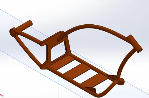
Fig10: Chassis
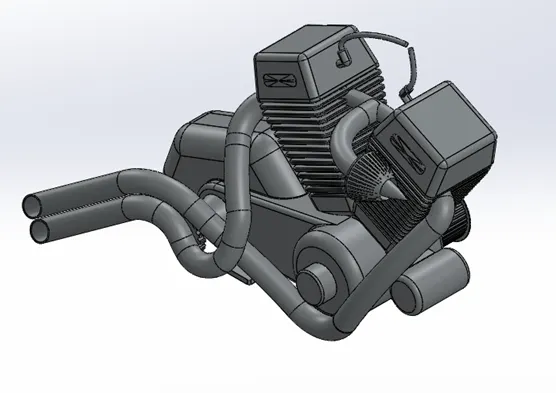
Fig11: Engine
Week6: Gas tank
Commands used: 2D sketches-lines, rectangles, circles, splines, smart dimensioning, extrude cut, convert entities, surface sweep, surface loft, Knit, fillets and materials are applied accordingly as shown in the solid works course.
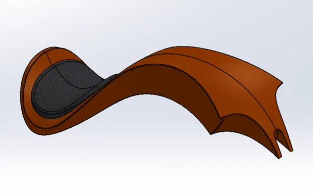
Fig12: Gas tank
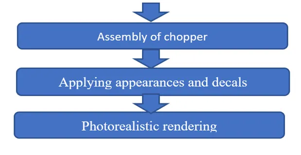
Assembly
Using mating of surfaces planes and some entities the assembly of the all above parts is done using with respective parts with final reference to fixed chassis and decals have been adjusted onto various parts.
Mates: Parallel mates, width mates, limit angle mates, distance mates, concentric mates, tangent mates, coincident mates, angle mates.
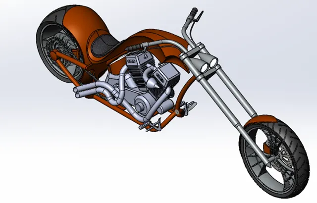
Fig13: Chopper Assembly
Rendering
The photoview 360 rendering is done in solidworks to obtain realistic views and various views have been rendered by adjusting the lightings according to scene.
Decals provide us option to apply logos and allows labelling on surfaces.
Appearances allow us to apply paintings of colours on bodies, parts, or surfaces.
Lightings can be adjusted in the scene or assembly to match the environment and look real
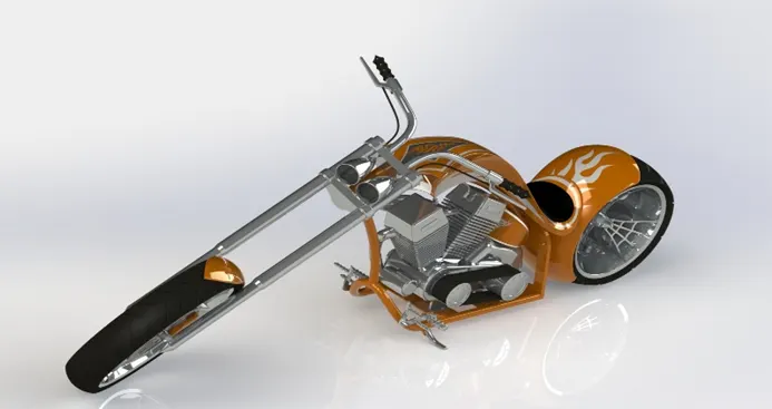
Fig14(a): Rendered bike
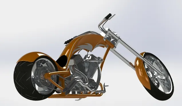
Fig14(b): Rendered bike
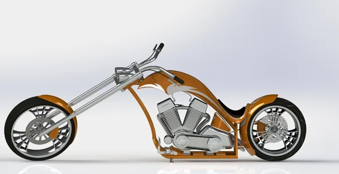
Fig14(c): Rendered bike
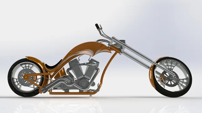
Fig14(d): Rendered bike
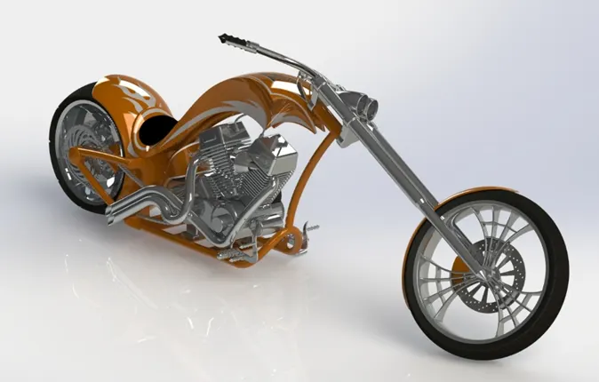
Fig14(e): Rendered bike
Conclusion:
The American chopper has been modelled and rendered using solid works design software.