Boeing-747
Boeing 747
Objective
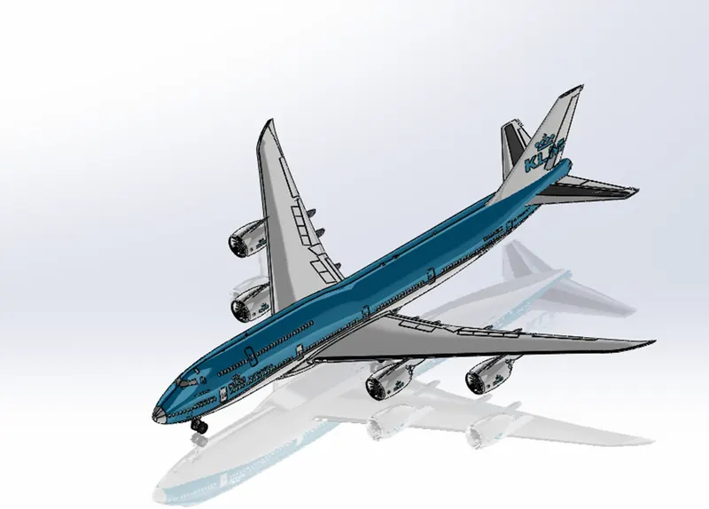
To model Boeing – 747 model by parts, assemble it and make a photorealistic rendering of the model using solidworks.
Methodology
Types Of Commands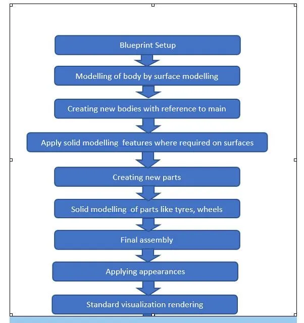
Sketch: Create the 2D or 3D sketches and dimension and apply geometrical relations.
Features: Select the appropriate features such as revolve, extrudes and fillets, determine features to apply.
Surfaces: Surfaces are formed by applying various surface features like extrude thin.
Assembly: Select the components to mate and apply the mates.
Sketch Creating a model begins with a sketch. Based on the sketch, we can create features. We can add delete or combine one or more features to make a part. Then, we can mate the appropriate parts to create an assembly. From the parts or assemblies complete drawings are created.
3-D sketch When sketching in 3D, we can snap to directions X, Y, and Z, and constraints are applied Along X, Y, Z respectively. When sketching on a plane, we can snap to the horizontal or vertical directions in the plane, and constraints are applied to the Horizontal and the Vertical.
1.Sketch Commands
Smart Dimension - Creates a geometrical dimension for any selected sketch entity.
Point – It is a 1D element, it inserts a point or vertex into a sketch entity. This cannot be deleted if it is part of sketch endpoint or centre point.
Line - Line is one of the first sketching tools, lines can be drawn horizontally, vertically or at any angle. It plays very important role to complete the 2D drawing of the product or part and very easy to utilize its features.
Circle - The circle enables to create the circular drawing on the graphics area. There are two circle tools are available and they are “Centre circle” and “Perimeter circle”.
Rectangle - Sketches rectangles or square with a centre point at a selected angle there are rectangles like centered rectangle, corner rectangle. Parallelogram sketches a standard parallelogram.
Spline – splines can be created with number of midpoints depending upon the complexity of the curve. A 2or 3 dimensional curves defined by a set of control points. Points within a spline can be added or deleted.
Sketch Fillet - A tangent arc in between two sketch entities can be created with a radius.
Text - It can be used to write the text necessary wherever required either it’s a plane or face of a model.
Convert Entities - Copy a sketch entity on plane, it must have an original sketch entity already drawn and selected to use this tool.
Offset Entities – Creates a sketch entity to a specified distance from the original entity. Must have an original sketch entity already drawn and selected to use this tool.
Sketch Picture - Insert an image file into the background of a sketch. This allows the user to 2D sketches based on the image. Use the sketch picture property manager to alter the inserted image.
2.Features
Some sketch-based features are shapes such as extrude, extrude-cut and holes. Other sketch-based features such as lofts and sweeps use a profile along a path. Applied features include fillets, chamfers, or shells they are applied to existing geometry using dimensions and other characteristics to create the feature. Then we add applied features. It is possible to create a part without sketch-based features.
Feature Commands
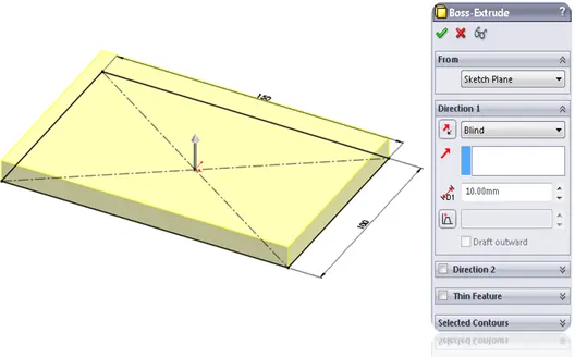
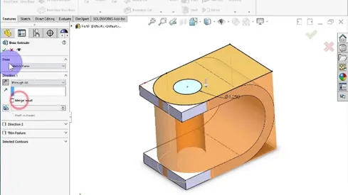
Extruded Boss/Base - An Extruded Boss/Base feature will allow us to take a 2D sketch and add thickness to it in the perpendicular dimension.
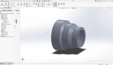
Revolve – Creates a revolved solid from a sketch about an axis.
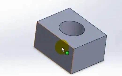
Extruded Cut – It is a tool to remove material by projecting a sketched section normal to the sketch plane.
Combine – Combines the solids based on add, subtract and common areas are present.
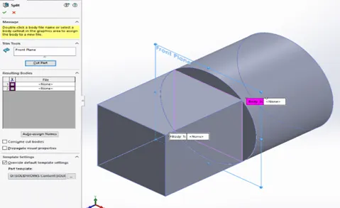
Split - Lines are used to divide model faces into two. Split lines are created like any other sketched feature. They can be one or more connected sketch entities. They must be oriented so that they will pass through model faces when projected normal to the sketch plane.
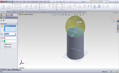
Dome – dome can be of two types elliptical and spherical. It can add one or more domes to the selected planar or non-planar faces. The software calculates the distance using the radius of the arc as a basis for the dome.
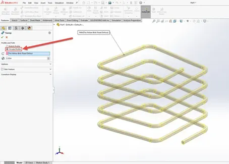
Pierce Relationships - The Pierce relationship is used to sweep along a path. It can be thought of as a 3D Coincident relationship. In our spring, the circle will follow the helix. Consider the helix as a thin piece of wire and the profile sketch as being drawn on a piece of paper. If we stick the wire through the paper at the centre of the circle, this would be a pierce relationship. When we perform the sweep, the paper will slide along the wire, held at the pierce point.
Merge – combines solids or surfaces directly as a single solid or surface.
3.Surface Modelling
zero thickness geometry is known as surface. Surface modelling is a method of creating planar or non-planar complex geometry which has zero or negligible thickness. The surfaces are generally used to create models of complex shapes. We can convert surface models into solid models. We can also extract a surface from a solid model using the tools available for surface modelling.
Surface Commands:
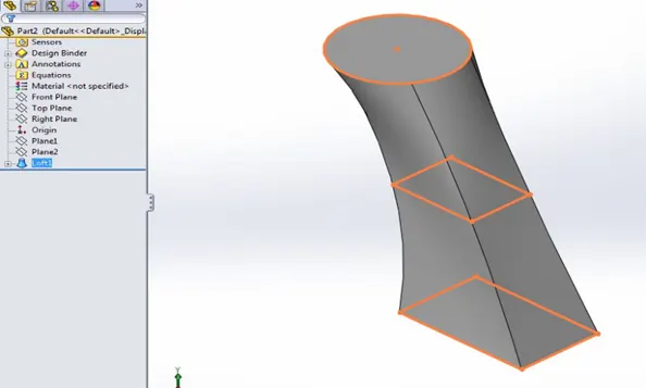
Lofted Surfaces – Creates a lofted surface between two or more profiles or sketches. Specify start and end constraints and add guide curves to specify the path shape.
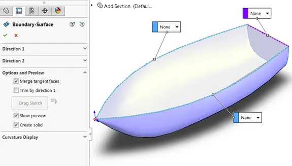
Boundary Surfaces – The boundary surface feature allows to create surfaces that can be tangent or curvature continuous in both directions.
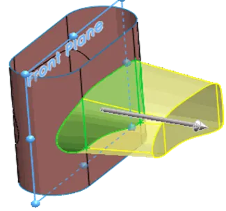
Extruded Surfaces – Extrudes a sketch or selected sketch contours in one or two directions two create a surface features.
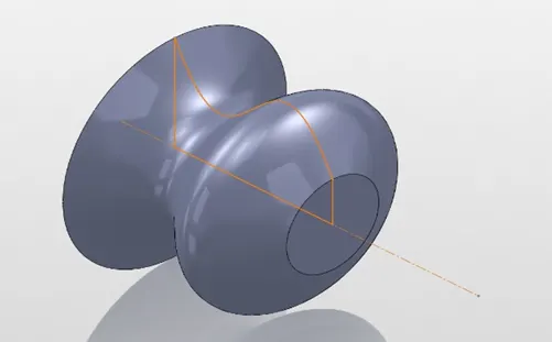
Revolved Surfaces – Revolves a sketch or selected sketch contours around an axis to create a revolved surface features.
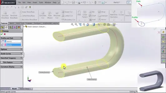
Swept Surfaces – It Sweeps a closed profile along an open or closed path to create a surface feature. It uses a tangent plane at the end of the path so that the path is normal to the swept surface.
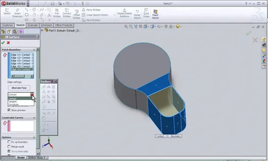
Filled Surfaces – Patches a surface within a boundary defined by edges, sketches, or curves.
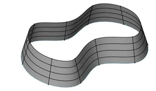
Ruled Surfaces – Inserts ruled surfaces in a specified direction from edges. Tangent to surface, Normal to surface, tapered to vector, perpendicular to vector or sweep can be selected.
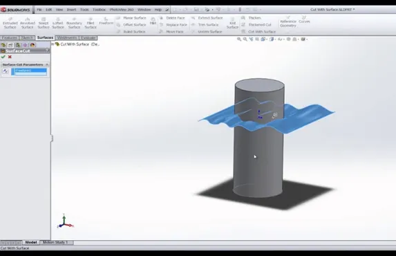
Trim Surface – It trims the surfaces where a surface intersect with another surface, a plane or a sketch.
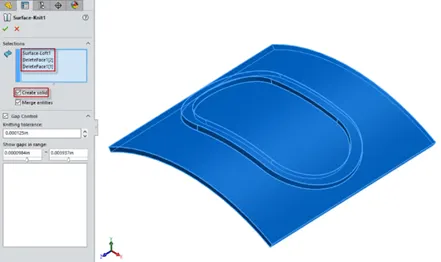
Knit Surface – It combines two or more adjacent, non-intersecting surfaces into a single surface body. The surfaces must join at an edge. If the resulting knit surface encloses a volume and can create a complete solid body.
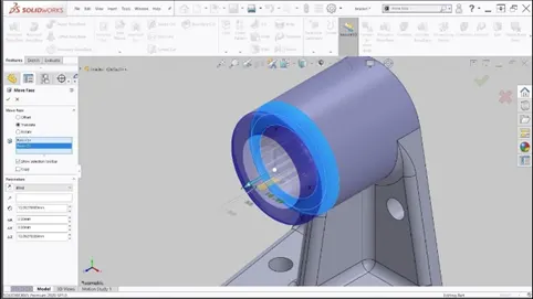
Move/copy surfaces – Moves or copy surfaces about a plane or a sketch.
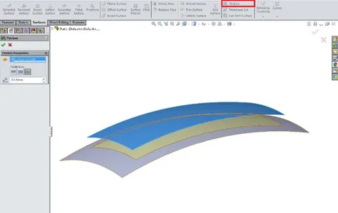
Offset Surface – Offsets surfaces using one or more continuous faces. This tool helps us to create an offset surface with gaps.
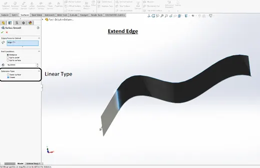
Extend Surface – Extends one or more edges or faces on a surface, based on end conditions and extension type.
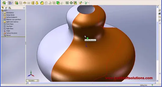
Mirror surfaces – A mirror feature is a copy of a selected feature, mirrored about a plane or planar face. A mirror sketch entity is a copy of a selected sketch entity that is mirrored about a centreline. If the original feature or sketch is modified, the mirrored copy is updated to reflect the change.
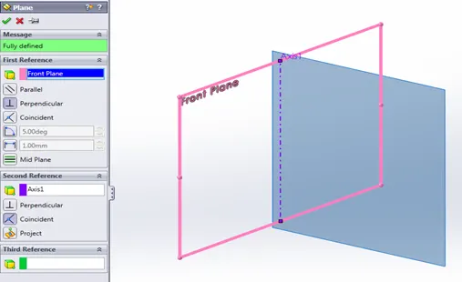
Reference plane – Planes can be created in part or assembly documents. We can use planes to sketch, to create a section view of a model, for a neutral plane in a draft feature, and so on.
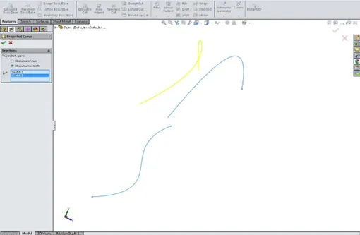
Projected curve – A projected curve is typically used either in sweeps and lofts as path or guide curve.
There are two types of projected curves:
Sketch on Sketch: Use two sketches to make a single curve
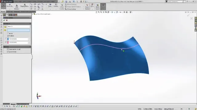
Sketch on surface: Use a sketch to project on a surface.
Modelling
Blueprint setup
Fuselage
Belly Fairing
Nose Cone
Pitot Tubes
Cockpit Windows
Windshield Wipers
Passenger Windows
Doors and Hatches
Lights & Antennas
Auxiliary Power Unit
Vertical Stabilizer & Horizontal Stabilizer
Wing, Flaps & Ailerons
Flap Track fairings
Hatches Closed & Hatches Opened
Wheels
Nose Gear Base, Suspension Arm & Assembly
Main Gear Base, Suspension Arm & Assembly
Engine
Livery
Assembly
- BLUEPRINT
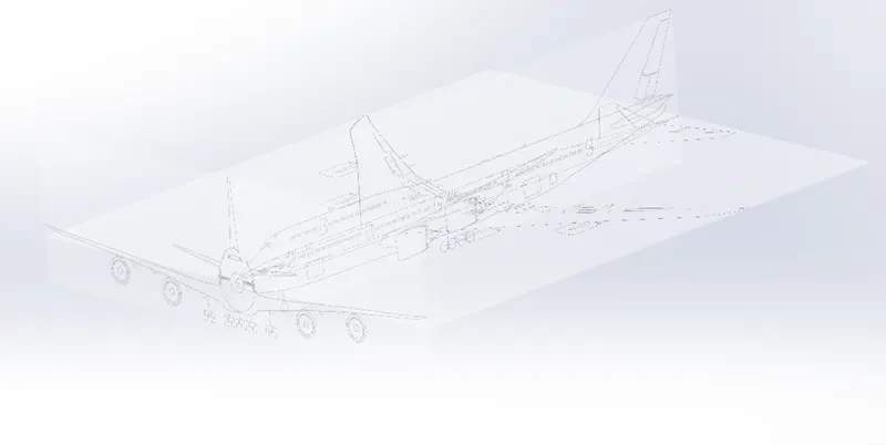
The blueprint pictures are inserted to draw the sketches lines, splines, polygons, convert and trim entities dimensions . They are also used as a reference for modelling.
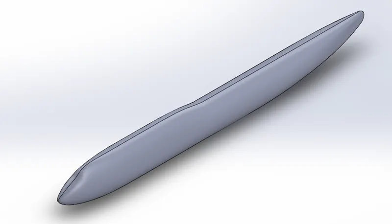
Fuselage
It is used to carry passenger or loads, it is created using surface loft by drawing different sketches on different planes and mirrored on right plane and a sloid feature is applied later converted into a shell.
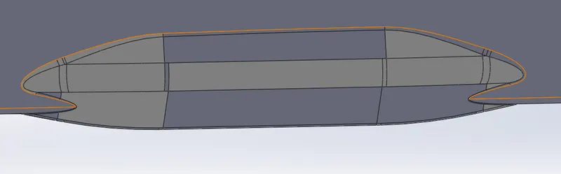
Belly fairing
Belly fairing provides spaces for landing gears and additional cargo created and combined with fuselage.
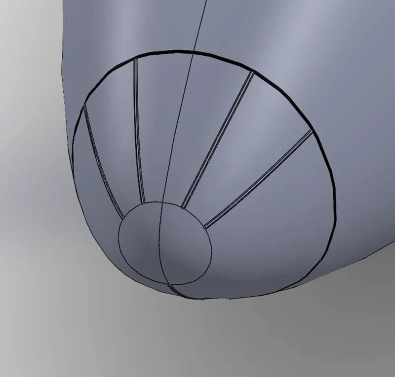
Nose cone
It is created to reduce the drag on the aircraft and created using splitlines thereafter creating a sweep profile.
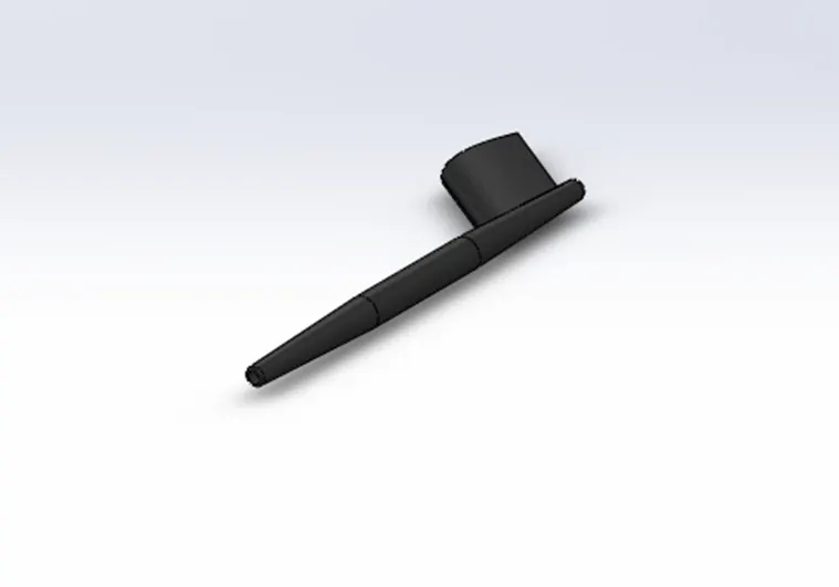
Pitot Tubes This measures the fluid flow velocity and determines the airspeed on an aircraft. It is created using solid modelling features like revolve, sweep and mirrored to other side.
Cockpit windows
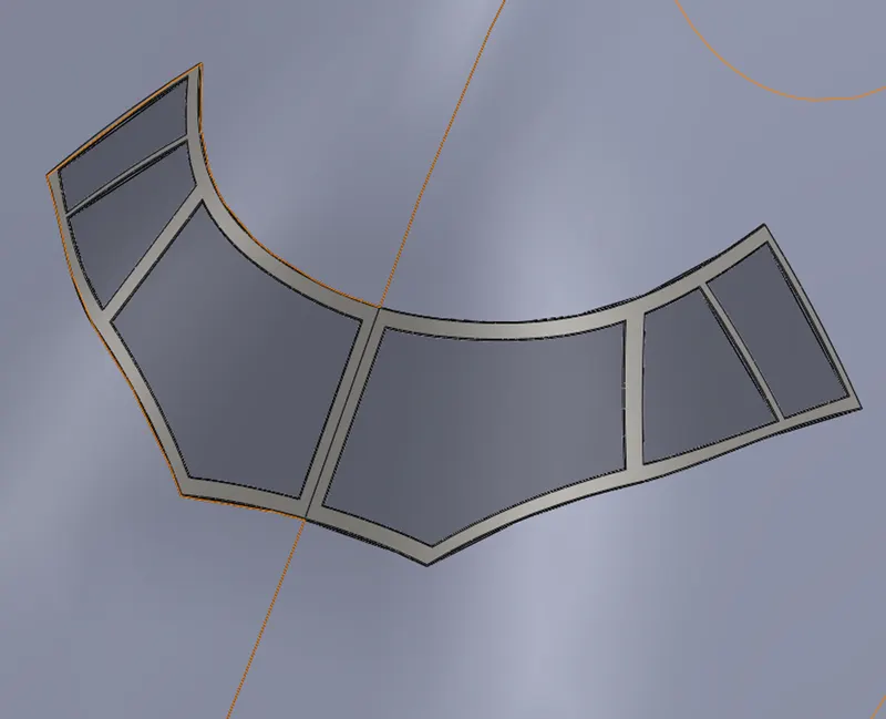
Cockpit window is created using sketches by split line command, convert entities and offset surfaces and thicken the surfaces.
Windshield wipers
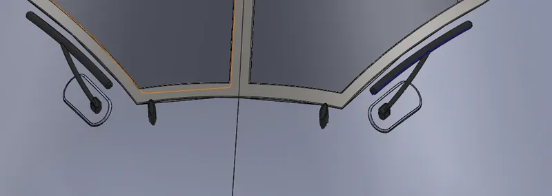
These are created using boss extrude, sweep and fillet commands on 2D sketches.
Passenger windows
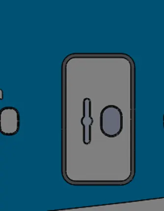
The passenger windows are created by using rectangular sketch and giving fillets and then is patterned linearly and split line command is applied selecting on faces to project and appearances are applied accordingly.

Doors and hatches
Doors and hatches are also created similar to passenger windows, sketches are drawn on a plane and are projected to faces and appearances are applied and for hatches surface offset is created and thickened and applied fillets.
Lights and antennas
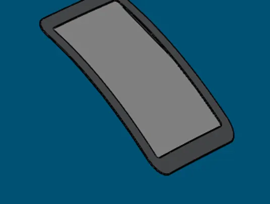
Lights and antennas are created using solid modelling features like boss extrude.
Auxiliary power unit
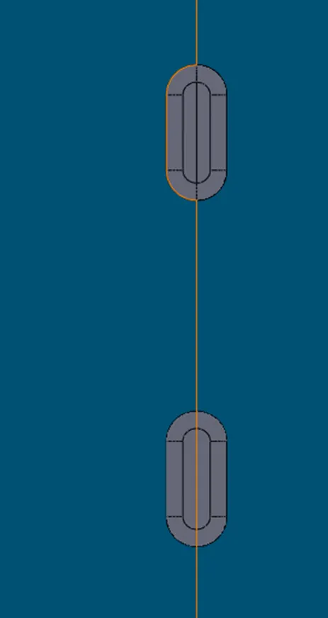
It supplies power for other than propulsion, it is made by applying solid modelling features like boss extrude, dome.
Vertical Stabilizer & Horizontal Stabilizer:
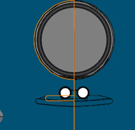
The VS keeps helps to control the aircraft from swinging side to side (yaw) and HS keeps the control from up-down motion (pitch). It is created using solid modelling features extrude boss/base, Cut extrude & Project curve.
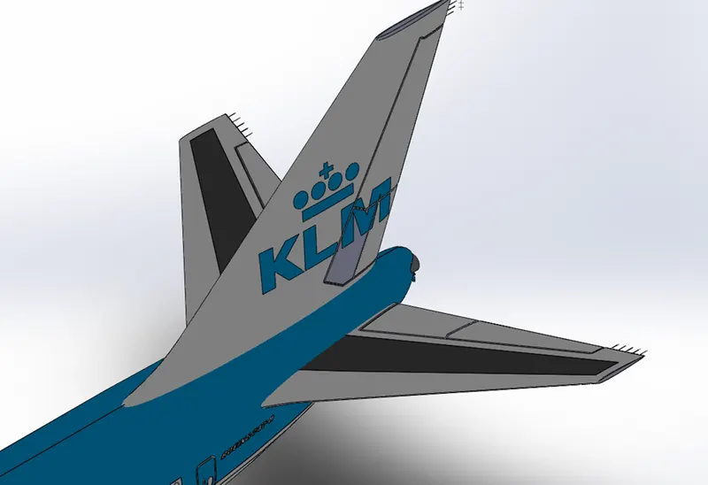
Wings flaps and ailerons are created using sloid modelling features like cut extrude thin.
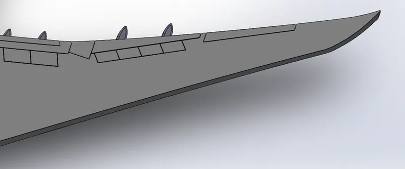
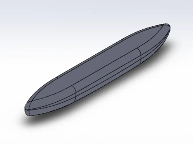
Flap track fairings are created using solid modelling techniques like boss extrude.
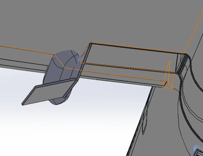
Landing Gear Axis, Hatches Closed & Hatches Opened Tools and features used are Split line, Surface offset, Thicken, Surface sweep & Mirror.
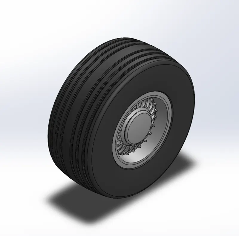
Wheels Aircraft tyres are too rigid to be forced onto a rim like automotive tyres. They are created by revolving a sketch, applying cut extrude features, applying fillets and circular patterning shell feature is applied and applying appearances finally.
Main Gear Base, Nose Gear Base, Suspension Arm & Assembly Tools
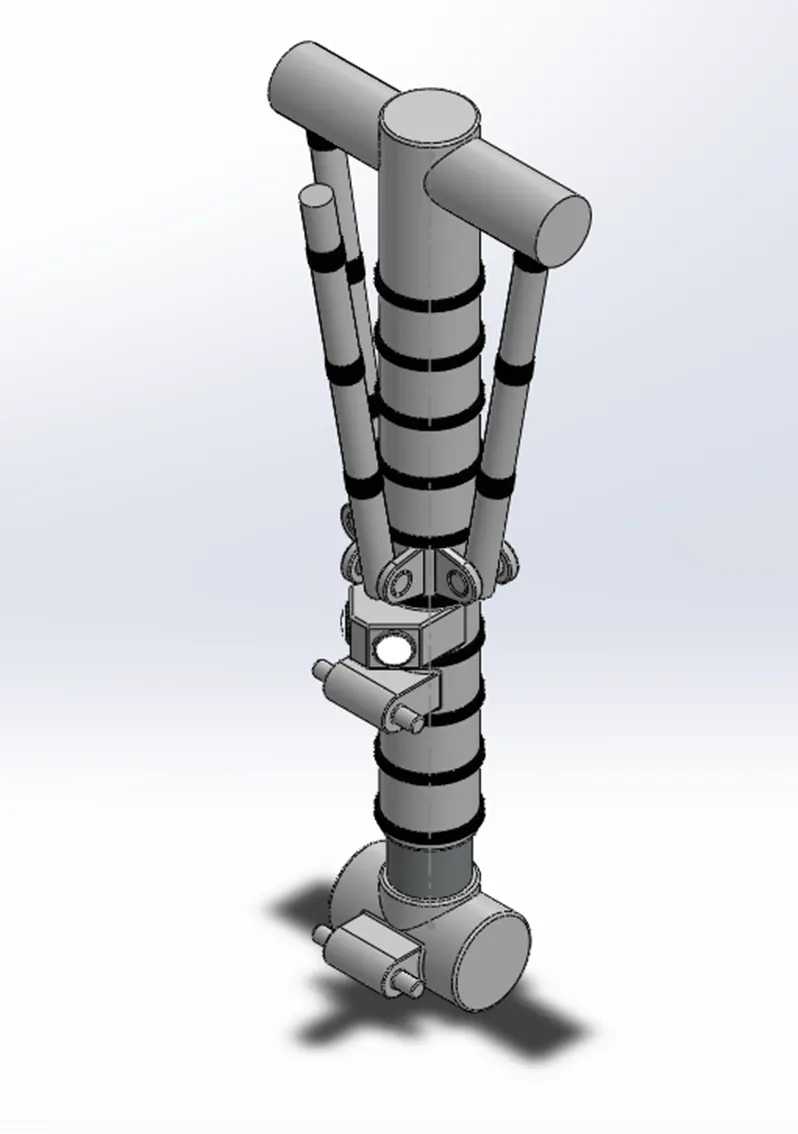
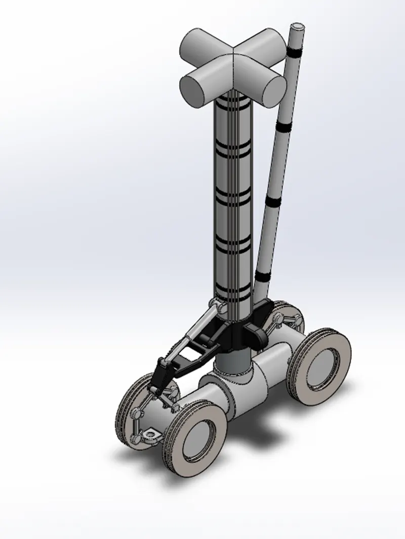
These are made by creatin a solid models using sketches from different planes and solid features are applied on it like fillets, chamfer, boss extrude, dome, cut extrude, thin extrude and also assembly is done using various mates likes coincident mates, angle mates, distance mates.
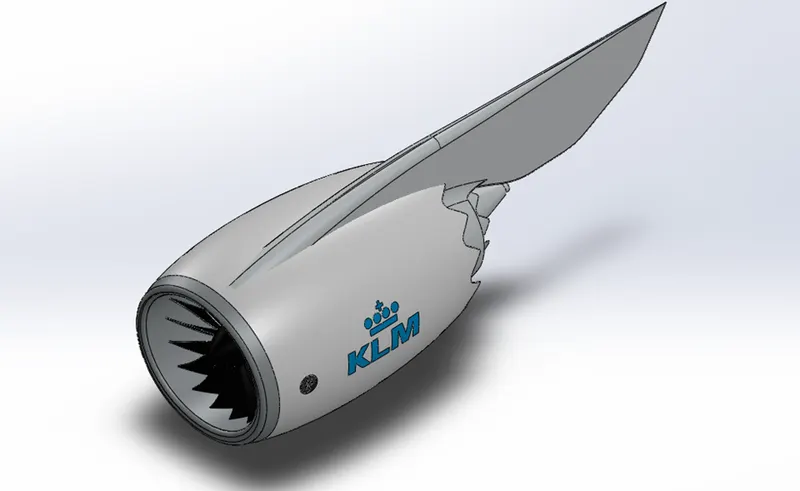
Engine
Engine is modelled separately using solid features, and blade is made using surface modelling and thickened and circular pattern is applied for blades.
Livery
Livery is applied on the left and right side of face of plane and using split line is projected on to aircraft and appearances are applied.
Assembly
Assembly is made by using various mates like mechanical mates (gear mates), advanced mates, coincident and other relation mates.
There are 2 types of assembly approaches:
Top-down approach: Here the parts are designed and assembled simultaneously.
Bottom Up approach: Here the parts designed first and then assembled with reference to a particular part.
Bottom up approach is used to assemble Aston martin, any changes made in the parts will get automatically updated in the assembly.
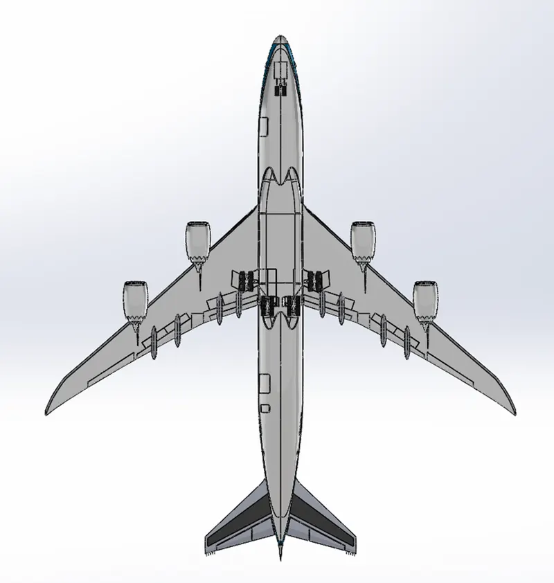
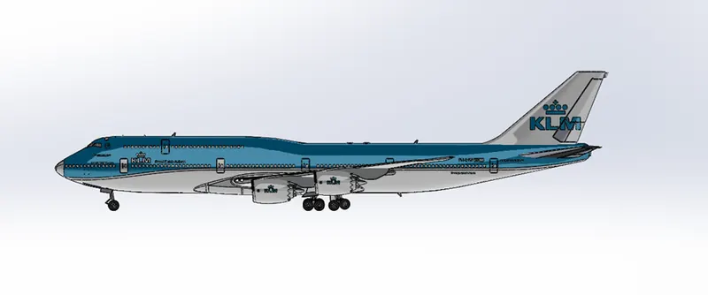
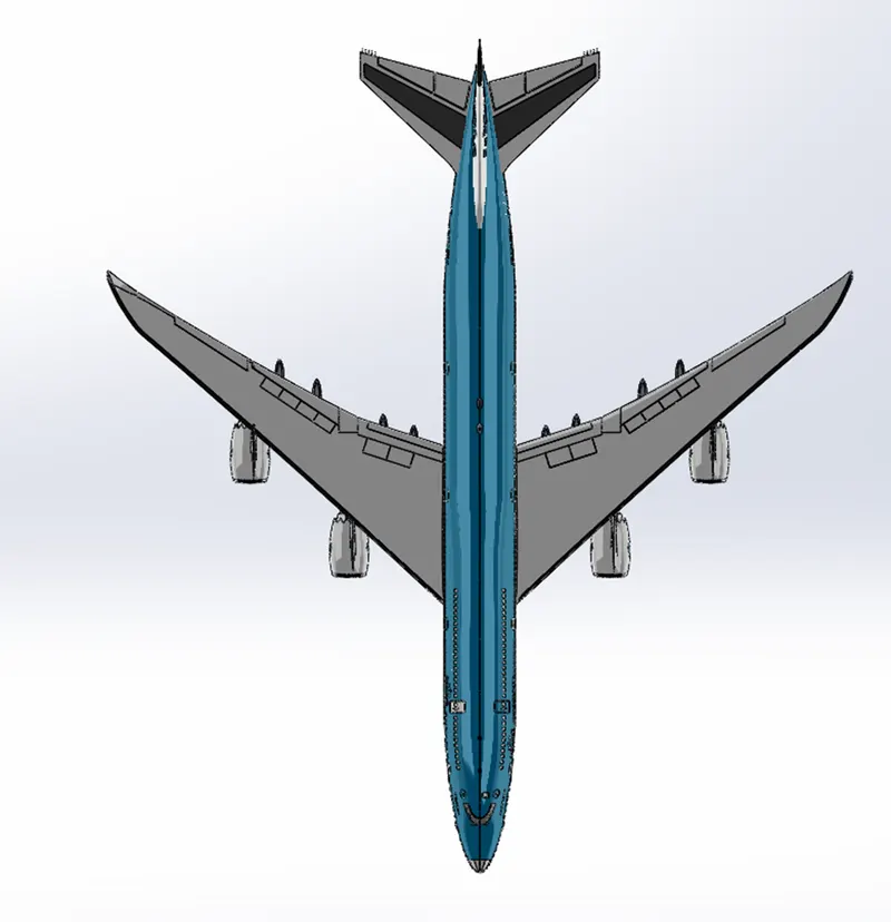
Rendering:
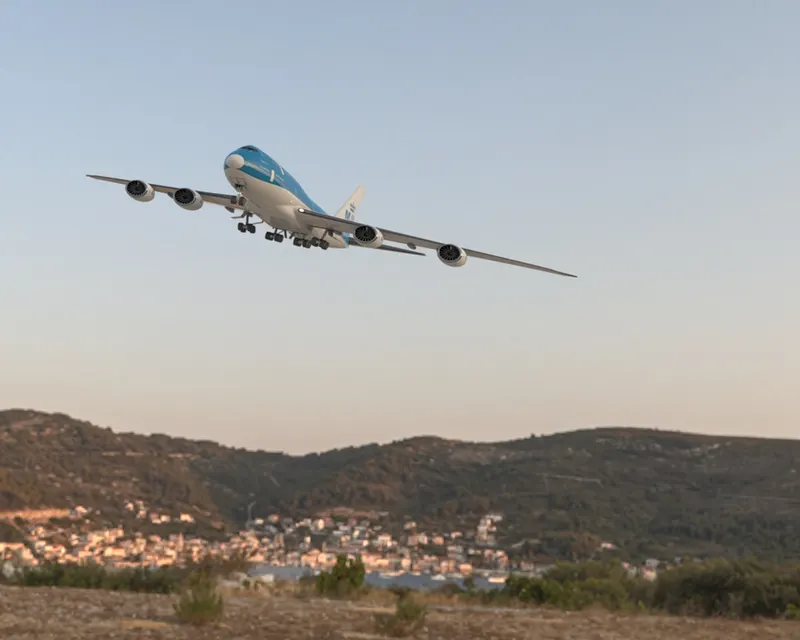
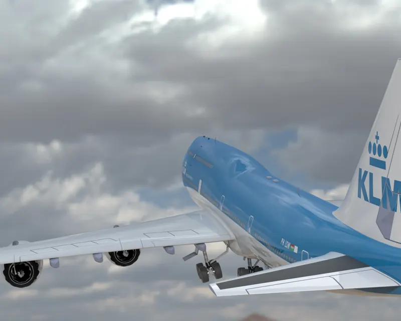
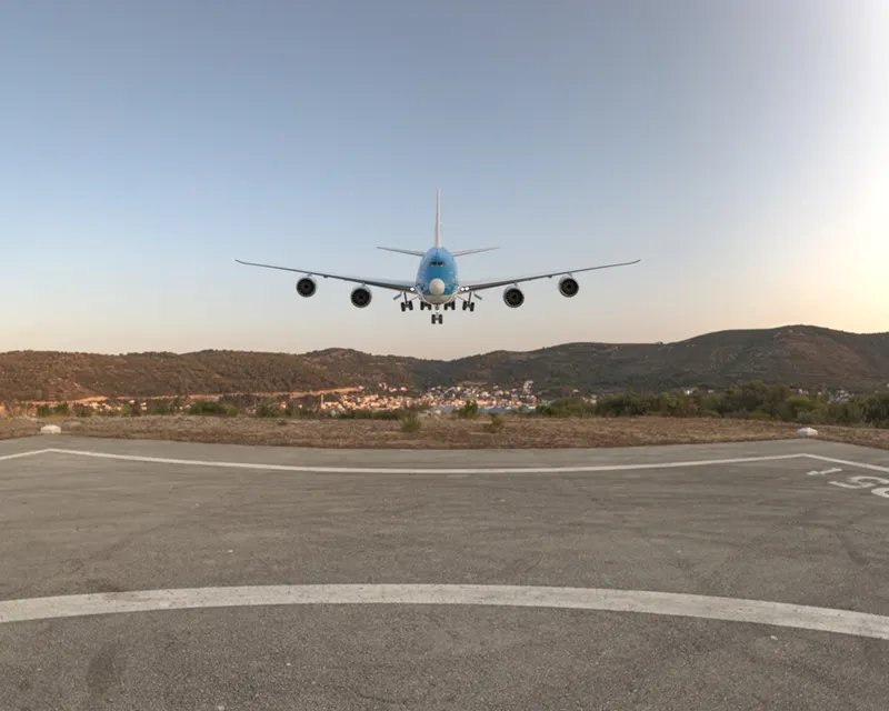
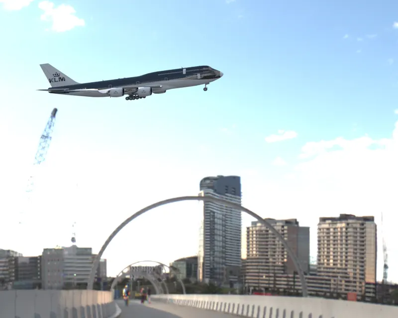
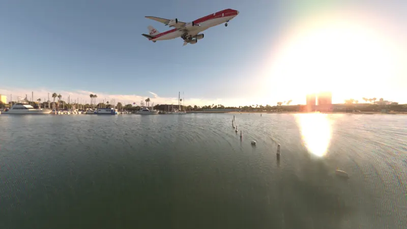
The Standard visualization rendering is done in solidworks to obtain realistic views and various views have been rendered by adjusting the lightings according to scene.
Transformation of axis and rotation of model helps us to adjust according to background.
Appearances allow us to apply paintings of colours on bodies, parts, or surfaces.
Lightings can be adjusted in the scene or assembly to match the environment and look real.
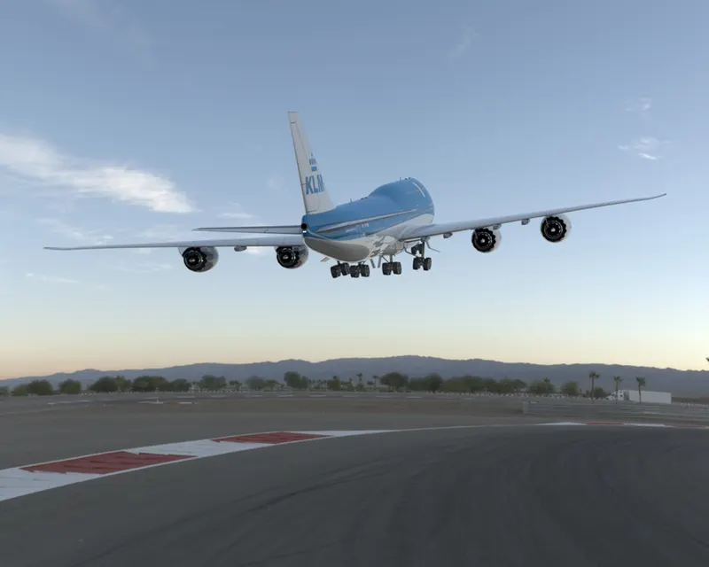 .
.
Conclusion
Boeing 747 was modelled by parts and assembled and rendered in environment to give realistic views.