Photo Realistic Rendering
Title of the Project:
- Building of a Photo realistic American Chopper Using Solidworks.
Objective of the Project:
- Understanding the tools and environment of the Solidworks by Building the American Chopper from part stage and convert that into assembly and making them photorealistic rendering models.
Introduction:
The purpose of the project is to explore all the tools in the Solidworks by building all the parts required to build the American chopper and assemble them together and make them look like a Photo realistic model by mostly using all the features in the solidworks., and also understand the basic idea that is required to build a two-wheeler in the automobile industry and understanding basics of sketching required to design an automotive product.
Design Methodology:
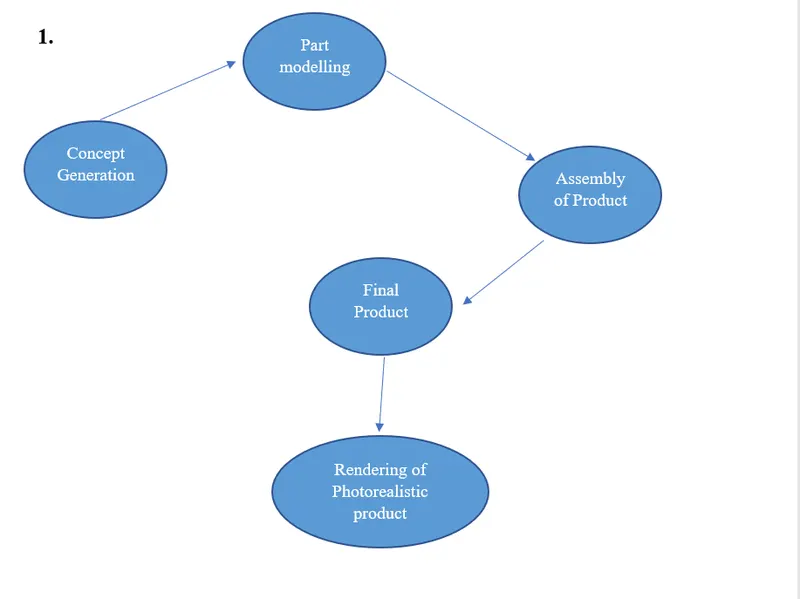
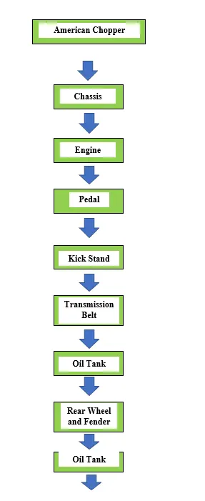
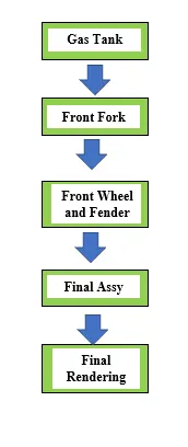
Description of the Project
Parts involved in Project:
- Transmission Belt
Commands Used: Boss Extrude, Fillet, Smart Dimension
- Draw a Sketch using the Front Plane and Constrain all the sketch.
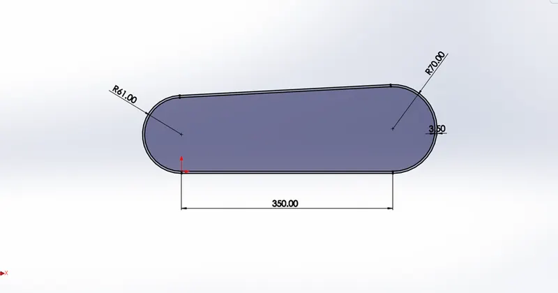
- Use Boss Extrude and Provide a dimension of 88MM with Blind Condition.
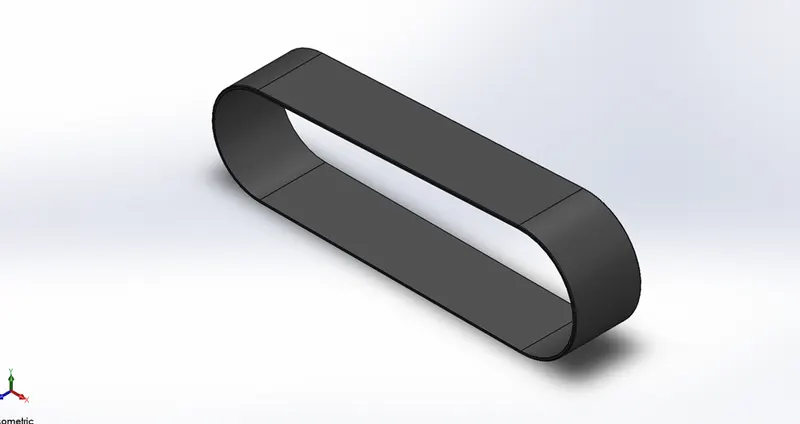
- Provide required appearance using Appearance command.
2.Kickstand
Commands Used: Loft, Dome, Cut Extrude, Fillet, Smart Dimension, Split, Spline.
- Draw a Sketch using Midplane.
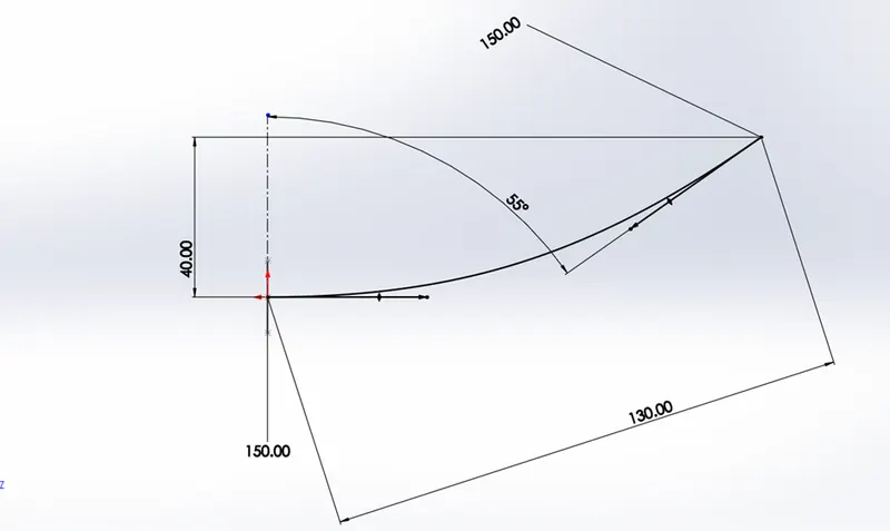
- Create a Reference Plane using Spline and its Point as shown Below.
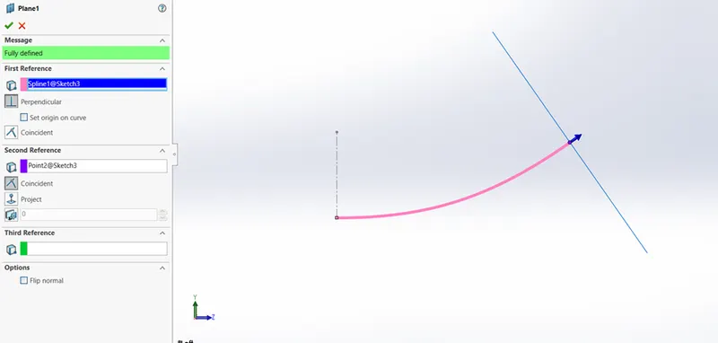
- Draw an Ellipse in the created reference Plane as shown below.

- Draw an Ellipse in the front Plane as shown below.
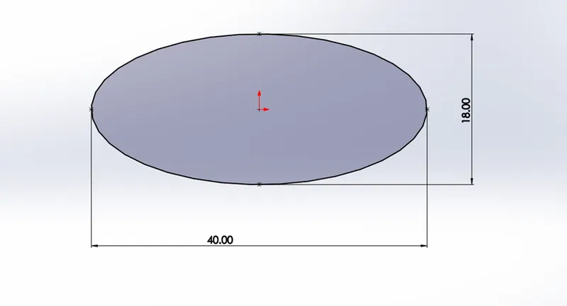
- Use Loft Geometry for created Sketch as Below.
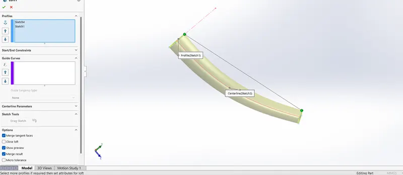
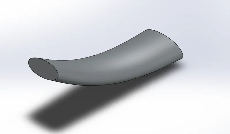
- Use Dome on both end Side to obtain the nice form.
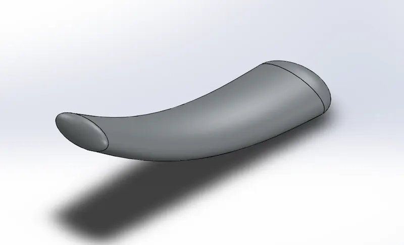
- Draw the required sketch on Midplane to get the desired cutout.
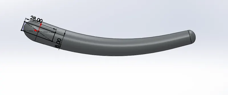
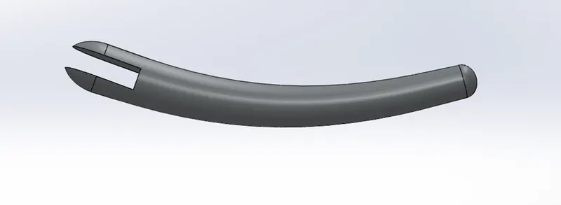
- Draw sketch on reference geometry to use split command for the cutout.
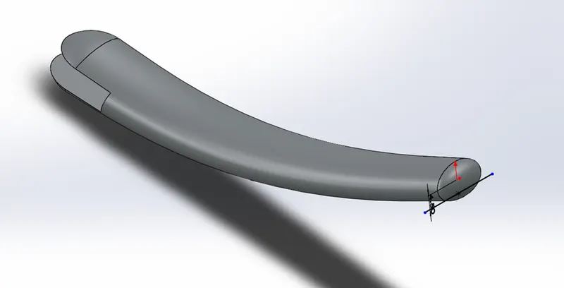
- Create a Groove using Boss Extrude as shown Below.
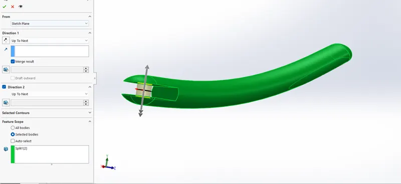
- Provide Suitable Fillets as required.
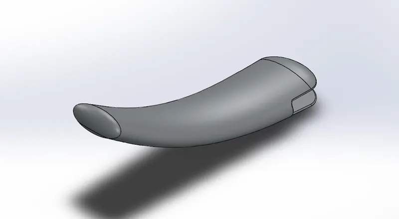
3. Front Fender and Rear Fender.
Front Fender
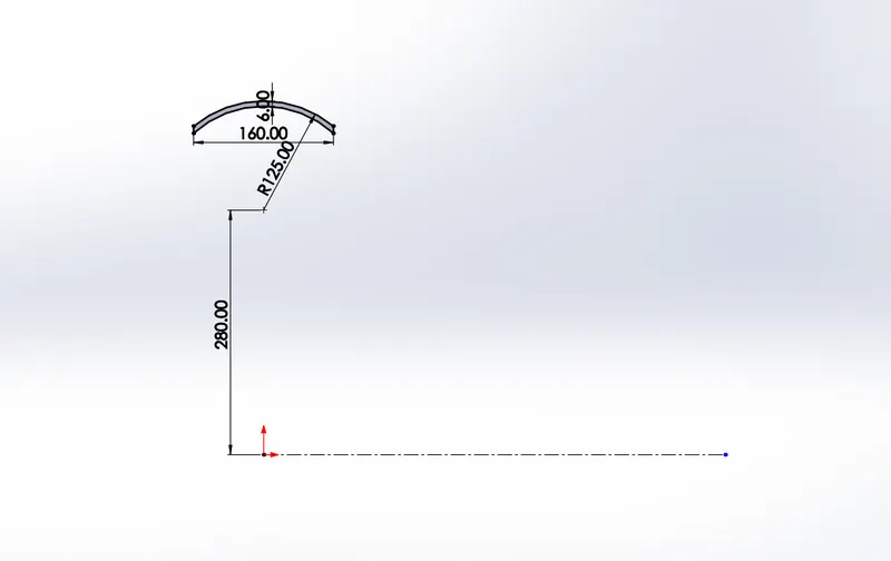
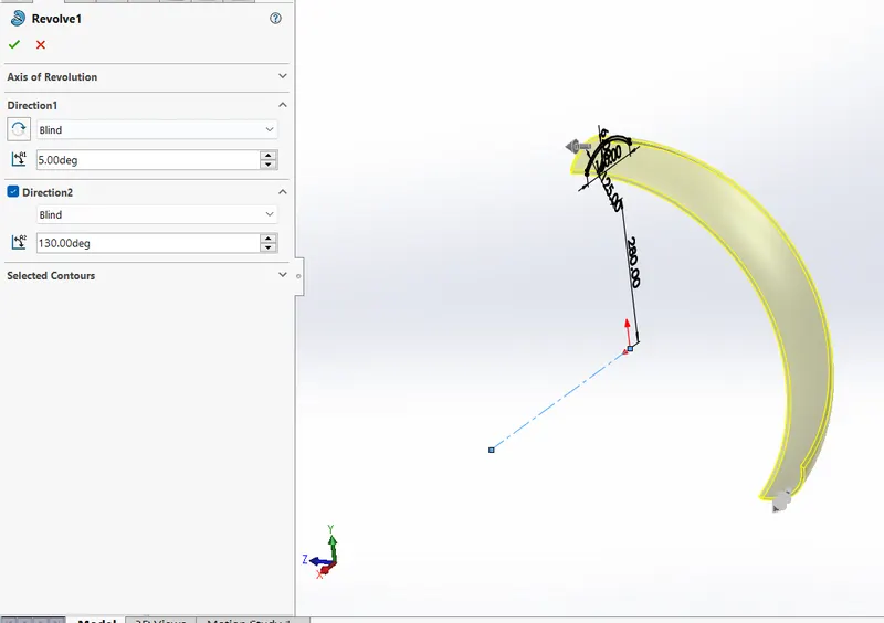
Commands Used : Sketch ,Line ,Arc, Spline , Revolved Boss ,Split , Fillet
- Draw the Sketch in the front Plane as shown below.
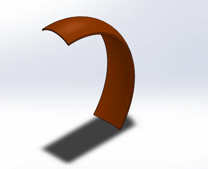
- Select Revolved Boss for the drawn sketch and provide different rotation dimension as shown below.
- Draw a Sketch on the Front Plane to remove the unwanted material using Split Option.
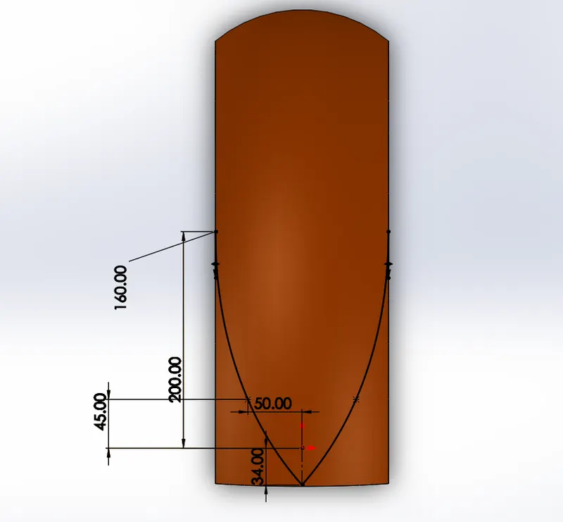
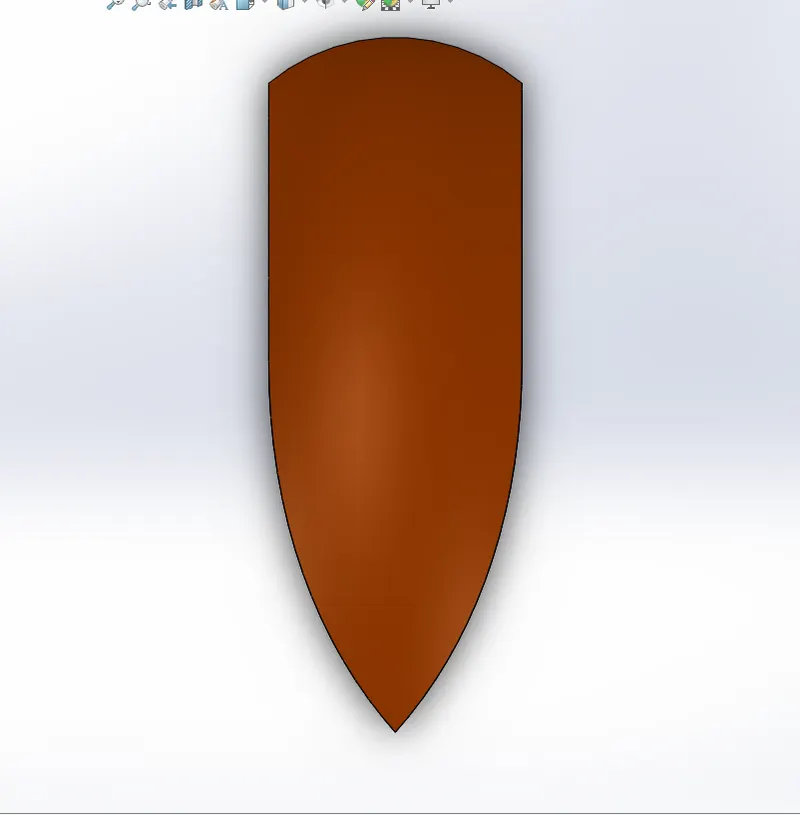
- Draw a Sketch on the Top Plane to remove the unwanted material using Split Option.
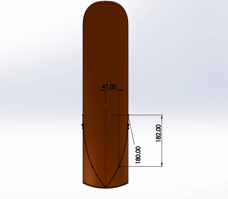
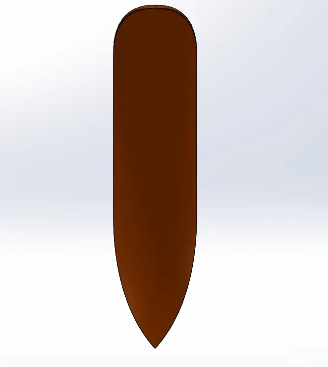
- Provide Suitable Fillets as required.
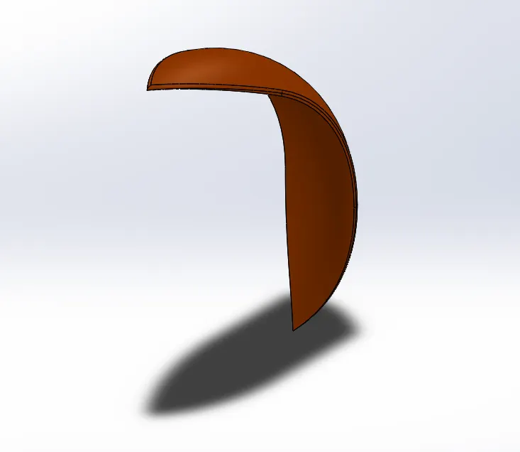
Rear Fender
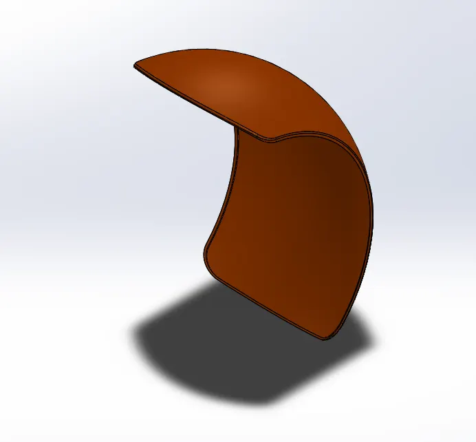
Commands Used : Sketch ,Line ,Arc, Spline , Revolved Boss ,Split , Fillet
- Draw a Sketch in the Front Plane as Shown Below.
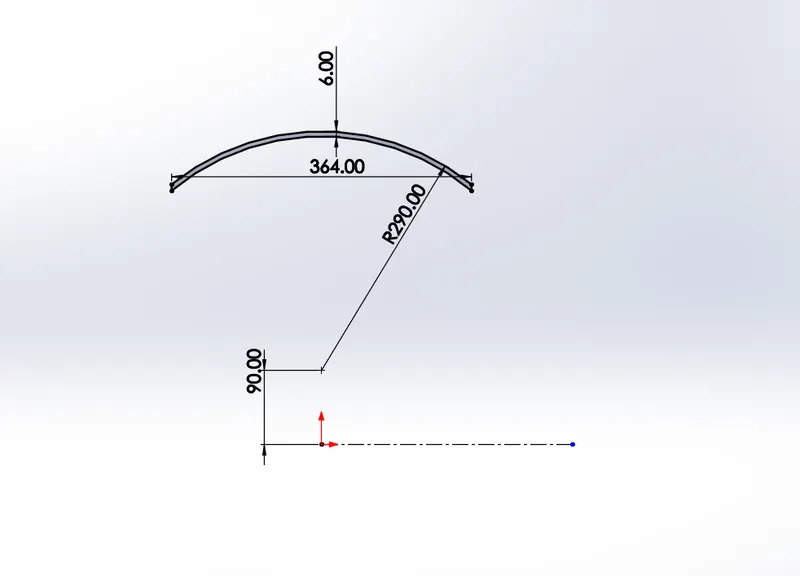
- Use Revolved Boss and give the dimension as shown below.
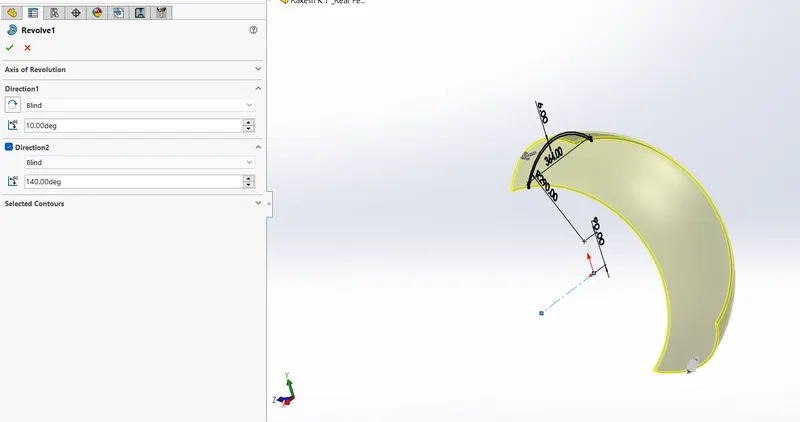
- Draw a Sketch on the Top Plane as Shown Below and use the split command to remove unwanted material.
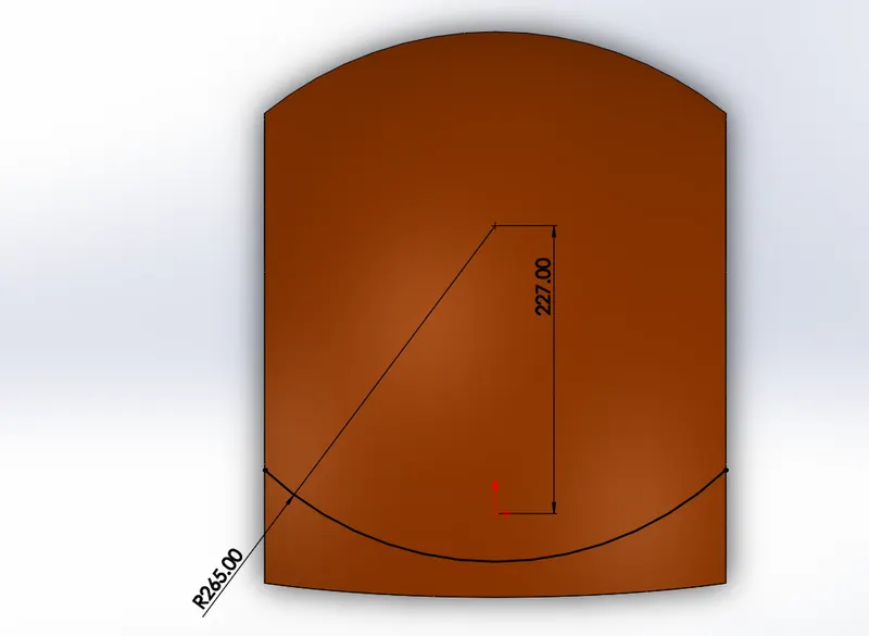
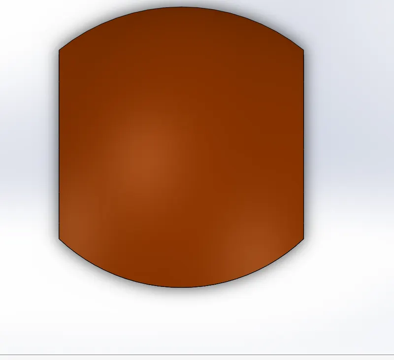
- Provide Suitable Fillets and Shell command of 4mm.
4. Chain
Commands Used : Boss Extrude , Line, 3Point Arc, Tools,Insert Sketch Block , Curve Driven Pattern ,Fillet , Mirror
- Planes are renamed as below
Front Plane - Middle Plane Chain
Top Plane - Centerplane Chain
Right Plane - Frontplane Chain
- Draw the Reference sketch on the Middle Plane Chain as shown Below
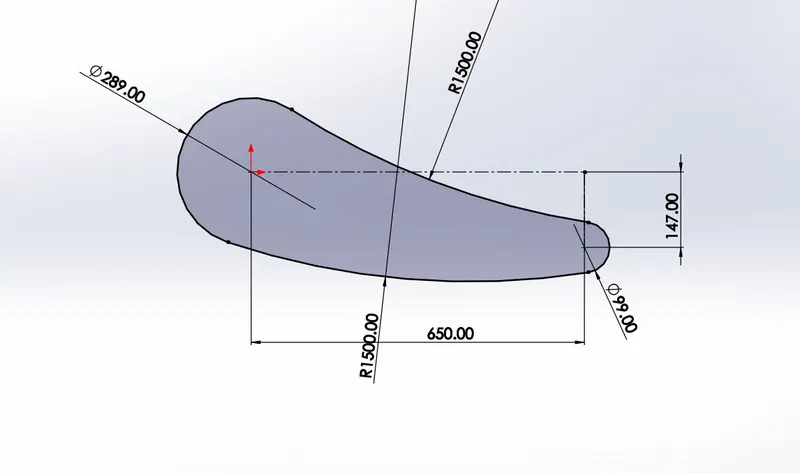
- Draw the sketch as shown below and save as them in prtdot format
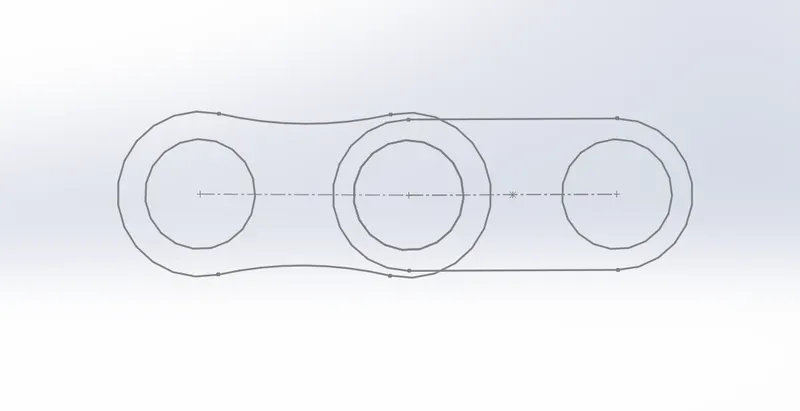
- Tools>Insert Block for the further usage of the same sketch.
- Use same above sketch and make Boss Extrude.
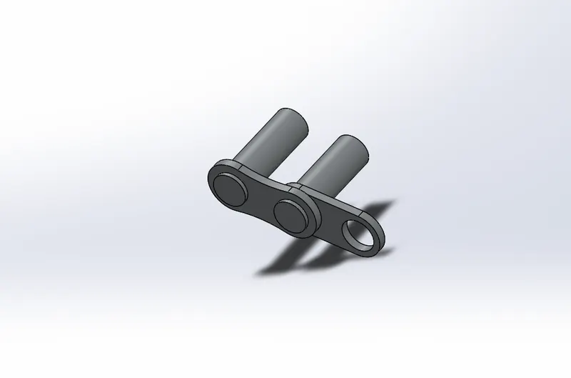
- Use curve Driven pattern for complete pattern of the above link throught the sketch.
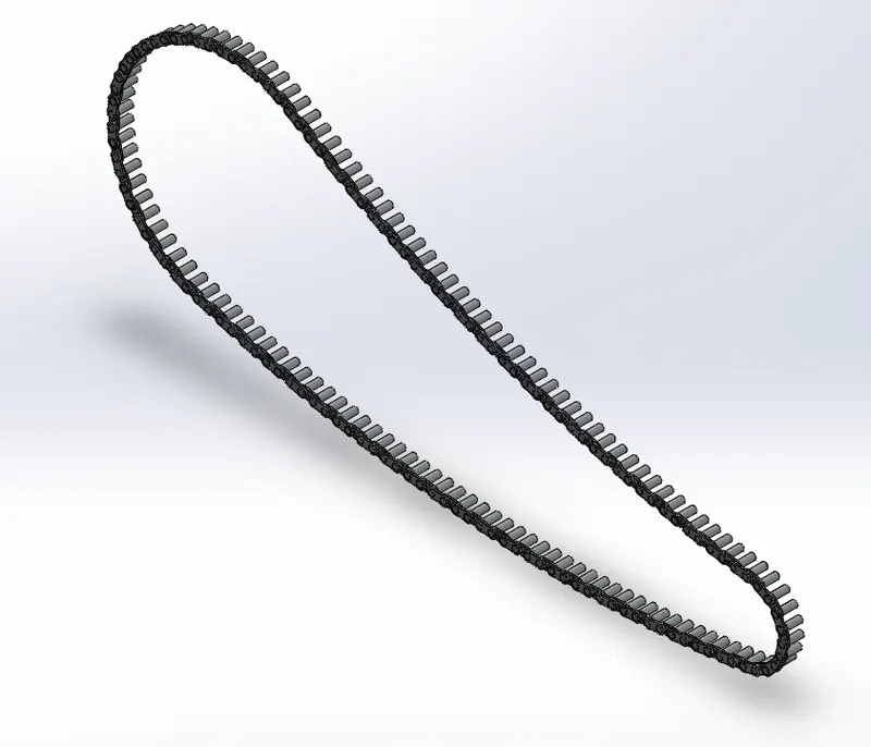
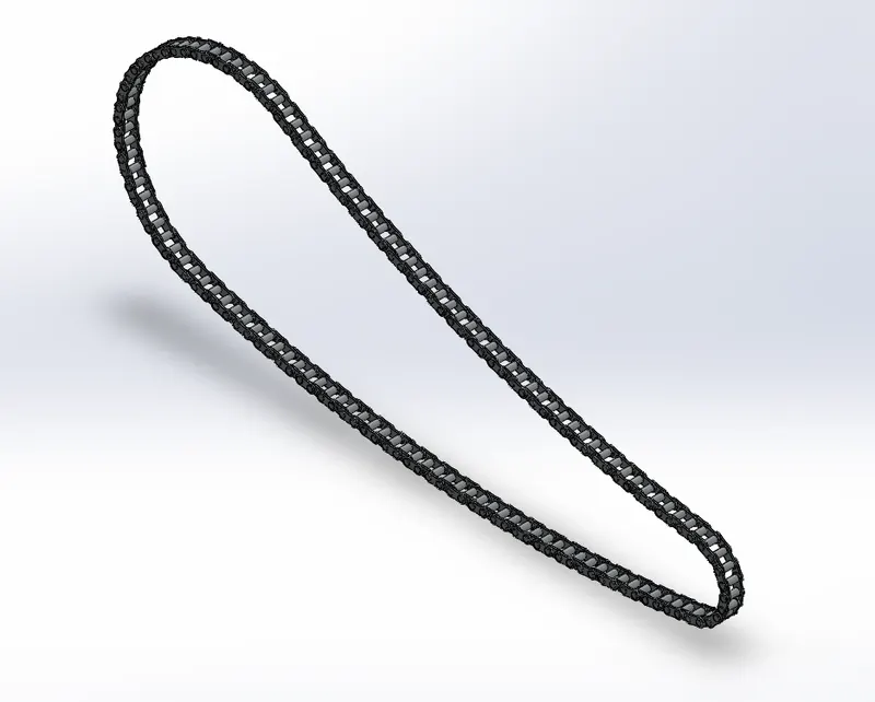
- Then Mirror the remaining Links Using Midplane Chain as reference.
5.Oil Tank
Commands Used : Boss Extrude , Combine , Fillet.
- Rename Front Plane as Midplane Oil Tank.
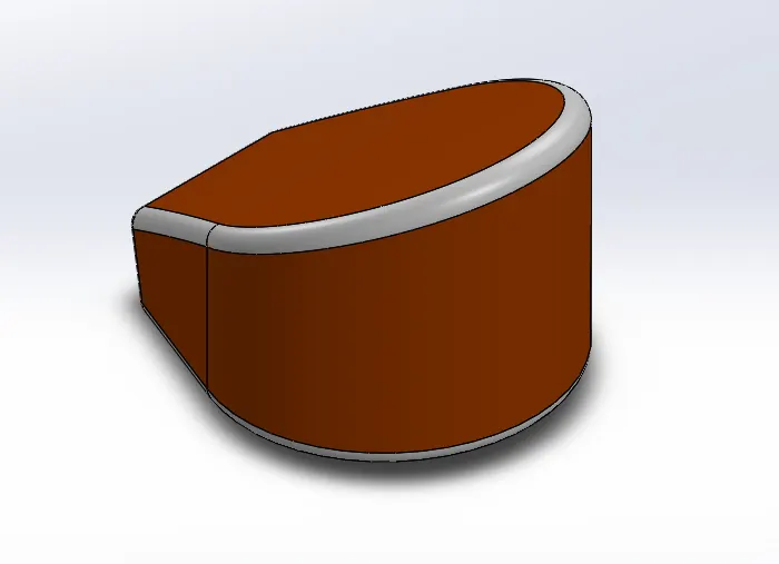
- Click on Top Plane and Sketch as per the below picture.
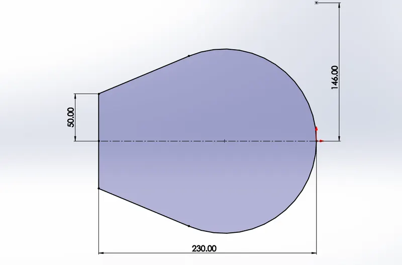
- Boss Extrude to 170mm as Shown Below.
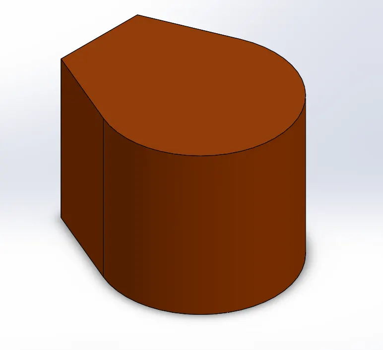
- Use MidPlane Oiltank as below.
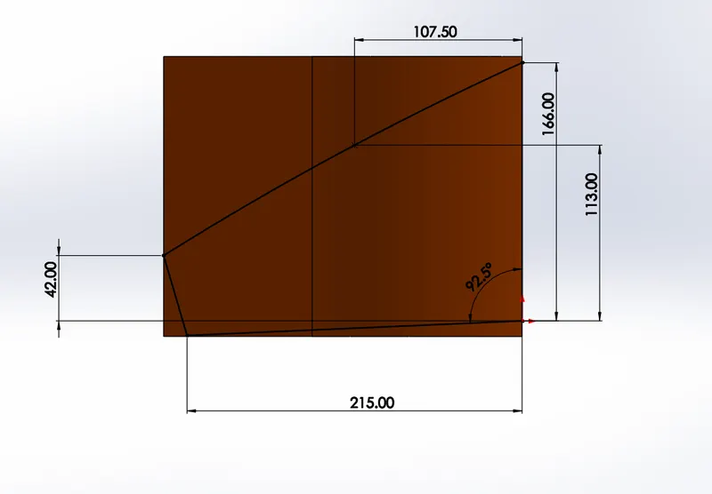
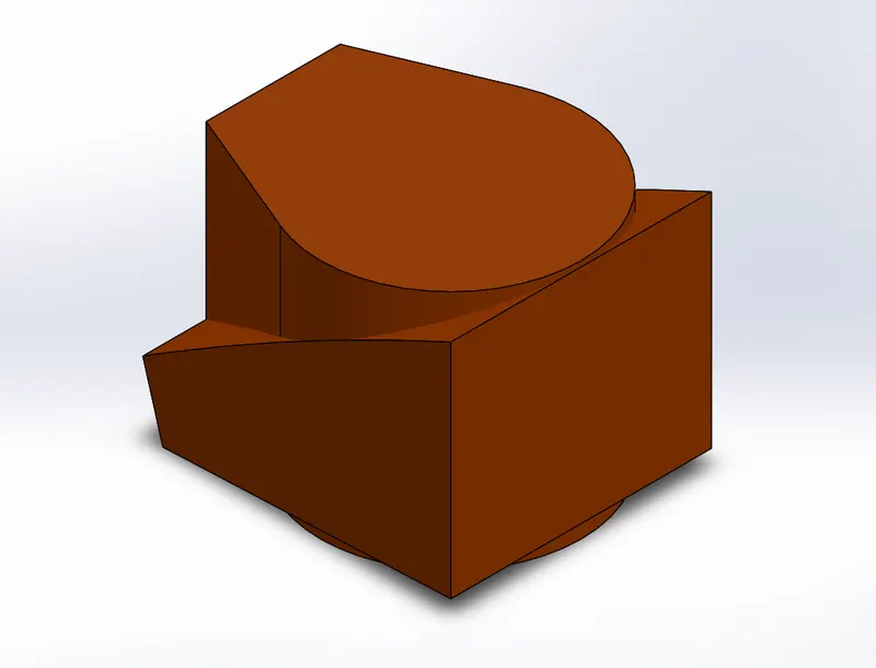
- Then use Combine option as shown Below.
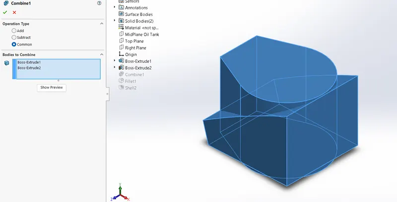
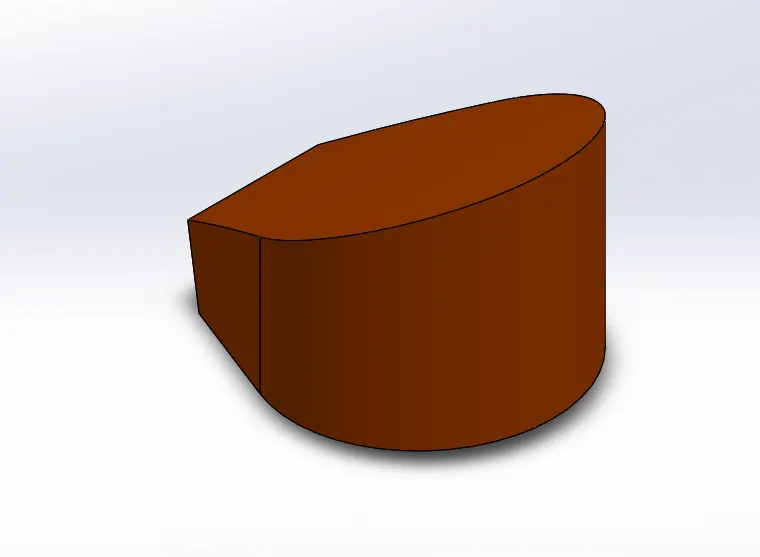
- Then use fillet and shell (3mm) as Shown below and apply suitable appearences.
6. Pedal
Commands Used : Boss Extrude , Revolved Boss, Fillet , Dome , Chamfer , Linear Pattern.
- Draw a sketch on front Plane as shown in below fig
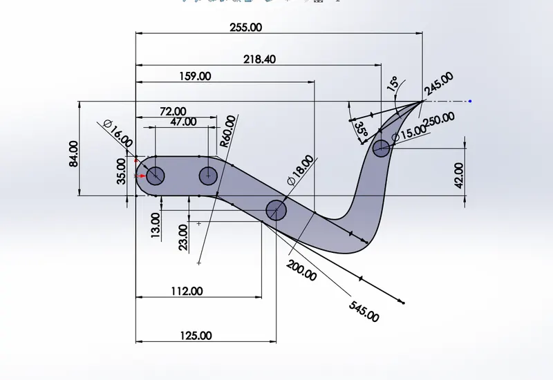
- Boss Extrude by selecting the Sketch Contour and give a dimension of 8mm.
- Boss Extrude by selecting 2 circles of dia 16mm and extrude 20mm as shown in below image.
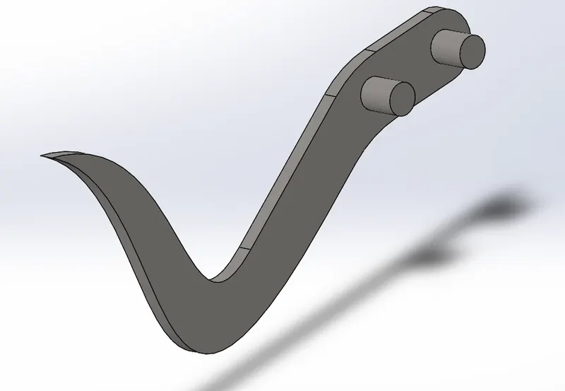
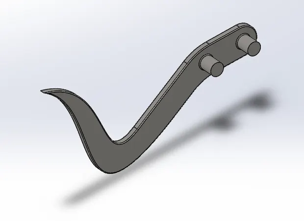
- Provide the fillet as required
- Draw a Sketch on the Top Plane as shown in below fig.
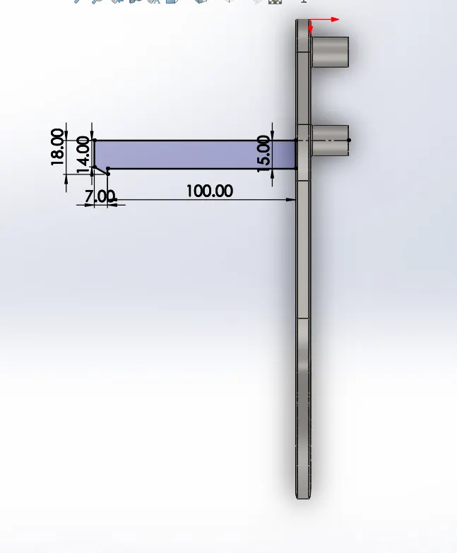
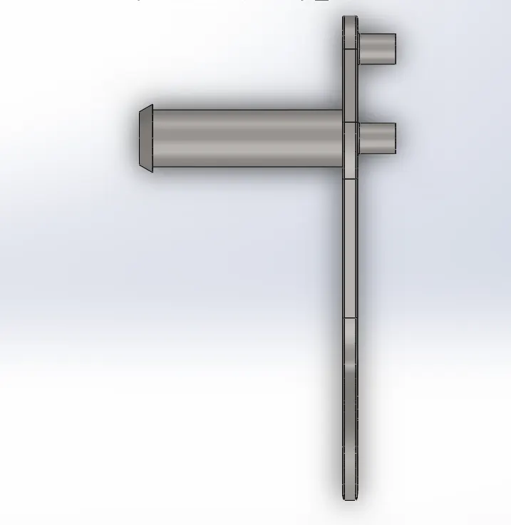
- Provide required Dome and fillet as required.
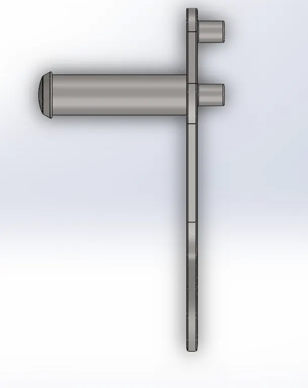
- Again select the Boss Extrude by selecting the 1st Sketch Contour Diameter of 18mm and 15 mm.
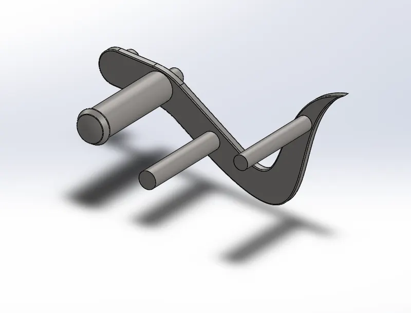
- Provide Suitable chamfer.
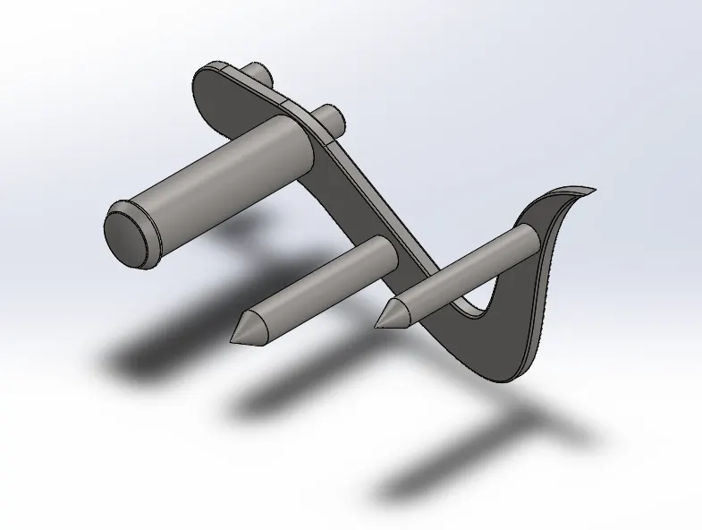
- Boss Extrude on the Front Plane by using Offset Entitles and Boss Extrude Using Offset command.
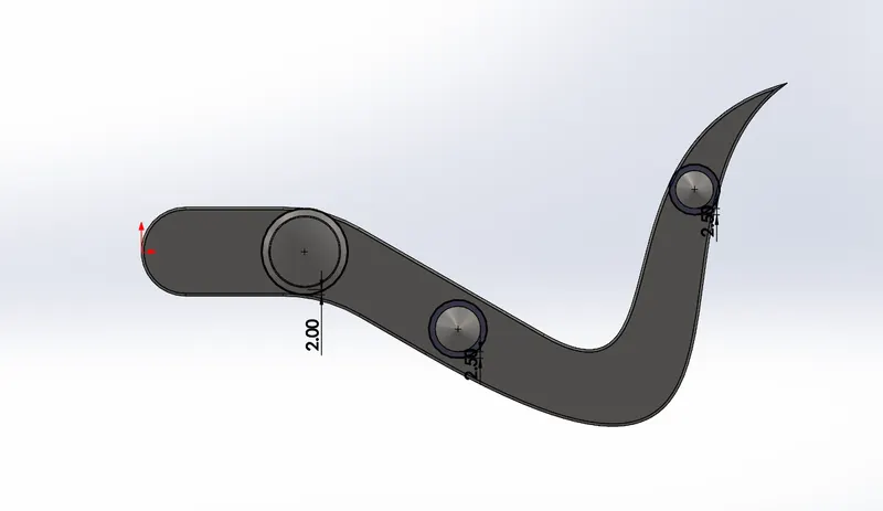
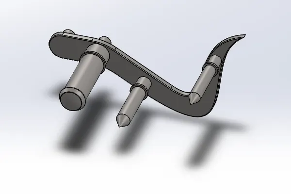
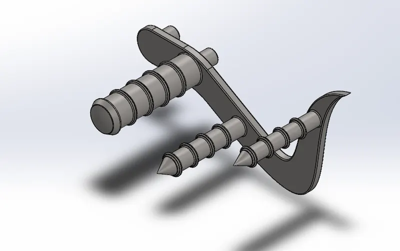
- Use Suitable fillets and Linear pattern in the pedal.
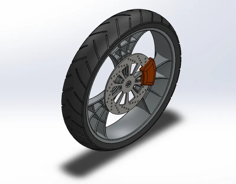
7. Front Wheel.
Commands Used : Revolve Boss , Boss Extrude ,Cut Extrude, Circular Pattern , Chamfer.
- Sketch on the Front plane as shown in below Sketch and use Revolve Boss.
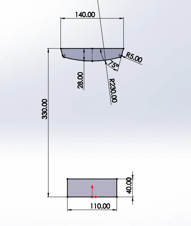
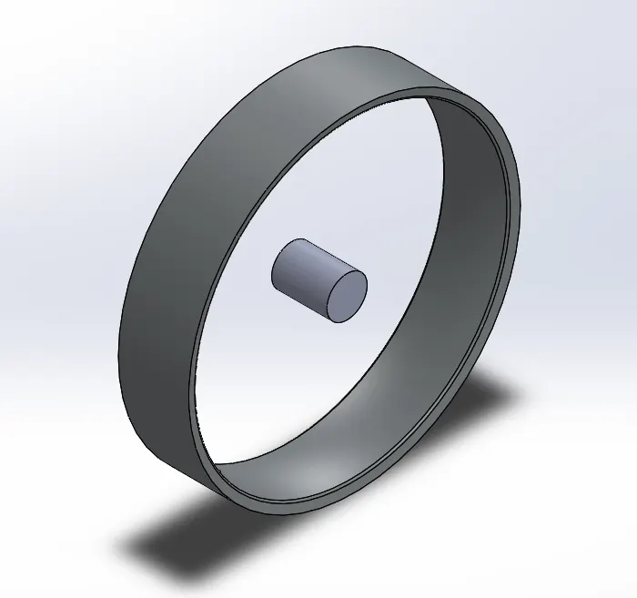
- Select Right plane and draw a Sketch for Rim as shown Below.
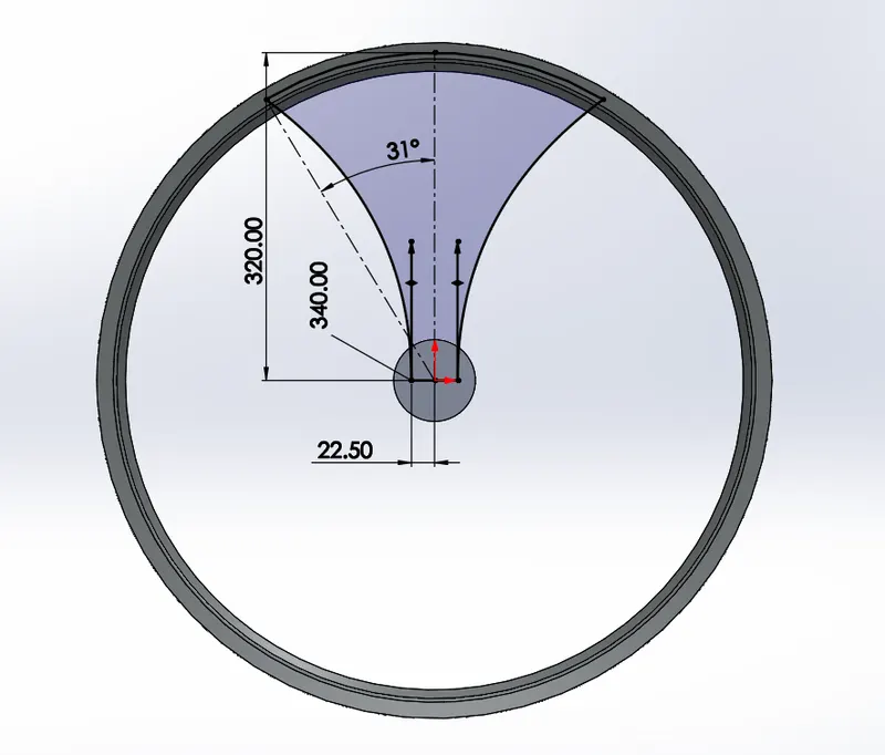
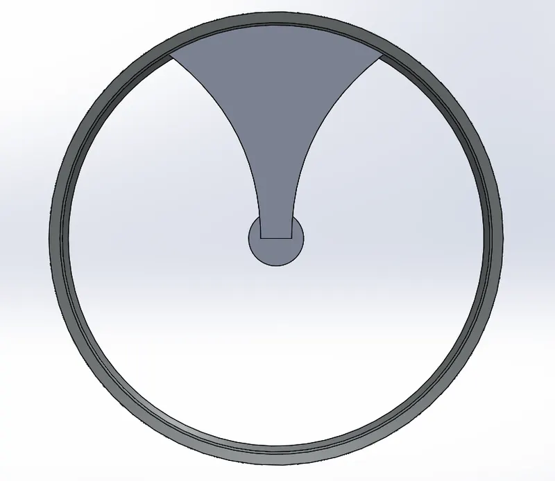
- Then Draw a Sketch on the same Plane to create cutout on the rim.
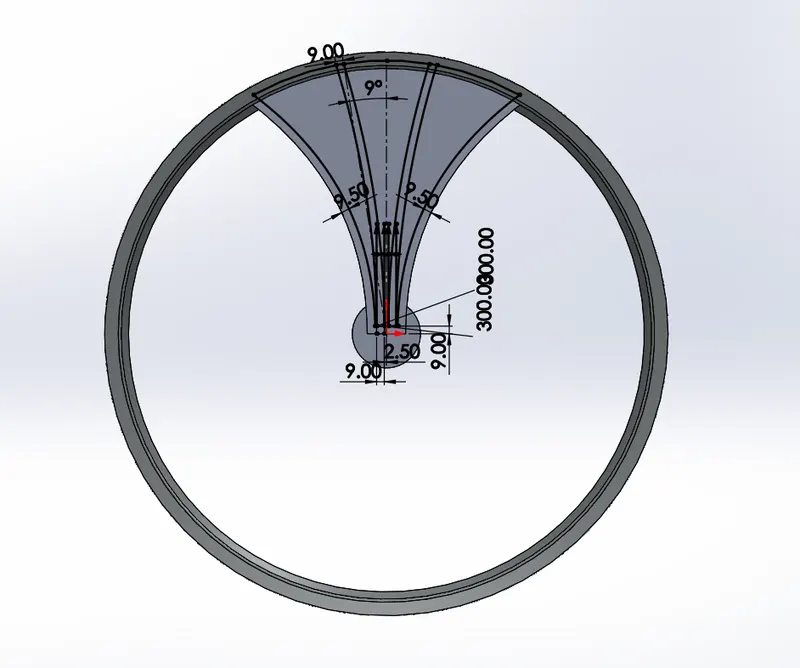
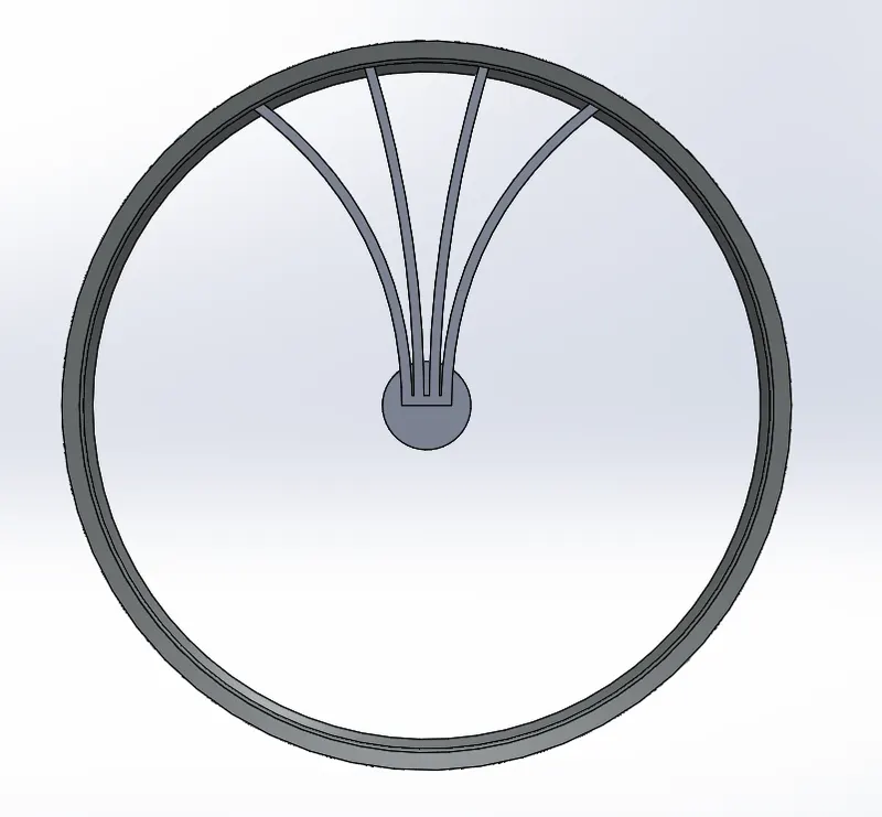
- Draw the Sketch on the same Plane of the Rim in between and Boss Extrude Them up to the surface of the rim.
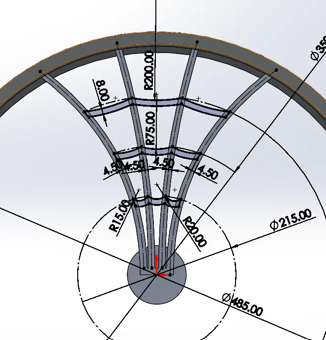
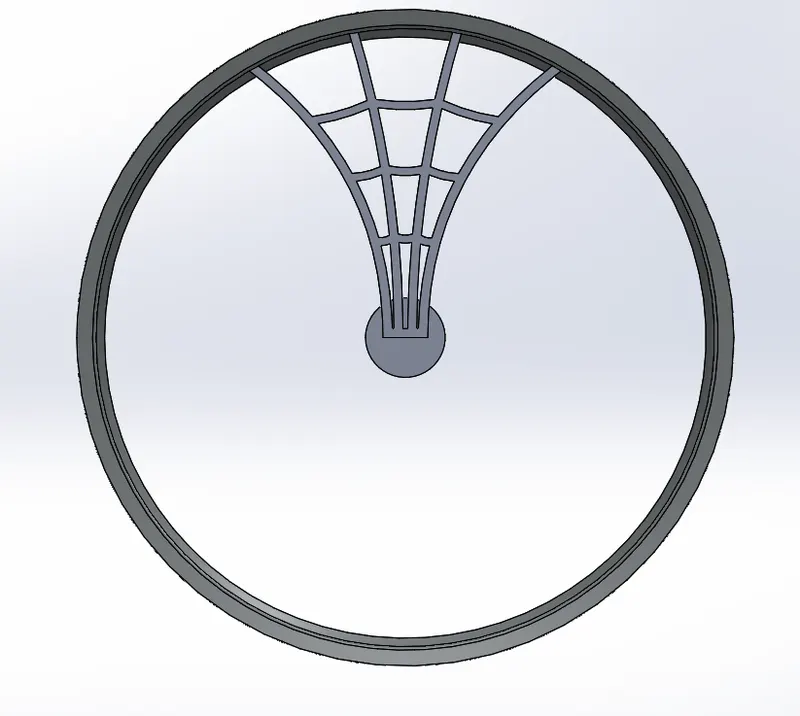
- Draw a Sketch on the Front Plane to remove the material from the rim.
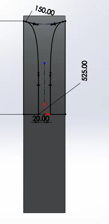
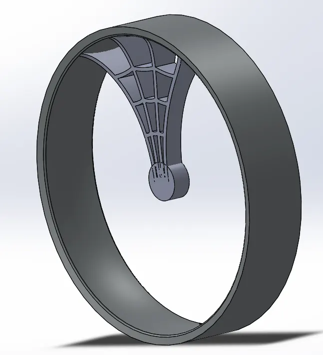
- Make Circular Pattern of the Rim 3 Instances.
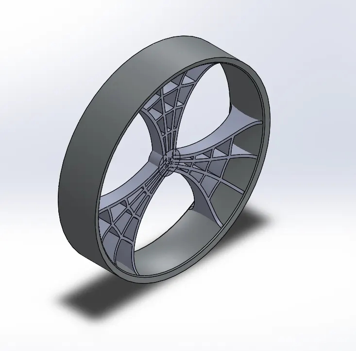
- Use the Combine Option to combine Hub and Rim.
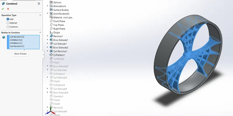
- Provide all Fillet required for the Rim.
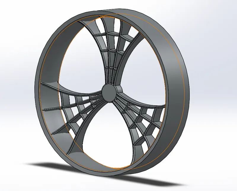
- Draw a Sketch on Right Plane to draw a rotor.
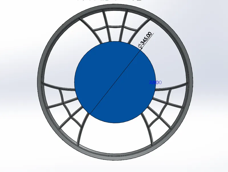
- Provide Holes on the Rotor and Circular pattern as required.
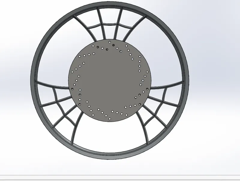
- Provide Cutout on the Right Plane using the Sketch shown below and Circular Pattern as required.
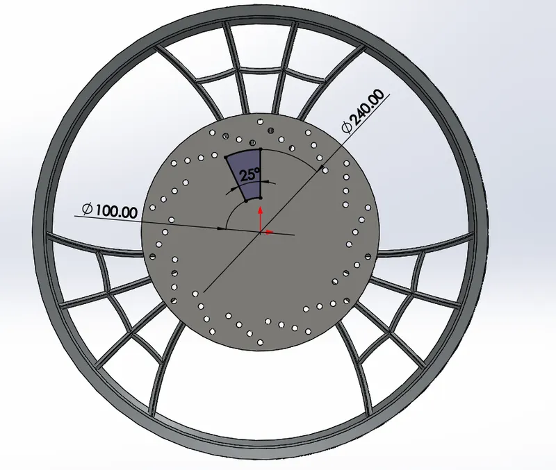
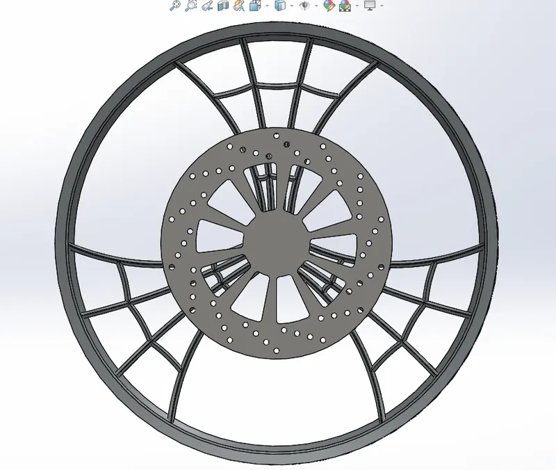
- Make a Cutout on the Hub for the Fixing as Shown in below image
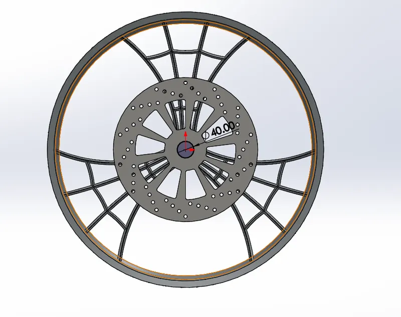
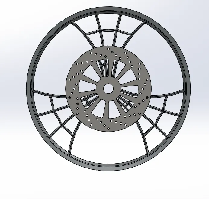
- Draw a Sketch on the Front Plane for the Caliper and provide Suitable Chamfers and Fillets.
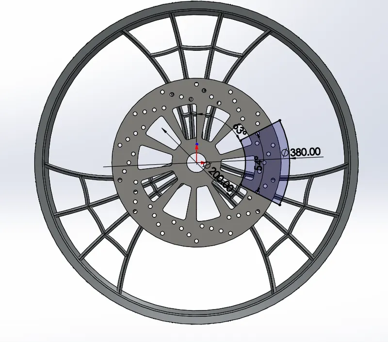
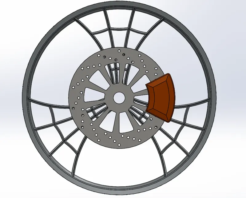
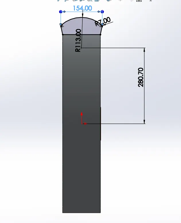
- Draw a Sketch on the Front Plane For the profile of a tyre as Shown Below and Use the Revolved Boss Command.
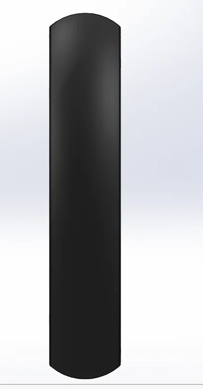
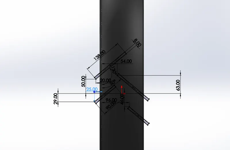
- Draw a Sketch on the Front Plane For Tyre Grip and Cut Extrude and use Circular Pattern.
8. Rear Wheel
Commands Used : Revolve Boss , Boss Extrude ,Cut Extrude, Circular Pattern , Chamfer.
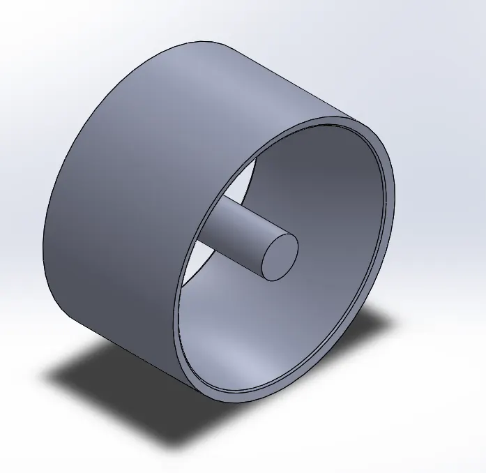
- Draw a Sketch on the front Plane and use Revolved Boss Command as Shown in below Fig.
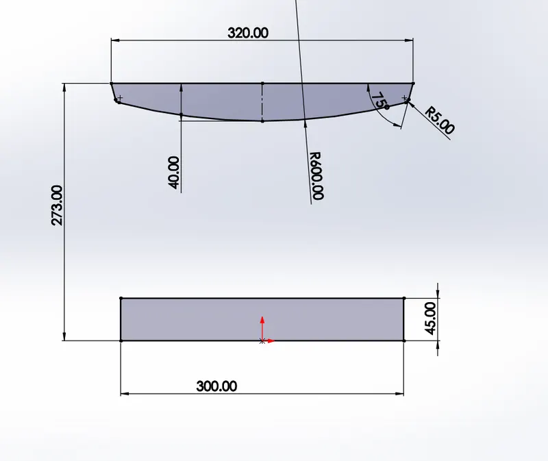
- Boss Extrude Using the below sketch on the Right Plane upto the rim as shown in below Fig.
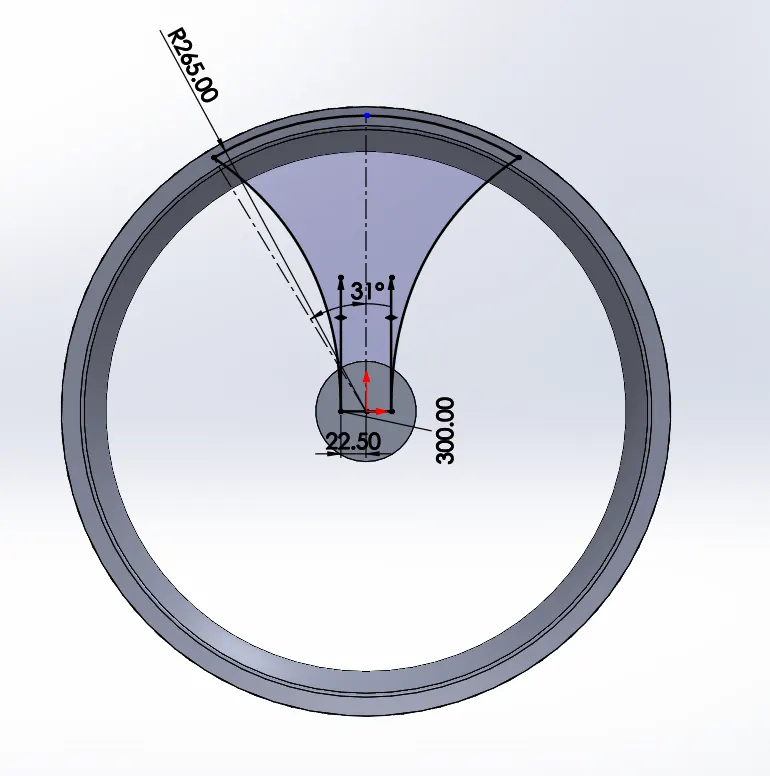
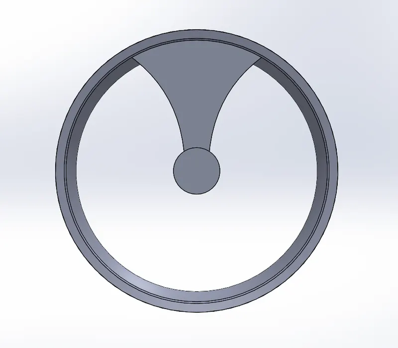
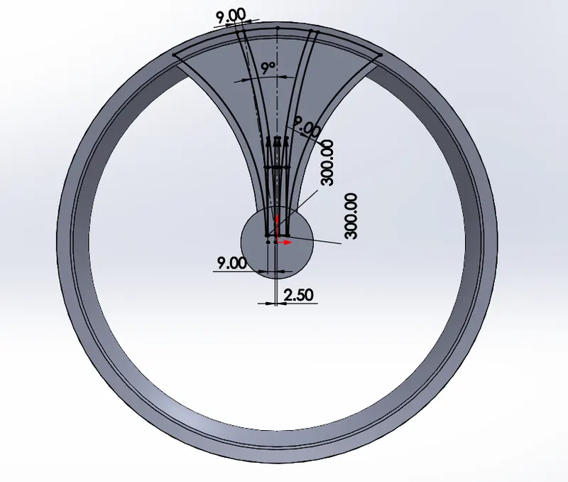
- Draw a Sketch on the Right Plane To remove Excess Material as Shown in Below Fig.
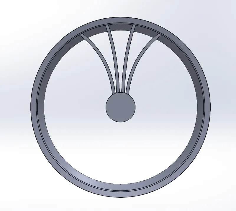
- Draw Sketch on Right plane for the Projections in the Rim as shown in below fig.
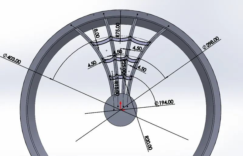
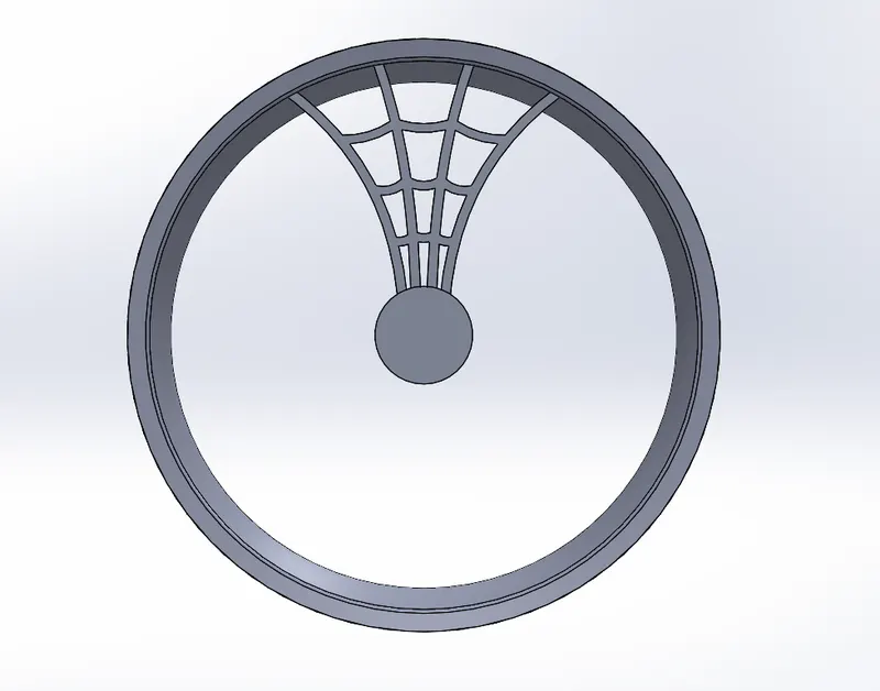
- Make Circular Pattern and Combine all the components as shown in below fig.
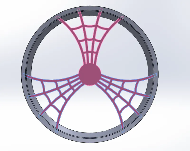
- Draw a Sketch on Front Plane and Remove Edged materials on the Rim.
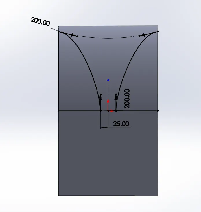
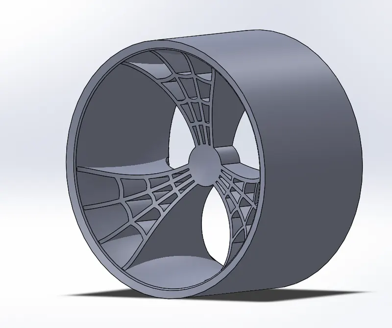
- Draw a Sketch for the Hub as shown in below fig and Use the command Cut Extrude.
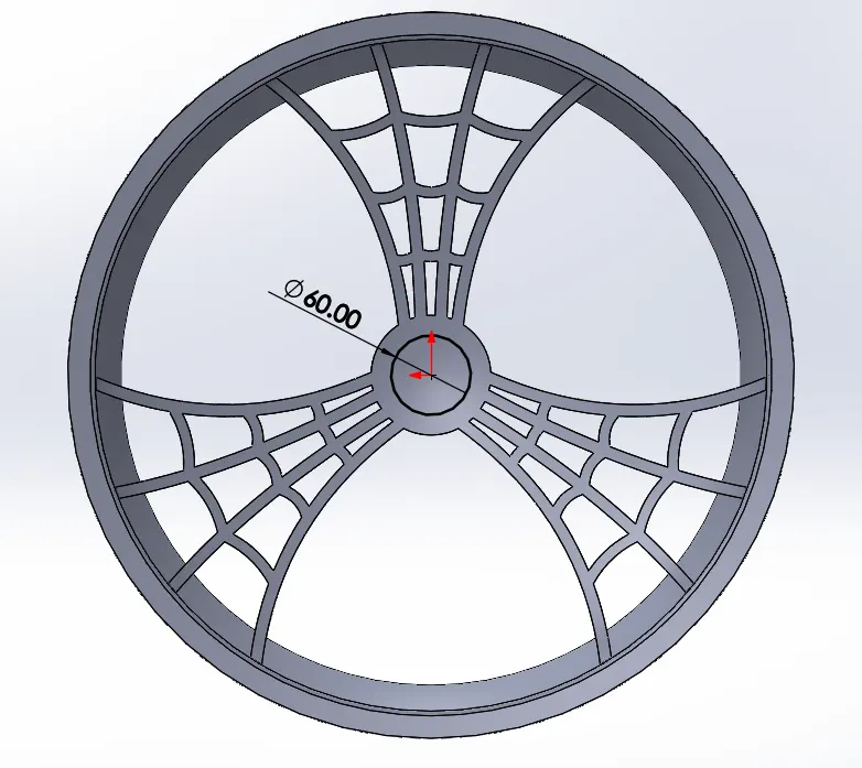
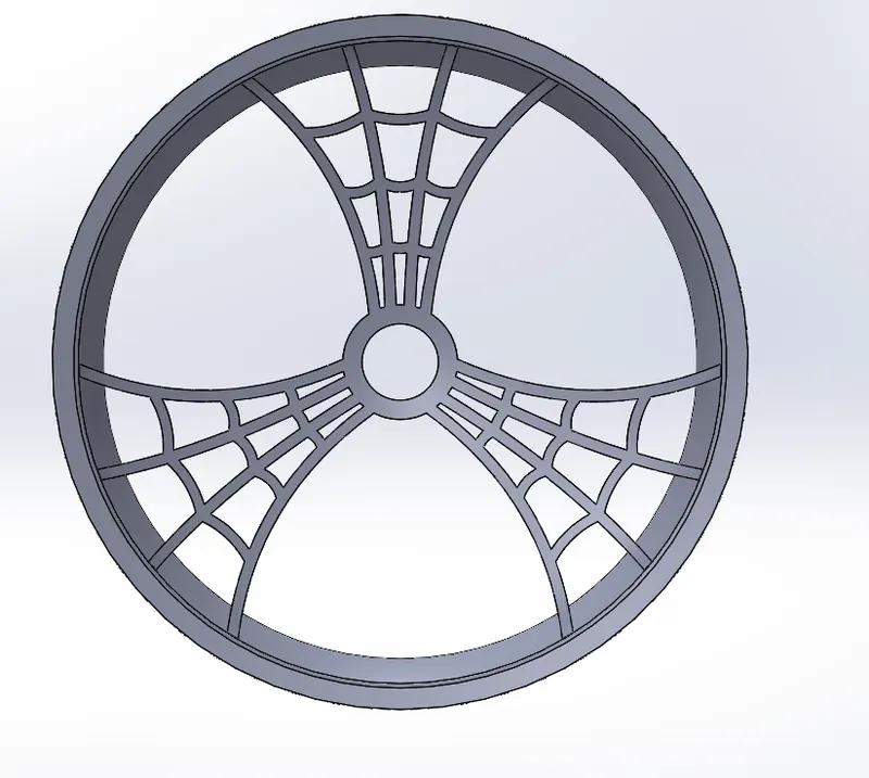
- Draw a Sketch on the Right Plane as shown in Below Fig and Use Revolved Boss Command.
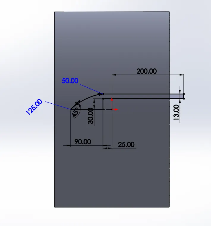
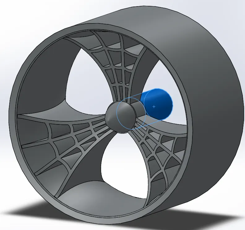
- Draw a Sketch on Right Plane for the Rotor and Use Extrude Boss Command.
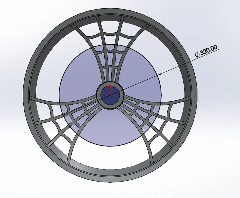
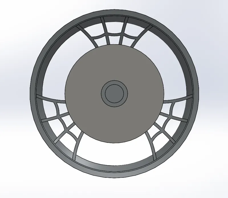
- Draw a Sketch on the front Plane and Use extrude cut and make circular Pattern as required.
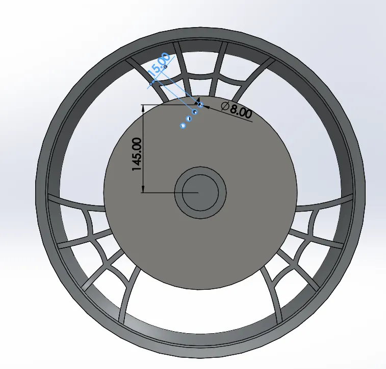
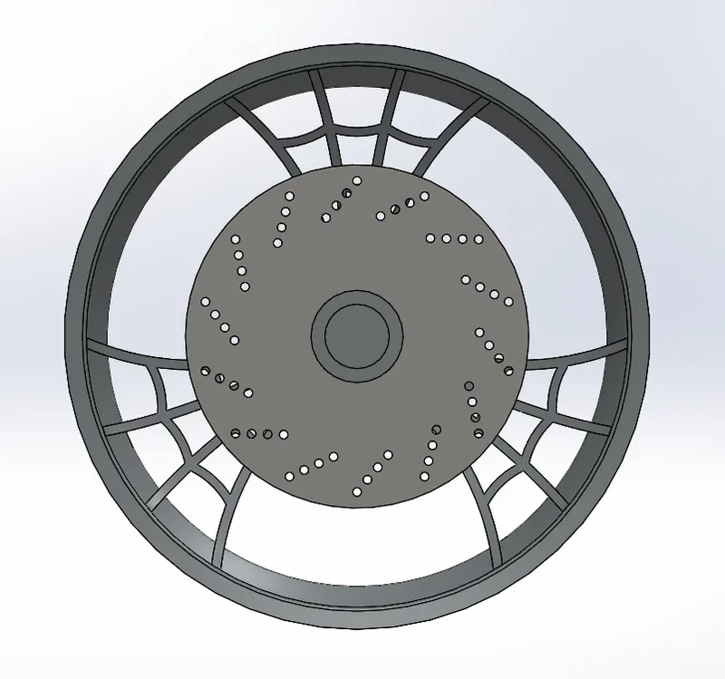
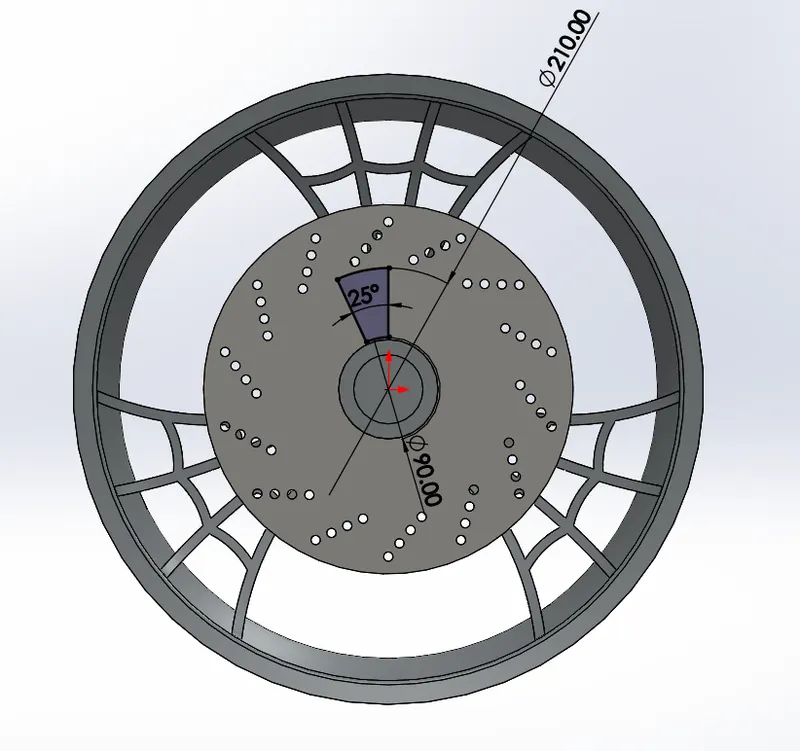
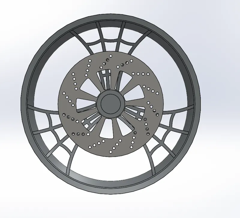
- Draw a Sketch on the Front Plane and make the cutout on the Front Plane and make circular pattern.
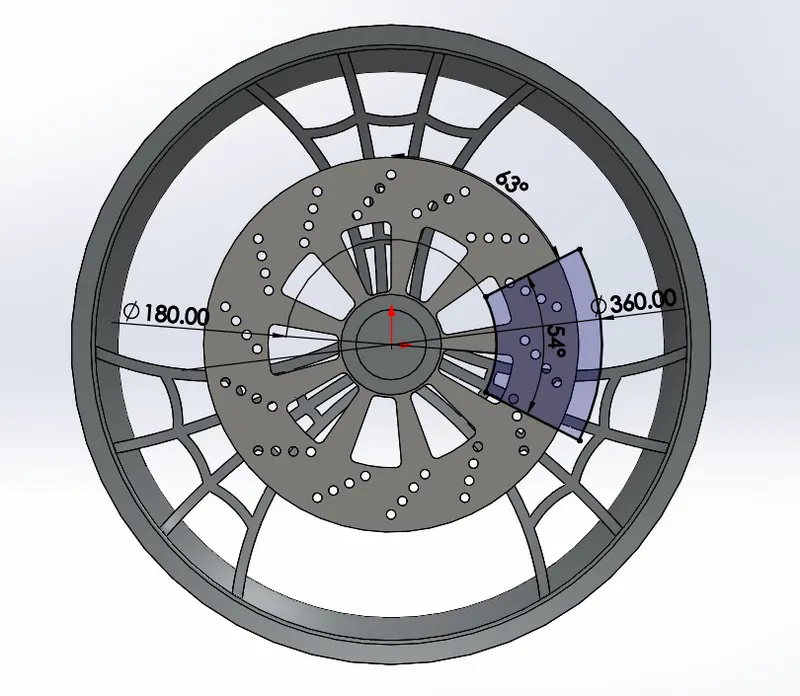
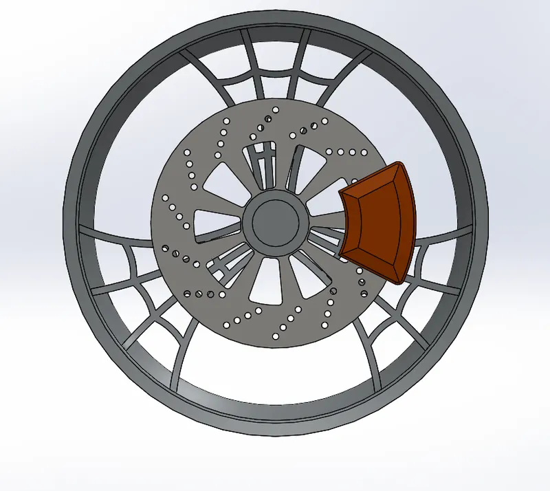
- Draw a Sketch on the Front Plane for caliper and use suitable chamfer and fillets.
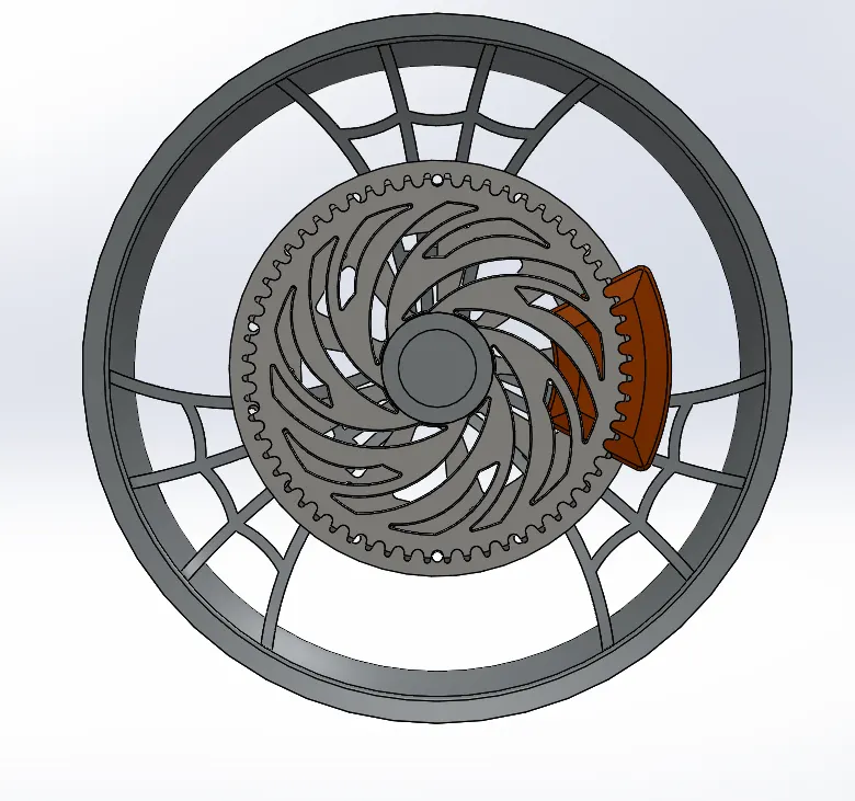
- Draw a Sketch on front Plane for the sprocket and provide suitable chamfer.
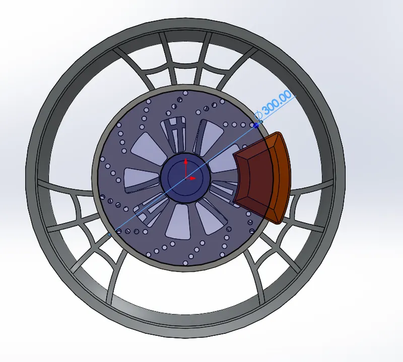
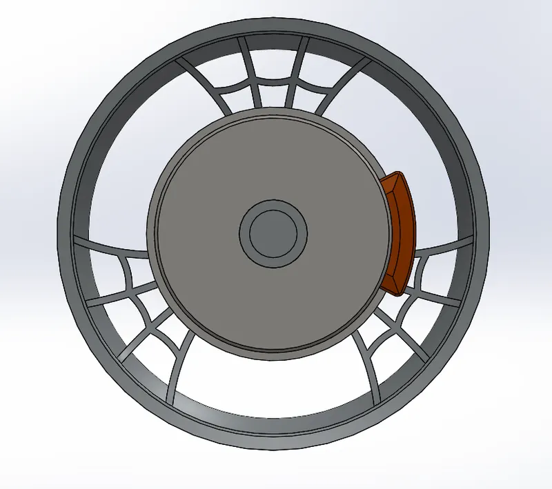
- Draw a Sketch on the front Plane for the sprocket Cutout and provide the circular pattern as required.
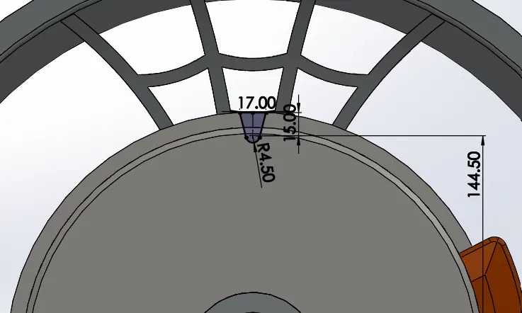
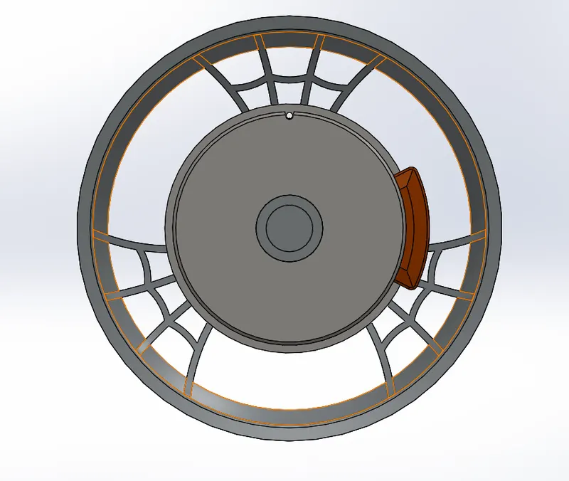
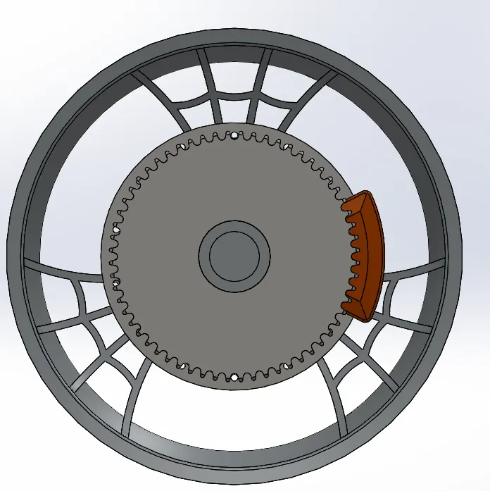
- Draw a Sketch on the Sprocket as Shown below and use command Extruded cut and provide suitable fillet.
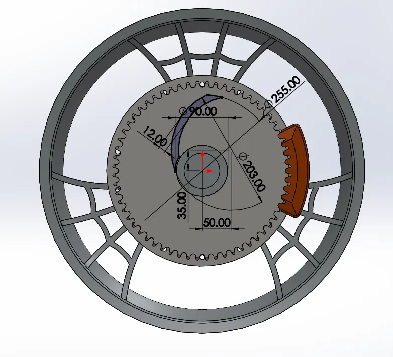

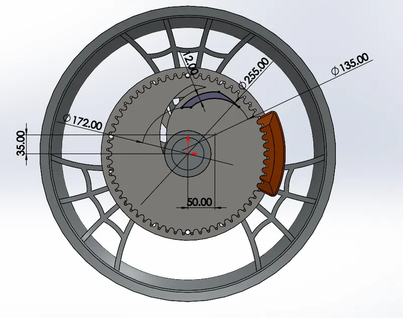
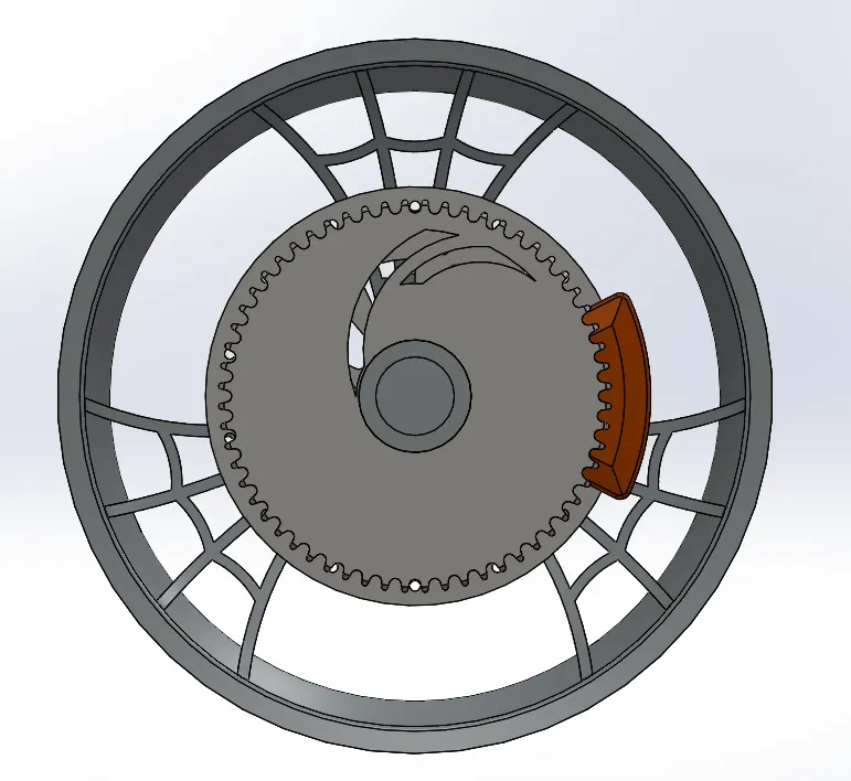
- Again Draw a Sketch on the sprocket and make use of Extruded Cut command and Use Circular pattern for the two sketches drawn.
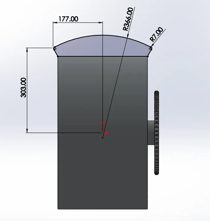
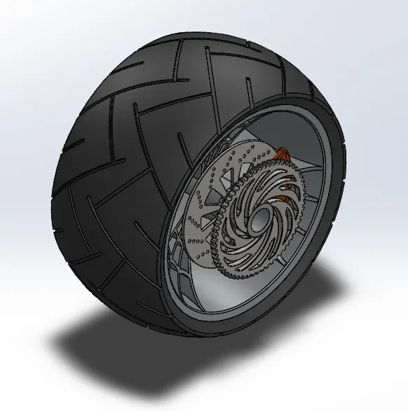
- Draw a Sketch on the front Plane for the Tyre profile as Shown below and use Revolved Boss.
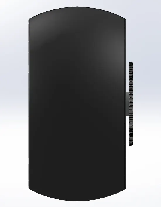
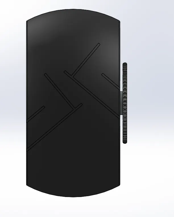
- Draw a Sketch on front Plane for the Tyre Grip as Shown below and use Extruded Cut and Circular Pattern.
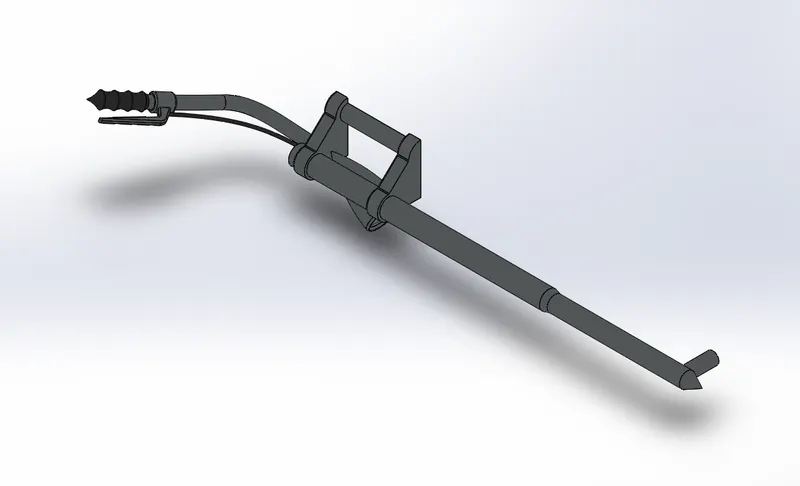
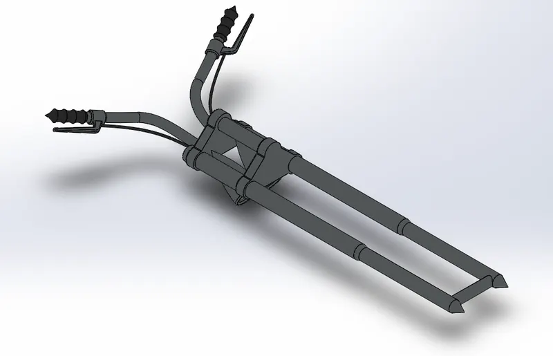
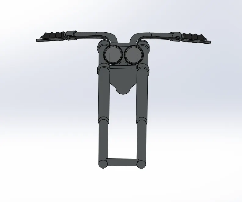
9. Front Fork
Commands Used : Revolved Boss , Extruded Boss , Linear Pattern , Projected Curve , Swept Boss , Mirror , Fillet
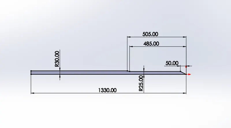
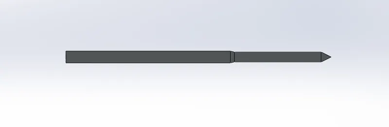
- Draw a Sketch on the Front Plane as Shown in below Fig and Use Revolved Boss.
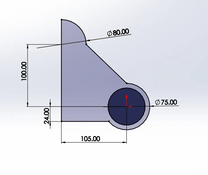
- Draw a Sketch on the Right Plane as Shown below and use Extrude Boss Command.
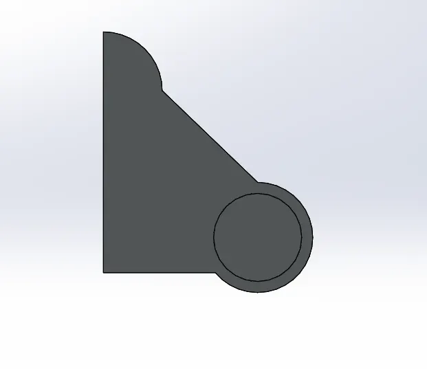
- Provide Suitable fillet for above attached fig and Linear Pattern the same.
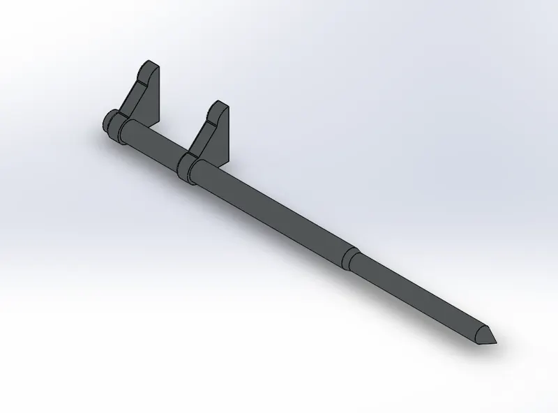
- Draw a Sketch on the Front Plane as Shown in below Sketch and use MidPlane Option.
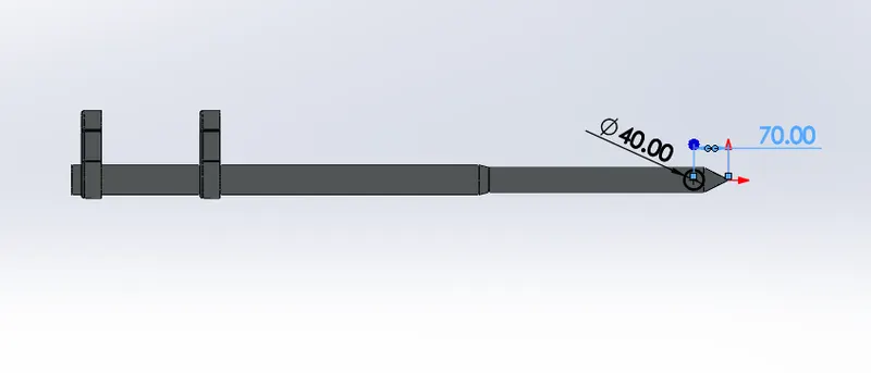
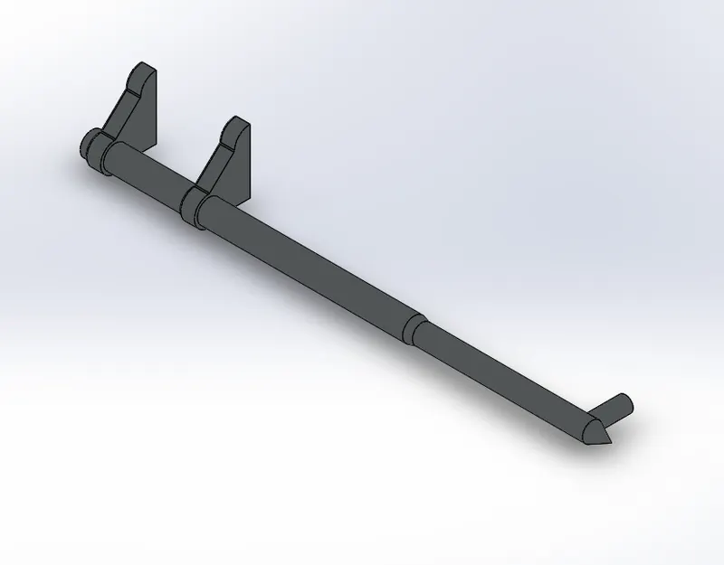
- Draw a Sketch on the Linear Patterned Component face as shown below and Extrude it.
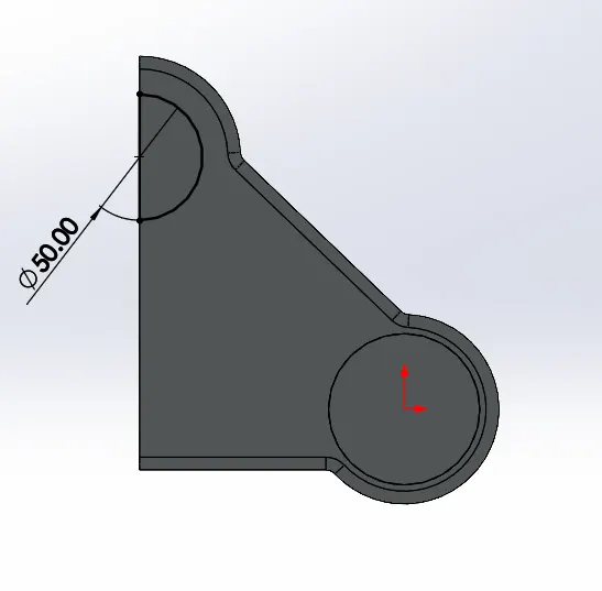
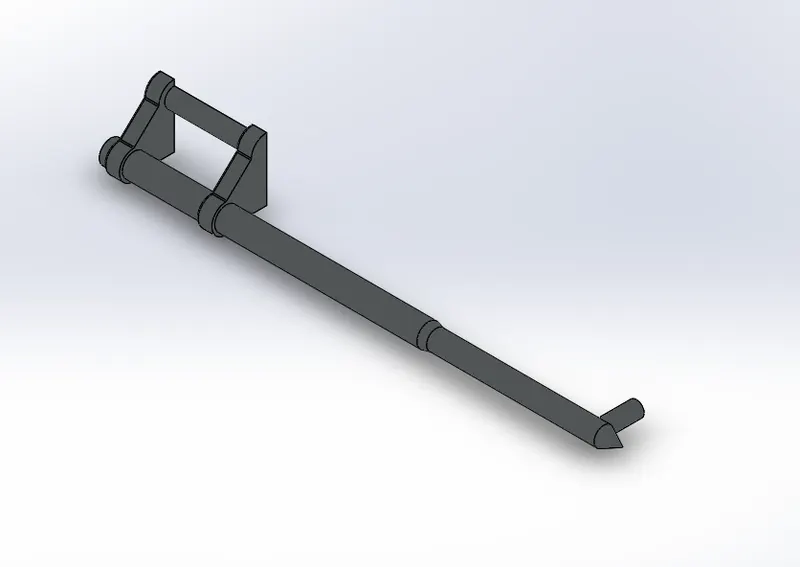
- Draw a Sketch on Front Plane as Shown below and use Revolved Boss Commnand for Lamp Light.
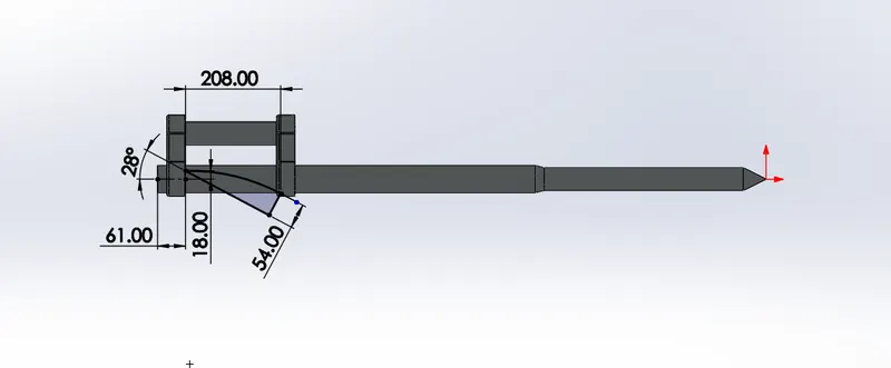
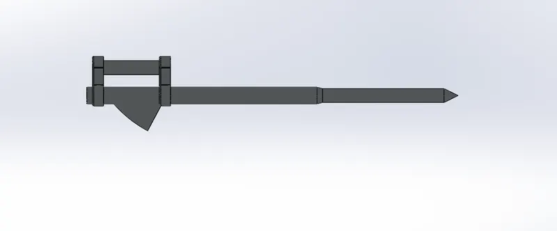
- Provide Cut Extrude as Shown below and use Fillet and Dome Option for the same.
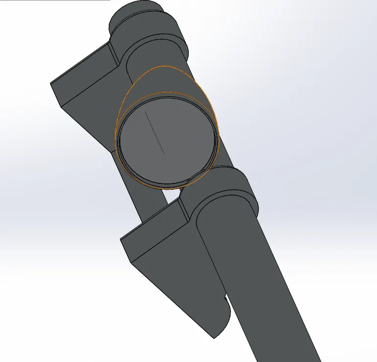
- Provide Cut revolve as shown in below fig
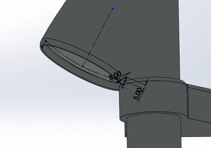
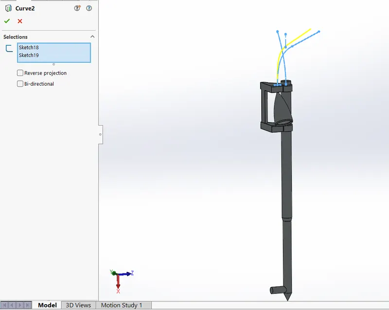
- Draw a projected Curve By using Front Plane and Top Plane as Shown in below fig.
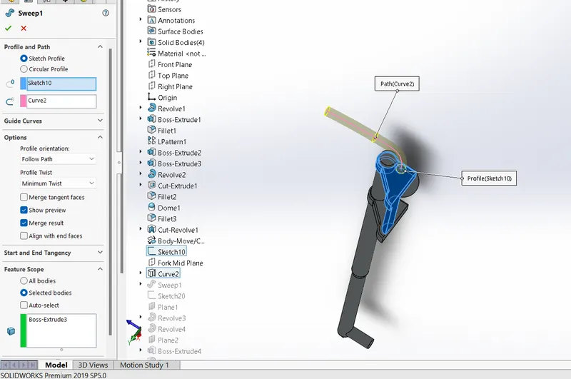
- Use Swept Boss as Shown in the Below image and make the handle.
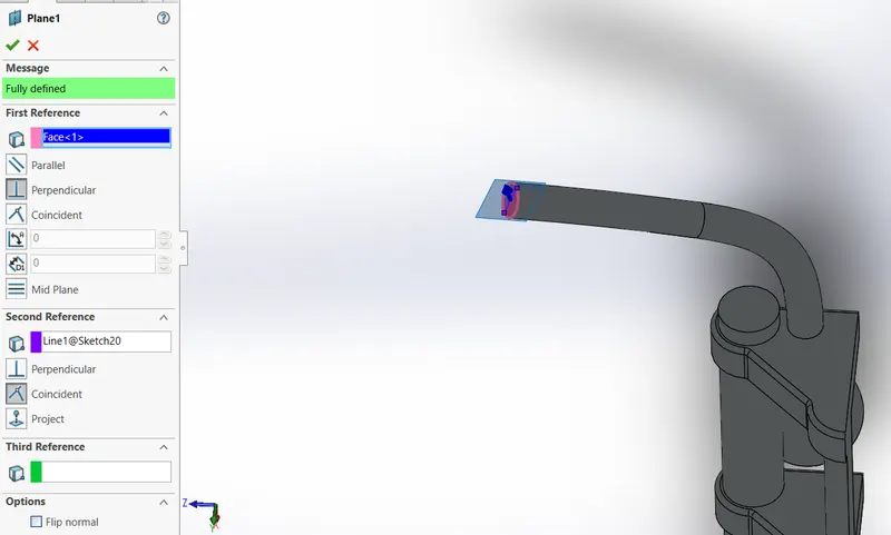
- Create the Plane on the handle as shown in the below image.
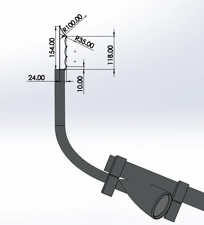
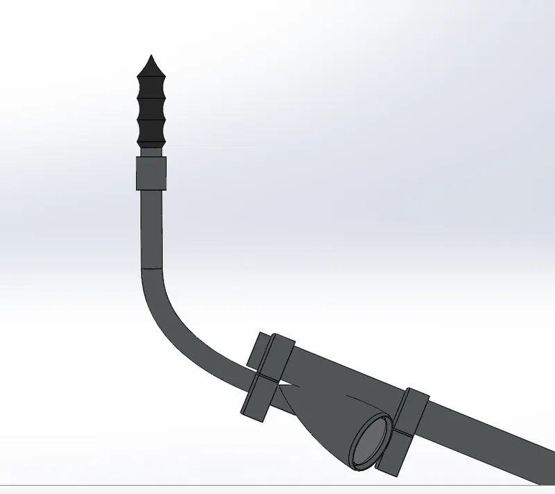
- Make the sketch on the handle for the revolved boss as Shown below.
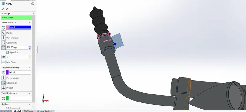
- Create Reference Plane as Shown Below for Drawing the Break Lever.
- Draw the Sketch on the refernce plane created as Shown below and provide suitable fillets.
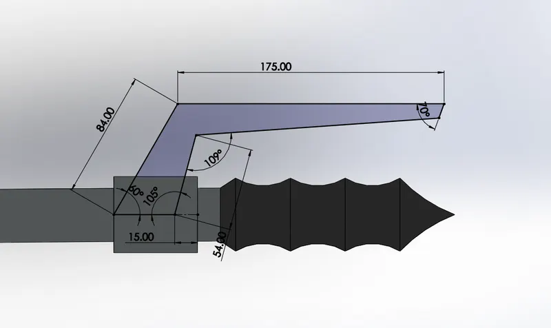
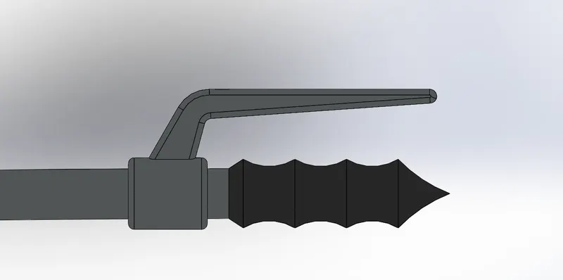
- Use Projected Curve as Shown Below for the cable wire and make Swept Boss For The same.
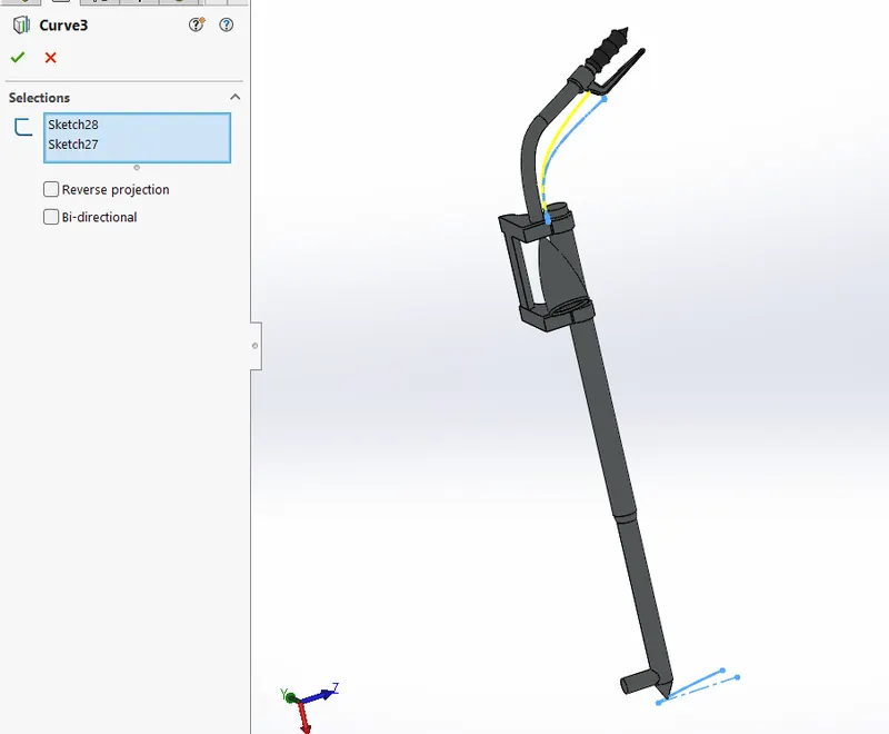
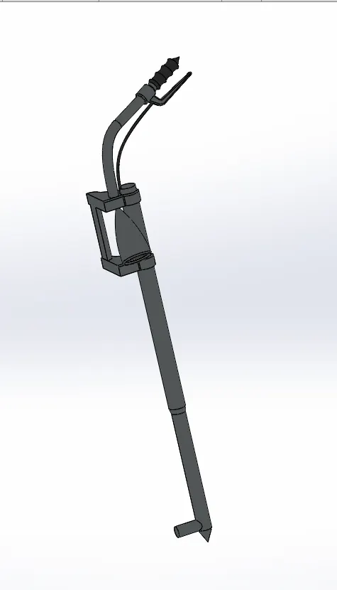
- Mirror the selected components and combine them.
10. Chassis
Commands Used : Sketch Picture , Line , Spline , CenterLine , Boss Extrude , Cut Extrude , Chamfer , Fillet , Projected Curve , Dome, Mirror , Split , Combine.
Rename Planes as Follows,
Front Plane as Midplane Chassis
Top Plane as Bottom Plane Chassis
- Go to Tools > Sketch Tools > Sketch Picture and insert the required picture
- Draw Projected Curve by using two Sketches one from Midplane chassis and another from Bottom plane chassis.
- Use Swept boss by Drawing a Sketch on the Plane and make use of the swept command and mirror the component.
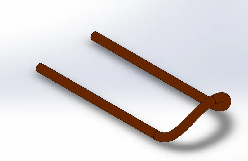
- Use Right plane and make a Sketch and use the Boss Extrude command as shown below.
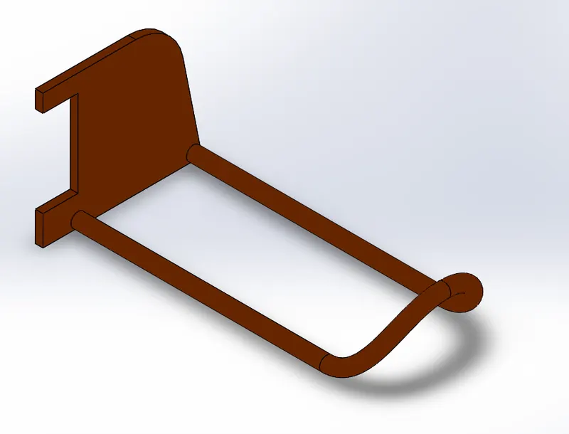
- Provide the cut extrude as shown below and give Suitable Chamfers and Fillets.
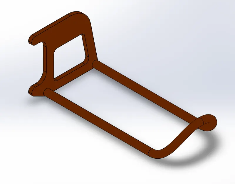
- Using Swept Boss Create the Desired profile as Shown below.
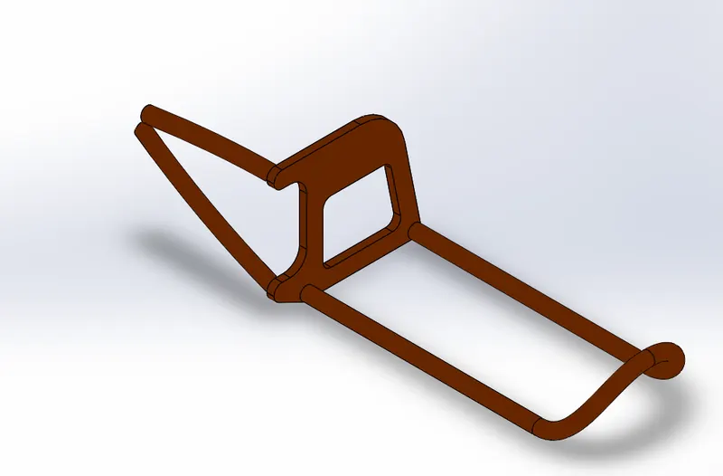
- Use Boss Extrude and Dome for creating the required dimension as below.
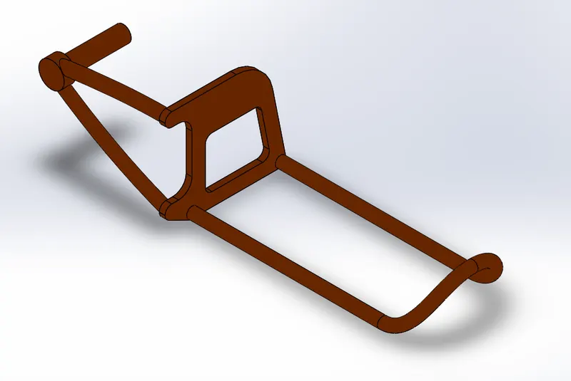
- Again the Swept boss command is used for obtaining the desired frame as Below.
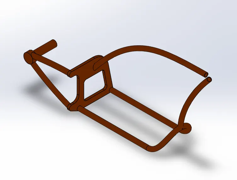
- Use Split and Combine for making the Frame into one component and Use revolved base for making Handle Geometry.
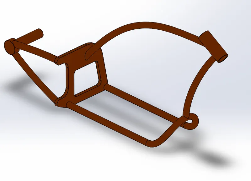
- Next the Boss Extrude is used to make the basement of the Chassis
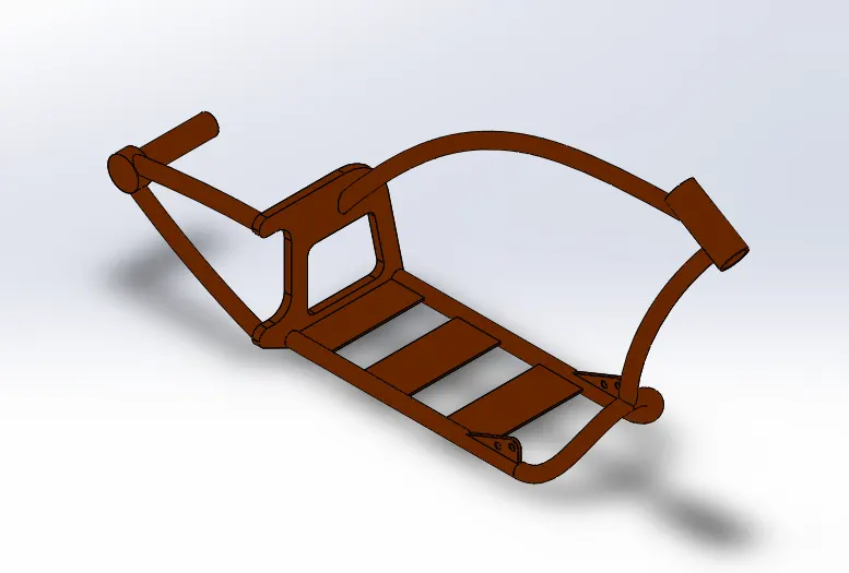
- Use Boss Extrude for making the placement for the kickstand support.
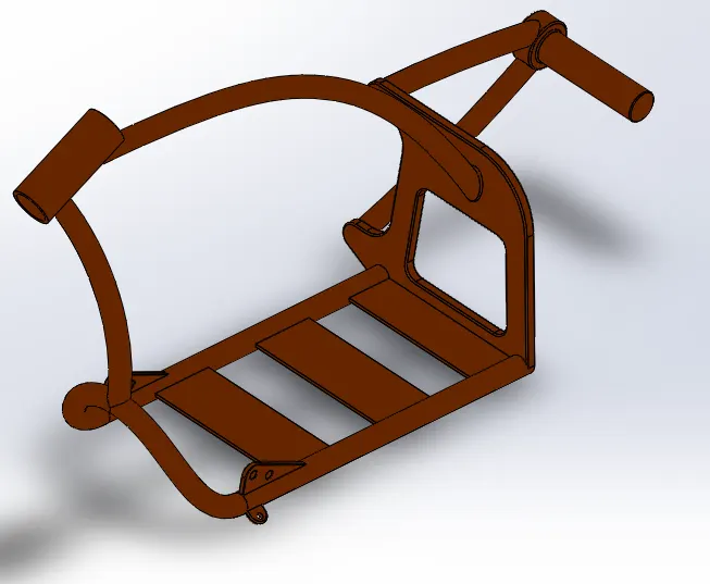
- Below View Shows the Final Chassis.
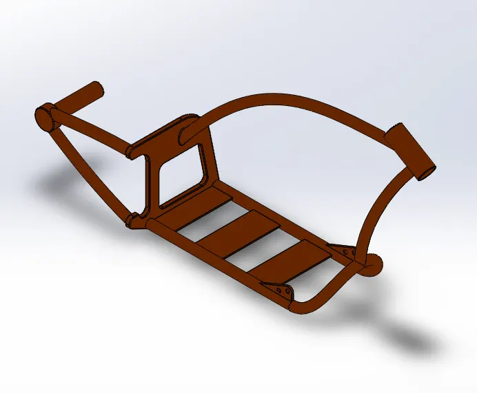
11. Engine
Commands Used : Sketch Picture , Line , Spline , CenterLine , Boss Extrude , Cut Extrude , Chamfer , Fillet , Projected Curve , Dome, Mirror , Split , Combine , Composire Curve.
- Go to Tools > Sketch Tools > Sketch Picture and insert the required picture.
- Draw and Extrude the sketch on front plane as shown below.
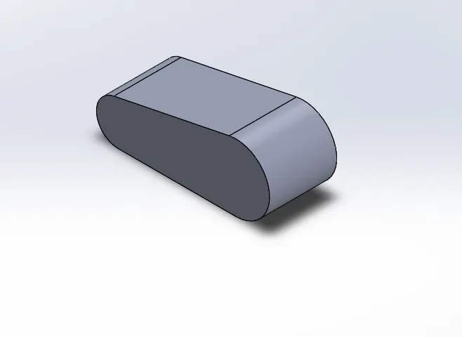
- Boss Extrude using the same sketch and extrude it as below.
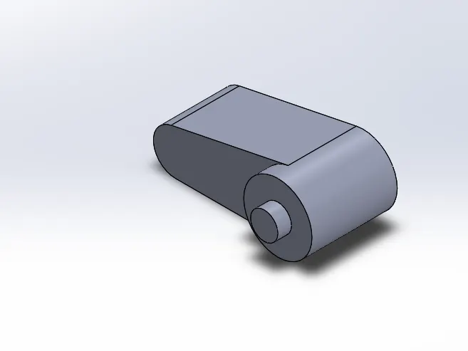
- Boss Extrude as below and provide the suitable fillets.
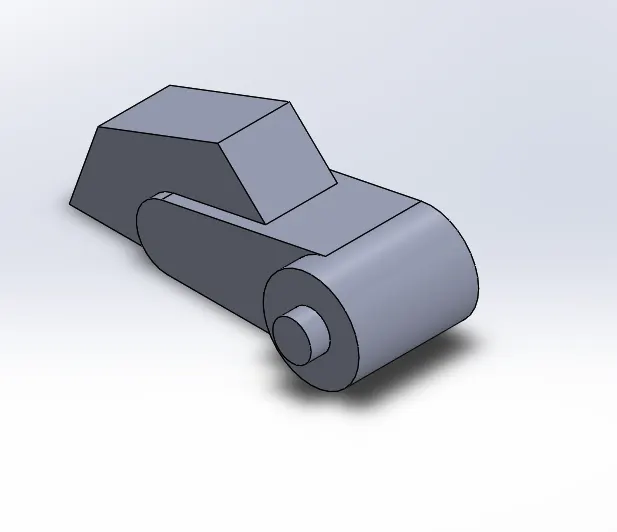
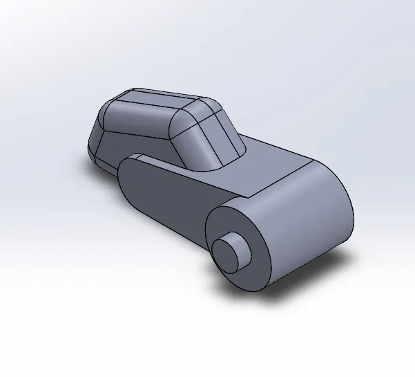
- Use reveloved Boss as shown in below fig.
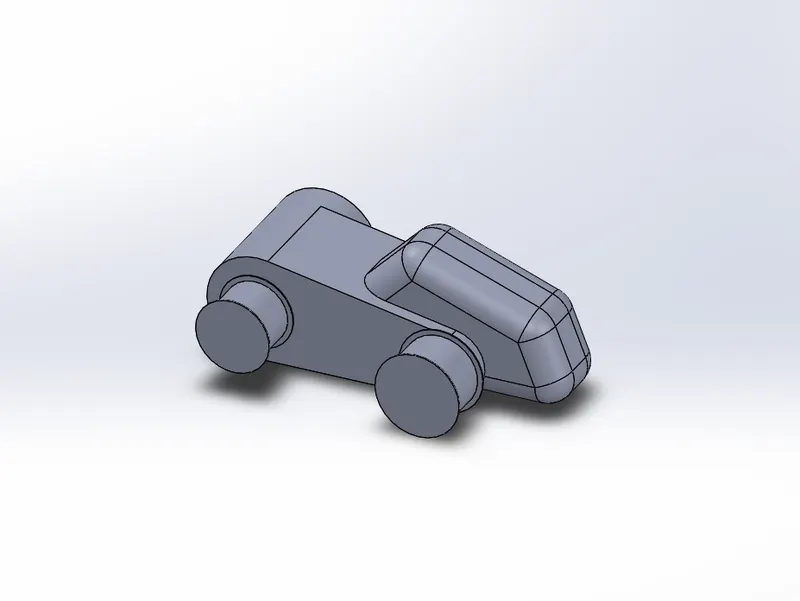
- Boss Extrude and Use Circular pattern as shown in below fig.
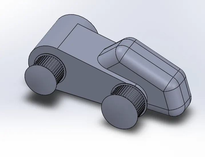
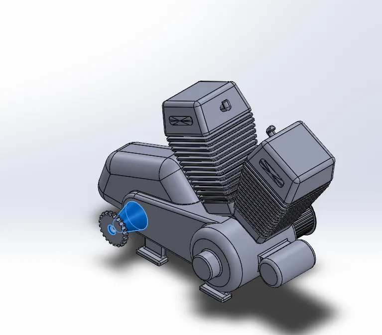
- Create Holes fillet and chamfer on the Pulley Driver.
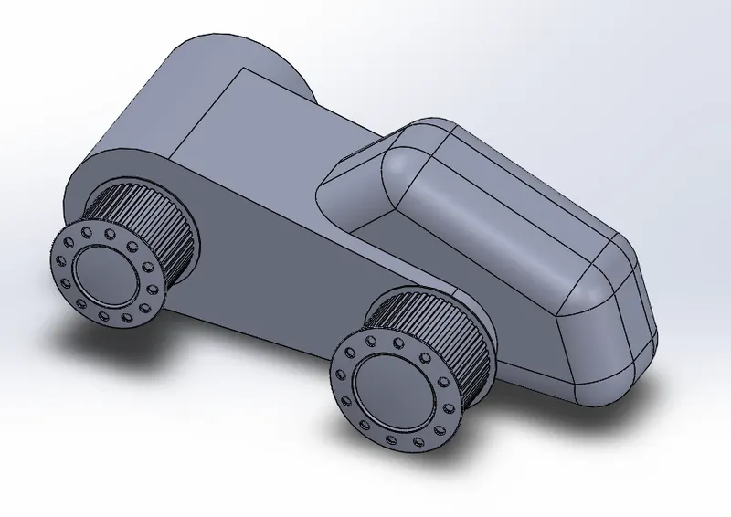
- Boss Extrude as shown in the below fig.
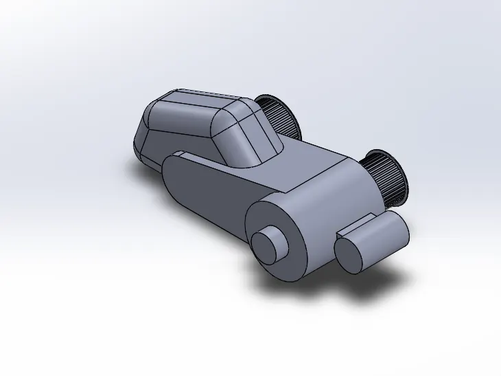
- Create Boss Extrude of the Engine Head with Draft option as shown in fig.
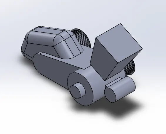
- Add another Boss Extrude with the same sketch on top of the Engine Head.
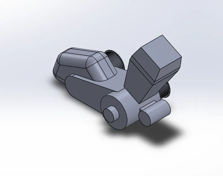
- Provide cut Extrude for the Engine for the Air Vents as shown below and provide suitable fillets.
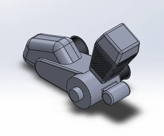
- Create Boss Extrude and provide dome as shown in below fig.
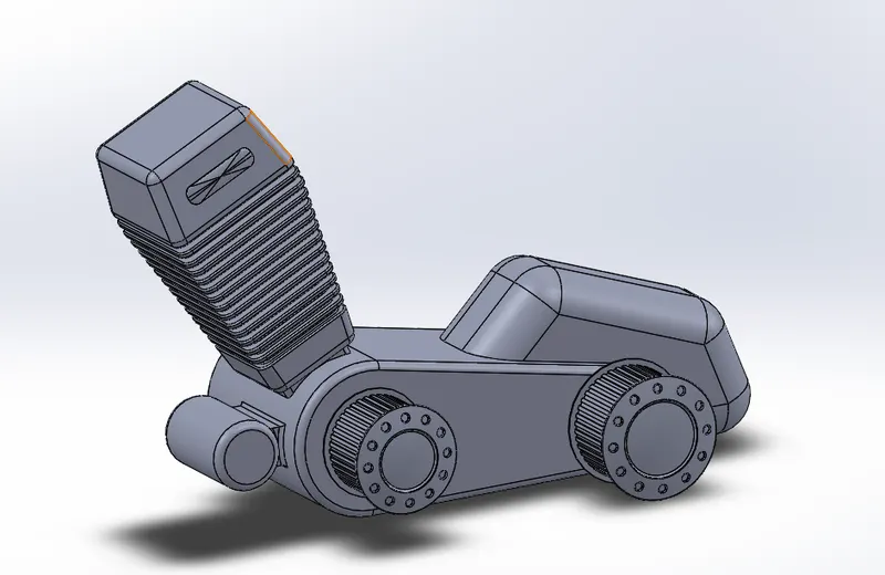
- Also use Extrude Boss for the Spark Plug.
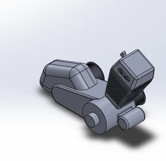
- Mirror the Engine Head on other side of the engine.
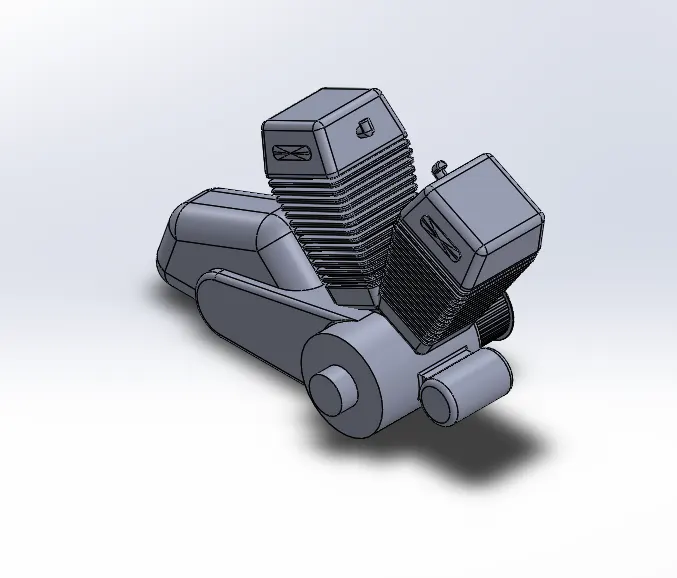
- Make Boss Extrude , Chamfer and Circular pattern for the Engine base as shown in below fig.
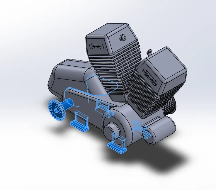
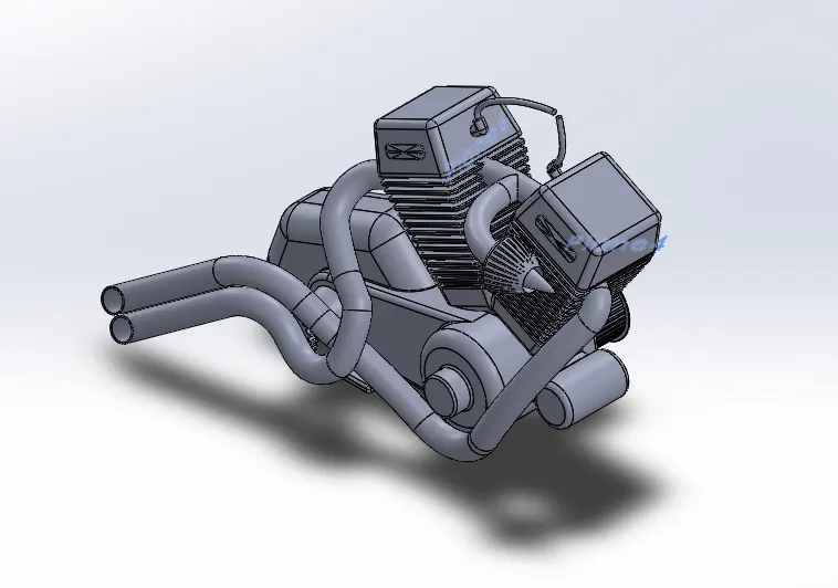
- Use Projected Curve , Composite Curve and Swept Boss for making the Complete Exhaust for the Engine as shown in below fig.
12. Gas Oil Tank
Commands Used : Sketch Line ,Smart Dimension ,Surface Sweep , Surface Trim , Surface Loft , Sweept Cut , Shell , Boundary Surface , Surface Knit, Fillet, Projected Curve.
Rename Planes as below
Front Plane as Midplane Fuel Tank
Top Plane as Bottomplane Fuel Tank
RightPlane as Right Plane Fuel Tank
- Use Surface Sweep option for the Gas oil tank
- Use Surface Trim for the removal of unwanted Surface
- Use Projected curve option for the creation of one curve using two curves from two planes.
- Use Boundary surface and lofted surface for the Closing of the opened counters in the surface of the component.
- Make Sweep Cut for the fixing of the handle to the Gas Oil Tank.
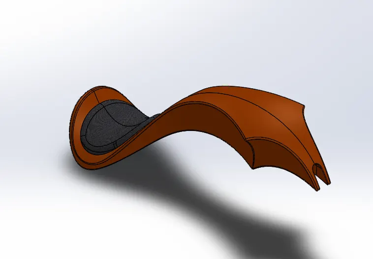
- Final Display of Gas oil Tank is seen as below fig.
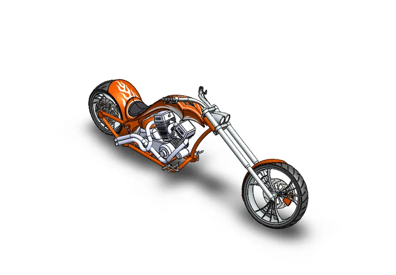
Assembly of American Chopper
The Final assembly of American Chopper after applying Decals Looks as below image
Rendered Images of American Chopper.
1.Using Photoview 360.
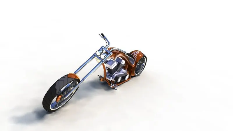
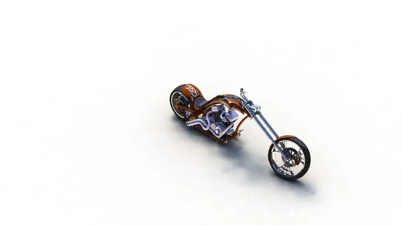
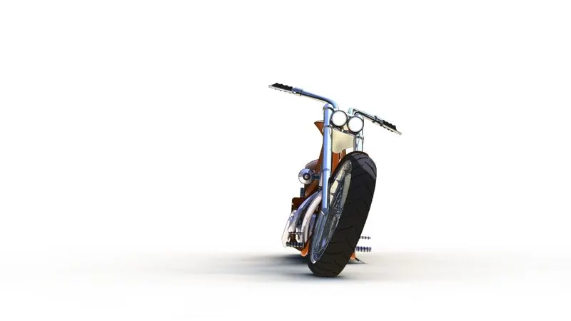
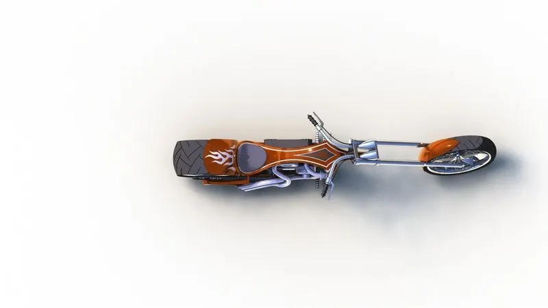
Rendering using Solidworks Visualize.
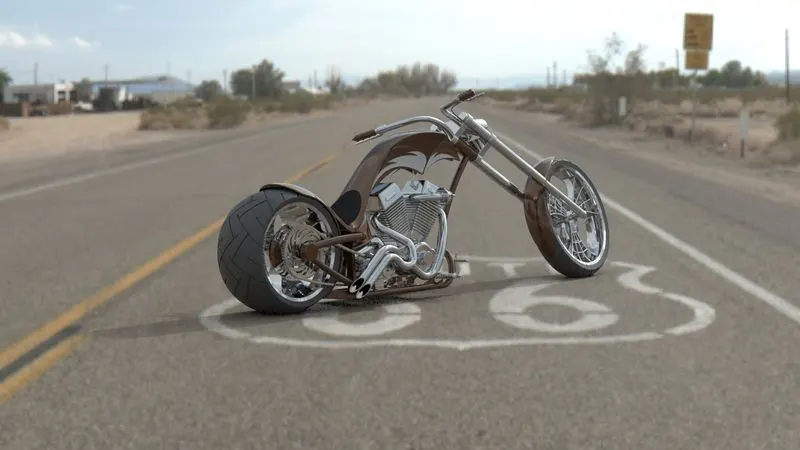
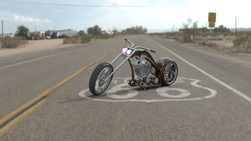
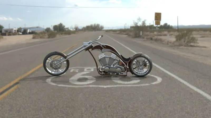
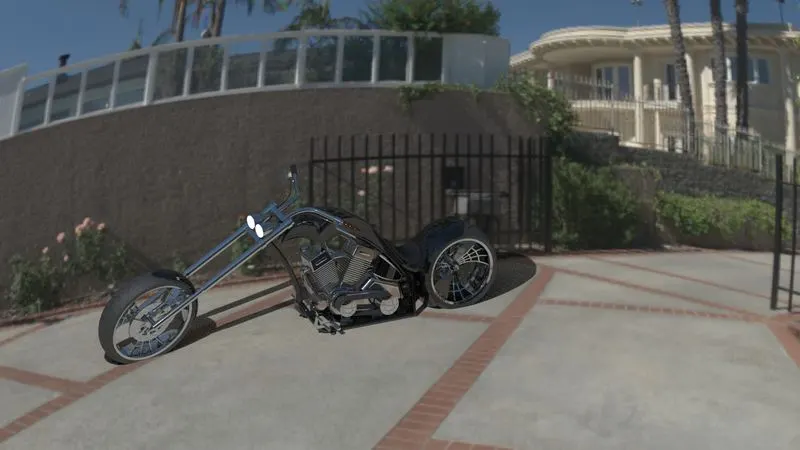
Conclusion :
After Completion of the project Building of an American Chopper We will understand the basic sketching methods in Solidworks and also the Working environment and Tools in the Solidworks and will get an understanding how to build and develop any product from Scratch and make them Dimensionally correct and good looking using Solidworks.