Photo Realistic Rendering
REPORT ON ASSEMBLY OF CHOPPER MODEL
DESIGN OF AMERICAN CHOPPER USING SOLIDWORKS
OBJECTIVE
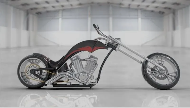
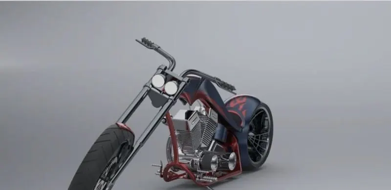
The objective of the project is to model an AMERICAN CHOPPER using a CAD (computer aided drafting) software-SOLIDWORKS and to render it with SOLIDWORKS visualize to create a photorealistic view of it.
INTRODUCTION
This project explains the designing of American chopper using the CAD software SOLIDWORKS from sketching the parts and modelling them to final rendering of the assembly to give a photo realistic view.
METHODOLOGY
• Part Modelling
• Assembly
• Rendering
PART MODELLING
In part modelling, first the 2D sketch of the part is sketched using the tools in sketch tab and then the 2Dsketch is converted into a 3D part using features in the features tab.
FEATURES USED
Boss Extrude: This feature is used to expand the object in 3D according to sketch plane.
Extrude Cut: Extrude cut feature used to cut/remove the 3d object in linear path according to sketch.
Fillet: Fillet is a feature used for making round internal or external edges to avoid sharp edges and make it smooth.
Lofted Boss/Base: Lofted boss is a feature used to achieve Complex Shapes. It does this by interpolating surfaces between various cross-sections of a model. These cross-sections can be sketches, faces, or edges.
Split: Split tool is used to split single solid part into two solid parts. It is used to project an entity onto other surfaces or curved/planar faces.
Dome: Dome is a feature used to make dome shaped extrude including elliptical dome.
Shell: Shell feature is used to make to hollow space in solid part by selecting outer wall of the solid part and so removes the inner parts. It is also used to reduce the specific thickness.
Combine: Combine tool is used to make integration of two solid parts which intersect each other as same solid part.
Chamfer: Chamfer is used to make a sharp edge or corner slightly tapered rather than being a perfect square.
Revolve cut: Revolve cut is used to cut or reduce the
extrude of cylindrical round surface.
Move/copy body: This feature is used to move/copy the 3D body to one place to another place.
Mirror. Mirror is used to mirror a feature or body by
reference of the selected plane.
Sweep: This feature is used to sweep any kind of fully defined sketch along with the path.
Sweep cut: Sweep cut is same as sweep feature but its directly proportional to sweep which makes a cut along with the sweep path.
Swept Surface: It is used to make a surface along with a path the curve is driven.
Boundary Surface: Boundary surface is used to make a surface in between two finished surfaces.
Loft Surface: Loft surface is used to make loft in
between two profiles along with guide path.
Knit surface: knit surface is used to knit the two free edges or open edges of the surfaces together also it reduces the gap between the two edges of the surface.
Surface Trim: Primarily used to cut away material from a surface, and provides two modes: Standard and Mutual.
Projection Curve: Projection curve is a 3D curve which is projected on the basis of the two different 2D curves in two different planes.
Blocks: You can make save, edit and insert blocks from the drawing items and sketch entities that you use often such as standard notes, title blocks, label positions and so on you can attach blocks to geometry or to drawing views
ASSEMBLY
Assembly is most often referred to putting components together in an assembly line, but more specifically, it refers to creating a complete product that performs an intended function. Changes in the component are automatically reflected in the assembly i.e. The rebuild option will automatically take place or else it will ask the user to rebuild the document.
ASSEMBLY APPROACHES IN SOLIDWORKS
• Top-Down Approach • Bottom-Up Approach
RENDERING
Rendering or image synthesis is the automatic process of generating a photorealistic or non-photorealistic image from a 2D or 3D model using a computer program. The resulting image is referred to as the render.
MAJOR CATEGORIES IN RENDERING
• Real-Time Rendering
• Pre-Rendering
SOFTWARE USED
• Photoview 360
• Solidworks Visualize.
COMPONENTS DESIGNED
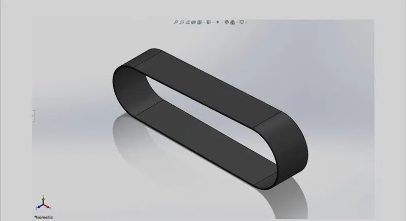
• Transmission Belt
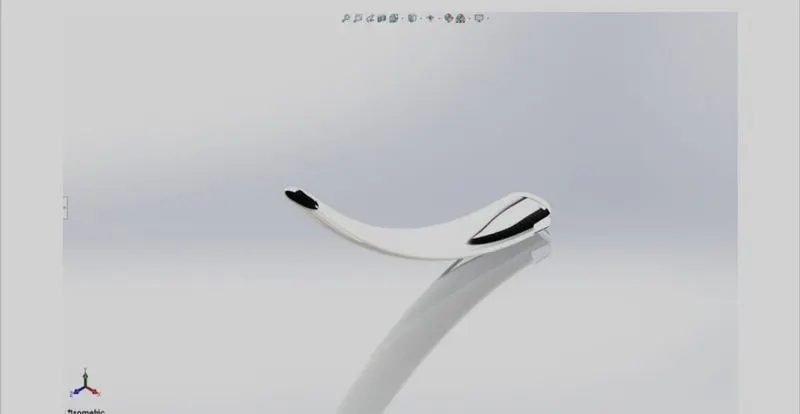
kick stand
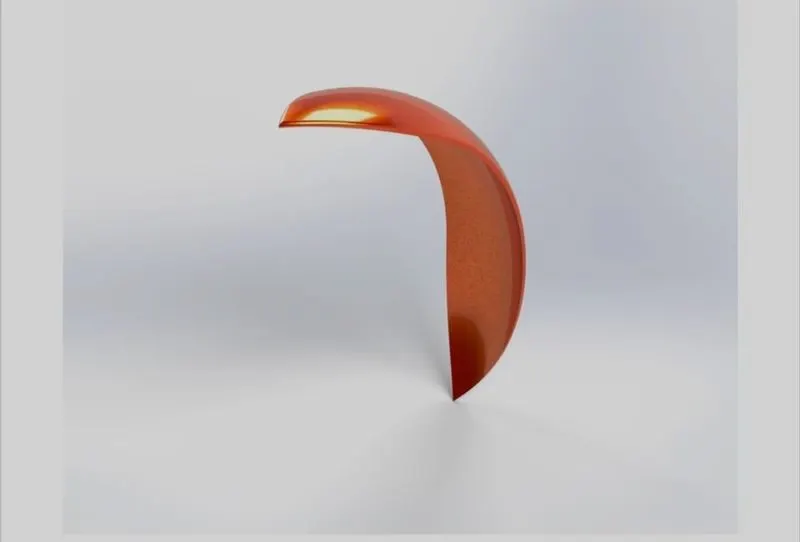
front fender
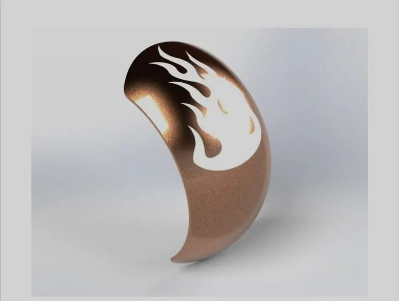
rear fender
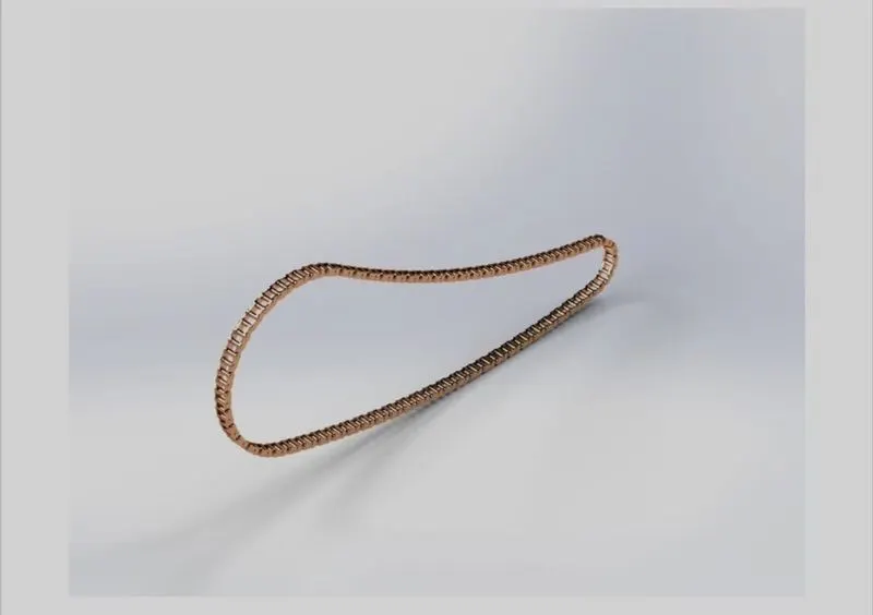
chain
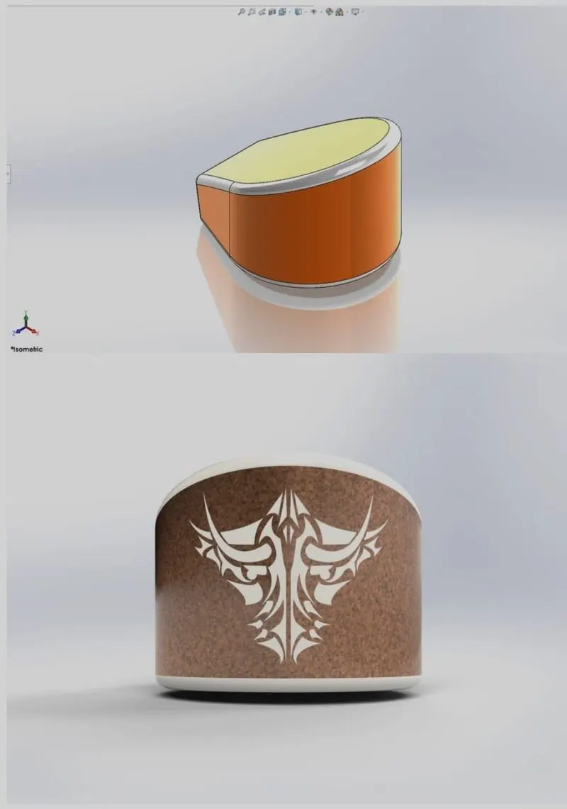
oiltank
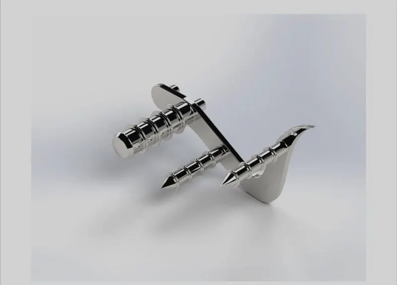
pedal
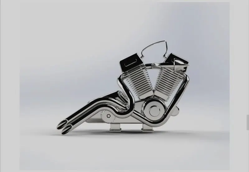
engine'
american chopper
CONCLUSION
Thus, the parts of the AMERICAN CHOPPER are designed and assembled using SOLIDWORKS and are rendered to photorealistic images using PHOTOVIEW 360 and SOLIDWORKS VISUALIZE.