Photo Realistic Rendering
AMERICAN CHOPPER 3D MODELLING & RENDERIN
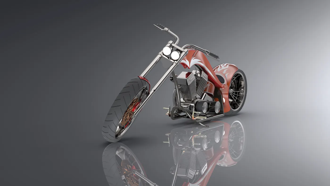
Project Name: 3D Modelling & Rendering of American chopper Motorbike.
Introduction: A chopper is a type of custom motor cycle which emerged in California in the late 1950s. The chopper is perhaps the most extreme of all custom styles, often using radically modified steering angles and lengthened forks for a stretched-out appearance. They can be built from an original motorcycle which is modified ("chopped") or built from scratch. Some of the characteristic features of choppers are long front ends with extended forks often coupled with an increased rake angle, hard tail frames (frames without rear suspension), very tall "ape hanger" or very short "drag" handlebars, lengthened or stretched frames, and larger than stock front wheels.
Objective: Aim is to create aesthetic Model of an American Chopper.
- To create a 3D model of Individual Motorbike Exterior parts.
- To Assemble the Parts.
- To create a Photo realistic Render of the motor bike.
Software Used:
- Solid Works 2018
- Solid works Visualise 2018
Design methodology
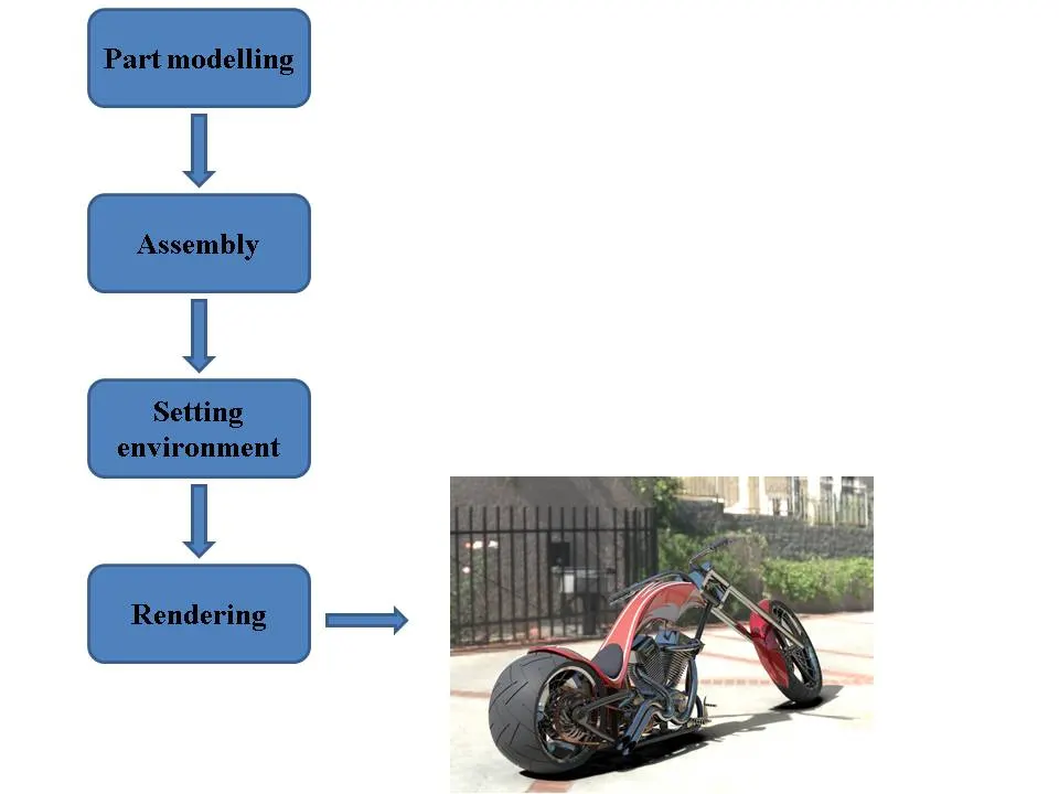
List of motorbike Parts:
- Transmission belt
- Kick stand
- Front fender
- Rear fender
- Oil tank
- Chain
- Pedal
- Front wheel
- Rear wheel
- Front fork
- Chassis
- Engine
- Gas tank
- Transmission Belt A belt is a loop of flexible material used to link two or more rotating shafts mechanically as shown in figure 1.1.
Commands used: Sketch, Extrude Boss, Offset Entities, Fillet.
Note: The Sketch drawn in the respective planes for models must be Fully Defined using important Dimensions & Sketch Relations applied Ex: Parallel, Concentric, and Tangent etc…
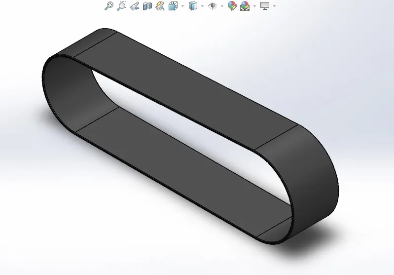
Figure 1.1
2. Kick stand
A kickstand is a device on a motorcycle that allows the bike to be kept upright without leaning against another object or the aid of a person, The is as shown in figure 1.2.
Commands used: Sketch, Lofted boss, Dome, Extrude cut, Split body, Fillet.
Note: The Sketch drawn in the respective planes for models must be Fully Defined using important Dimensions & Sketch Relations applied Ex: Parallel, Concentric, and Tangent etc…
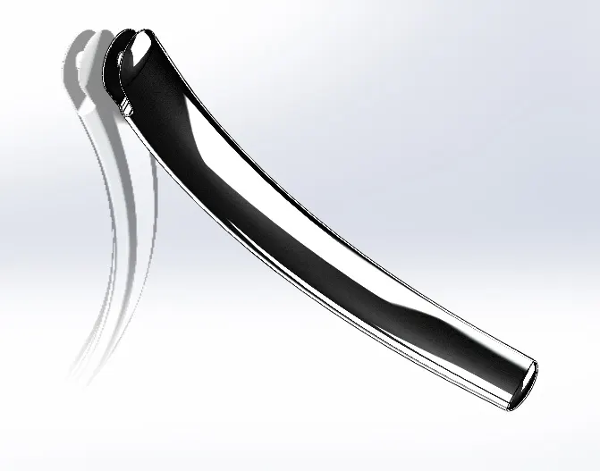
Figure 1.2
3. Front fender
These mudguards are fixed over the front tire of the bike. It protects bike rider from water and mud caused to thrown up by the bike.
Commands Used: Sketch, Offset entities, Revolve boss, Split body, Fillet.
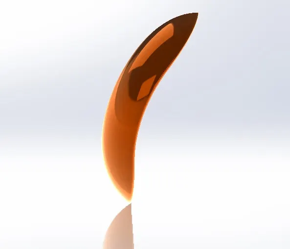
Figure 1.3
4. Rear fender
These mudguards are fixed over the rear tire of the bike. It protects bike rider from water and mud caused to thrown up by the bike.
Command Used: Sketch, Offset Entities, Revolve boss, Split body, Fillet, Shell.
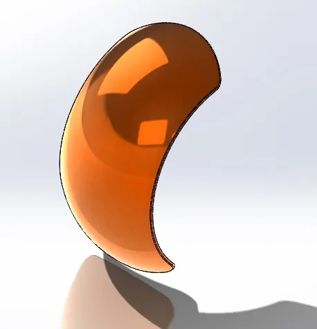
Figure 1.4
5. Oil tank
Stores oil for Lubricating engine parts & helps engine to cool.
Commands Used: Sketch, Extrude boss, Combine, Fillet, Shell.
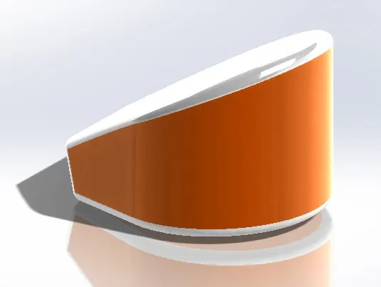
Figure 1.5
6. Chain
Chain drive is a way of transmitting mechanical power from one place to another. It is often used to convey power to the wheels of a vehicle, particularly bicycles and motorcycles
Commands used: Sketch, Make block, Extruded boss, Fillet, Curve driven pattern, Mirror.
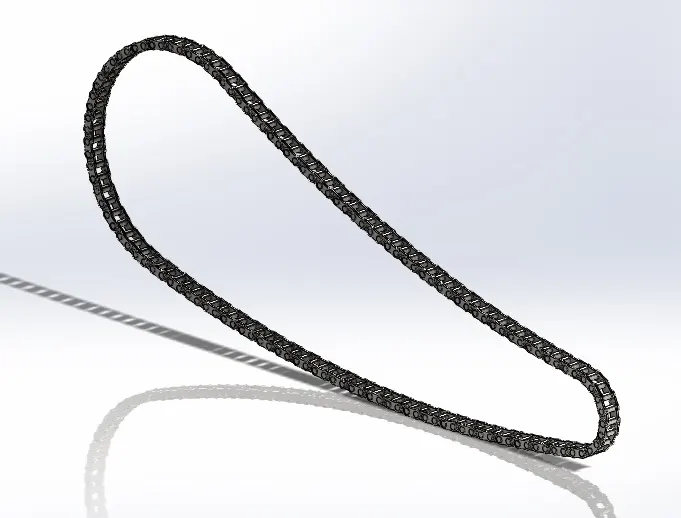
Figure 1.6
7. Pedal
It is an external part attached to motorcycle, used for foot placing, applying of brakes & gear shifting.
Commands used: Sketch, extruded boss, Fillet, Revolve boss, Dome, Chamfer, Linear pattern.
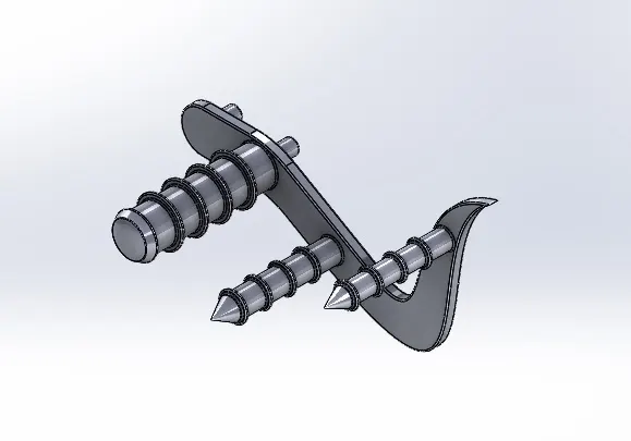
Figure 1.7
8. Front wheel
As the name specifies front wheel will be mounted to the front axel of the motorcycle, & it consist of brake caliper.
commands used: Sketch, Offset entities, convert entities, Trim entities, Revolve boss, Extruded boss, Extrued cut, Revolve cut, circular pattern, Combine, Fillet, Pattern.
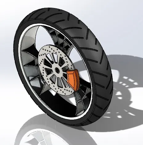
Figure 1.8
9. Rear wheel
The wide rear wheel consist of spider web shape rim, tyres, brake, rotor, caliper & sproket.
Commands used: Sketch Offset entities, Convert Entities, Trim enitites, Revolve boss, Extrude boss, Extrude cut, Revolve cut, Circular pattern, Combine fillet, Chamfer.
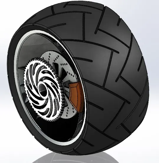
Figure 1.9
10. Front fork
A motorcycle fork connects a motorcycle's front wheel and axle to its frame, typically via a yoke, also known as a triple clamp, which consists of an upper yoke joined to a lower yoke via a steering stem, a shaft that runs through the steering head, creating the steering axis.
Commands used: Sketch, Revolve boss, Extruded boss, Fillet, Linear pattern, Extruded cut, Dome, Revolve cut, Move/copy body, Project curve, Swept boss, Mirror, Combine.
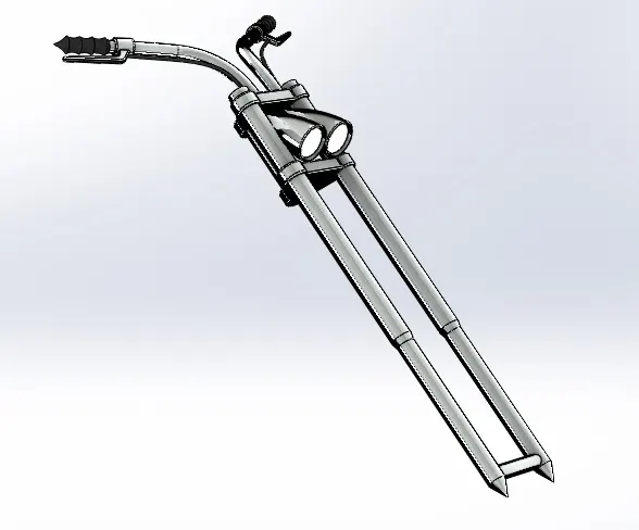
Figure 1.10
11.Chassis
A motorcycle's chassis or frame forms its skeleton. All the components of a motorcycle, like the suspension, wheels, fuel tank, seats, handlebars etc, are attached to this base structure which lends a motorcycle its strength and ability to handle well.
Commands used: Sketch, Convert entities, Project curve, Swept boss, Mirror, Extruded boss, Extruded cut, Chamfer, FIllet, Dome, Split body, Combine.
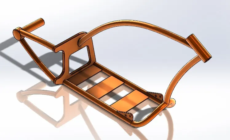
Figure 1.11
12. Engine
A V-twin engine, also called a V2 engine, is a two-cylinder Piston engine where the cylinders share a common crankshaft and are arranged in a V configurstion.
Commands used: Sketch, Convert entities, Extruded boss, Revolved boss, FIllet, Circular pattern, Dome, Extruded cut, Chamfer, Liner pattern, Mirror, Split body, Swept boss, Combine, Project curve, Composite curve.
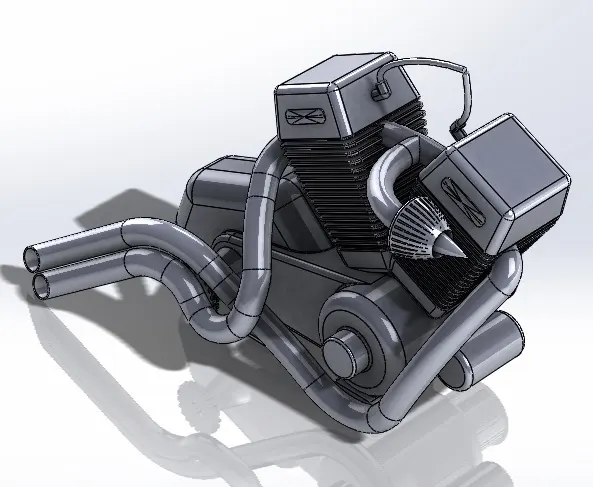
Figure 1.12
13. Gas tank
Unlike other parts gas tank was completely designed using surface modelling to match its 3D curved shapes.
Commands used:Sketch, Convert entities, Swept surface, Trim surface, Project curve, Lofted surface, Boundary surface, Mirror, Knit surface, Split line, Extruded surface, Fillet, Swept cut, Shell.
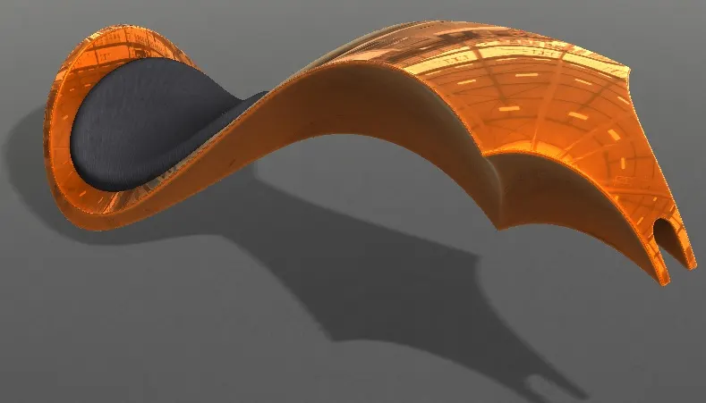
Figure 1.13
2. Assembly
After making all the parts modelling assembly of the parts to be made & as per solid works the model assembled using relations, Standard mates(Coincide, Parallel, Tangent, Perpendicular, etc,..) Advanced mates (Symmetric, Width, angle, etc,..)
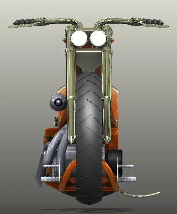
Figure 2.1 Front view of assembly
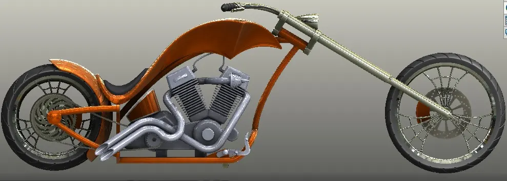
Figure 2.2 Side view of assembly
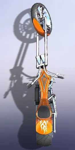
Figure 2.3 Top view of assembly
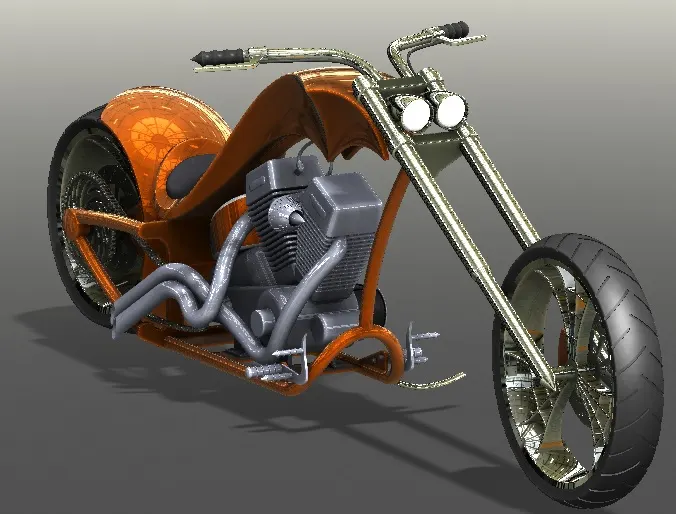
Figure 2.4 Isometric view of assembly
3.Rendering
Rendering of the model made using photoview 360 & solid works visualize
Decals were applide to gas tank, rear fender, & oil tank during final model rendering stage
Some parts like kick stand & front forks were applied with limiting angles to mimic the realistic appearance of the model
3.1 Solid works photo view 360 (addon)
Renering using photo view 360 involved setting the scene, Environment, camera perspective & lights by adjusting various parameters
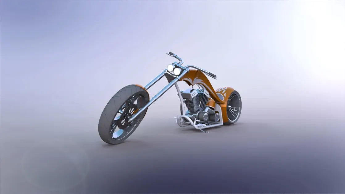
Figure 3.1 rendered image of the model
3.2 Solid works visualize
The assembly imported to solid works visualize & adjustments made for colour, environment, camera position.
Figure 3.2 Render 1 using solid works visualize
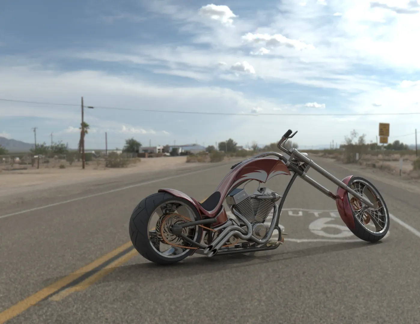
Figure 3.3 Render 2 Using solidworks visualize
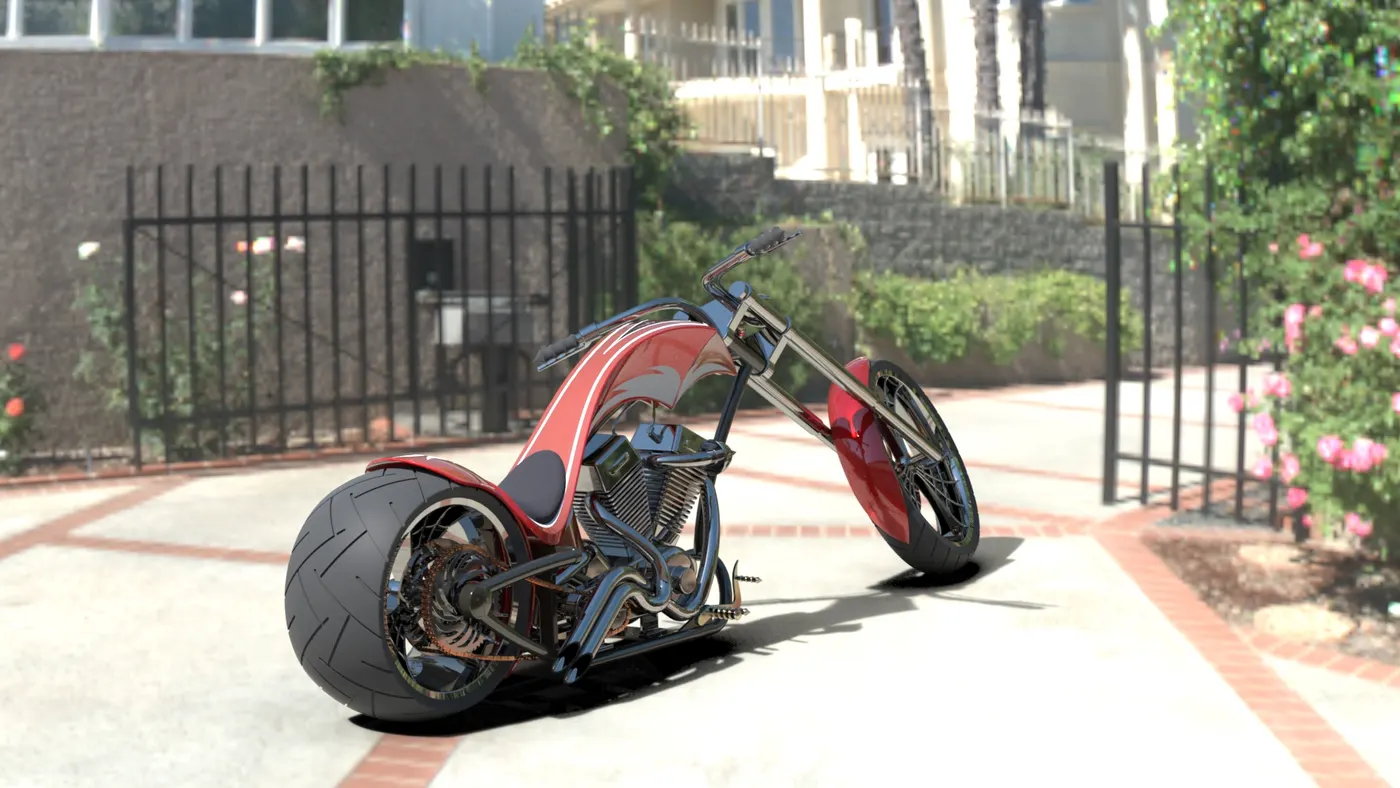
Figure 3.4 Final render using solid works visualize.
Conclusion:
Thus the design and modelling of the American chopper made using solidworks 2018 & photorealistic rendering made usind solidworks visualze.