Modelling and Rendering of an American Chopper in SolidWorks®
Modelling and Rendering of an American Chopper in SolidWorks®
Objective
To model all the parts of an American Chopper right from scratch and integrate them into an assembly using SolidWorks®, further creating a photorealistic render for the same with the help of SolidWorks® Photoview360 and SolidWorks® Visualize.
Introduction
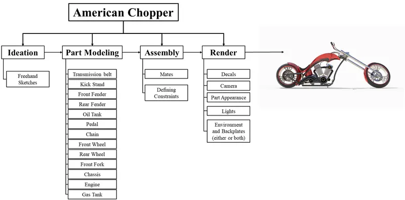
SolidWorks® is a 3D modelling software that operates on the dimension value specified making it a parametric software. At any given point in time, you can change the dimension of your model and the model will tune according to the changes made making it much more user friendly. SolidWorks® provides a variety of power tools including assemblies rendering tools and simulation. For this particular project, SolidWorks® Premium 2020 version has been used for modelling and assembly. The photorealistic rendering has been done with the help of Photoview360 and SolidWorks® Visualize. The report has been drafted from a learner’s perspective and aims to acquaint one with all the tools and features used to model an American chopper. The project aims to acquaint one with all the tools and features SolidWorks® has to offer, in form of modelling parts for the American chopper. Further learning to assemble the parts to make an American Chopper assembly and rendering it. Since the project aims to make the user learn all the tools and features, the chopper made is just a stationary assembly and just depicts how the design will look. Further, the report will dive into more tools and features used to make the parts.
Design Methodology
Part Modelling
· Transmission Belt 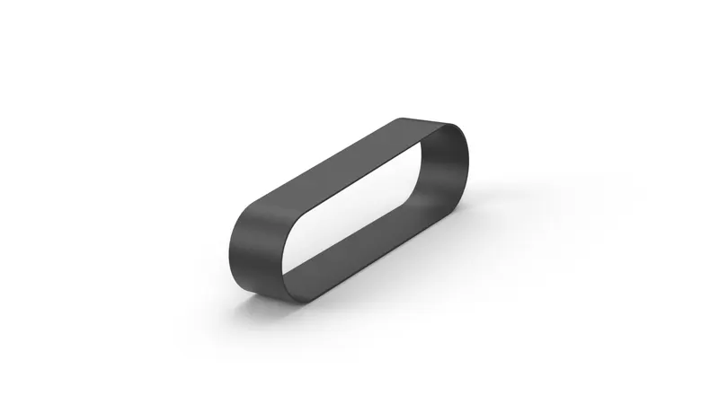
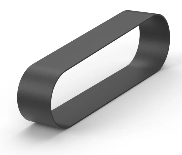
A transmission belt is a belt drive system that is used to transmit power from the engine pulley to the gearbox pulley. The belt drives are generally lightweight and much more durable. The working principle of the transmission belt is simple as it employs positive engagement of two sets of meshing teeth resulting in no relative motion between the meshed elements. This also helps to maintain a constant speed ratio. Belt drives are capable enough to transmit large torques even with high accelerations. When the selection of belt takes place, many factors such as the belt material, reduction ratio, centre distance, belt elasticity, speed etc need to be considered. For this particular project, no material has been selected but a suitable appearance of rubber has been given to give a realistic look.
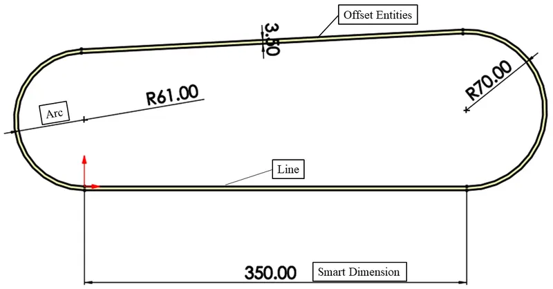
Line Tool  : Used to sketch straight lines. Can also construct a midpoint line and construction line which can be used for reference while sketching. While sketching if the cursor hovered over the endpoint of the line, will result in creating an arc.
Offset Entities : Creates offsets for one or more sketches by a specified distance.
Smart Dimensions : Smart dimensions is used to add or edit dimensions of a particular sketch or any entity.
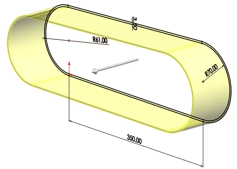
Boss Extrude : Boss extrude feature extrudes a closed sketch in one or two directions. It offers a variety of options to get the exact profile as intended. The options are blind, offset from surface, up to vertex, up to surface, up to body, midplane. These aids the user in achieving the exact desired profile that is required.
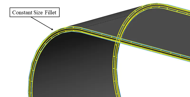
Constant Size Fillet : This feature allows the creation of a rounded internal or external face along the edges. The constant size fillet as the name suggests offers a symmetrical constant size rounded portion along the edge.
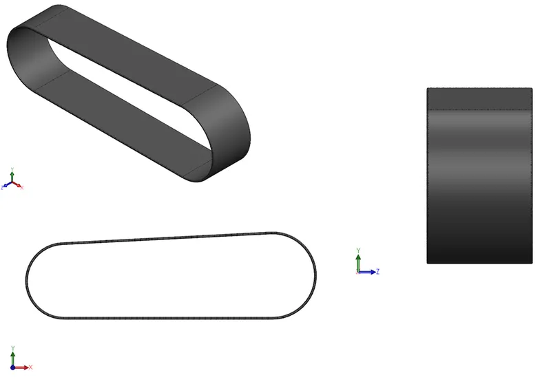
Views and Rendered images are displayed below.
· Kickstand 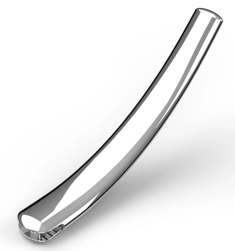
The kickstand supports the chopper in a stationary position allowing the chopper to be upright. It needs to be made from a sturdy material as it needs to support the whole weight of the chopper. The kickstand is lifted when the chopper is moving. For this project, it has been given a chrome appearance just to add a more aesthetic look to the chopper.
Tools and features used are mentioned below. Smart Dimension, constant sizer fillet and boss extrude features have also been used in the making of kickstand and their functionality has already been explained in the previous portion.
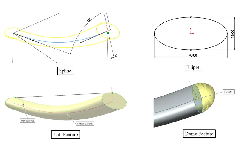
Ellipse  : Sketches an ellipse by placing the center point and defining the other two axes.
Spline  : Helps to create very complex curve geometry, simple curves which are continuous in nature.
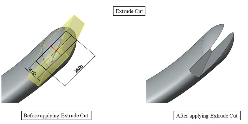
Center Point Rectangle : Enables creating a rectangle just by placing the midpoint and dragging it to a point of the desired length.
Lofted Boss : Creates a path of material between two given sketches. Requires a guide curve/line to guide the path of the material between the two profiles. Complex geometry can easily be handled with this tool.
Elliptical Dome : Creates an elliptical-shaped dome-like structure at the face end.
Extruded Cut  : The removal of material from any solid body made can be done with the help of extruded cut. The material can be removed in various ways as intended by the user. Options provided by the extruded cut include Blind, through all, through all both, up to next, up to vertex, up to body, up to surface, offset from surface, midplane.
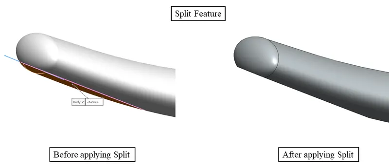
Split  : Split feature is very handy and makes the work a lot easier. It can create multiple bodies from a single solid body. If consume bodies is selected it can remove that particular portion from the solid body.
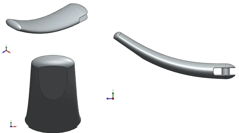
Views and Rendered Image are displayed below.
· Front Fender 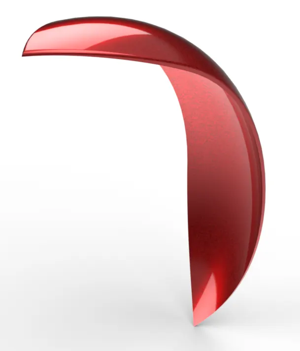
Front fender usually made of sheet metal act as a shield for the debris that flies off from the road due to the rotation of the tire. Also known as the mudguard and serves the same purpose as the name. For a normal motorbike, this just serves as the barrier, but when the chopper culture is considered, it is usually a great way to display art and creativity. The trimming of fenders in different shapes and glossy paint gives a much aesthetic look to the chopper.
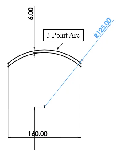
3 Point Arc : 3 point arc draws arc which is specified by the two endpoints and the radius.
Revolve : It revolves a sketch around an axis in order to create a solid feature.
Line, offset entities, spline, split, fillet were among other features used to create the front fender.
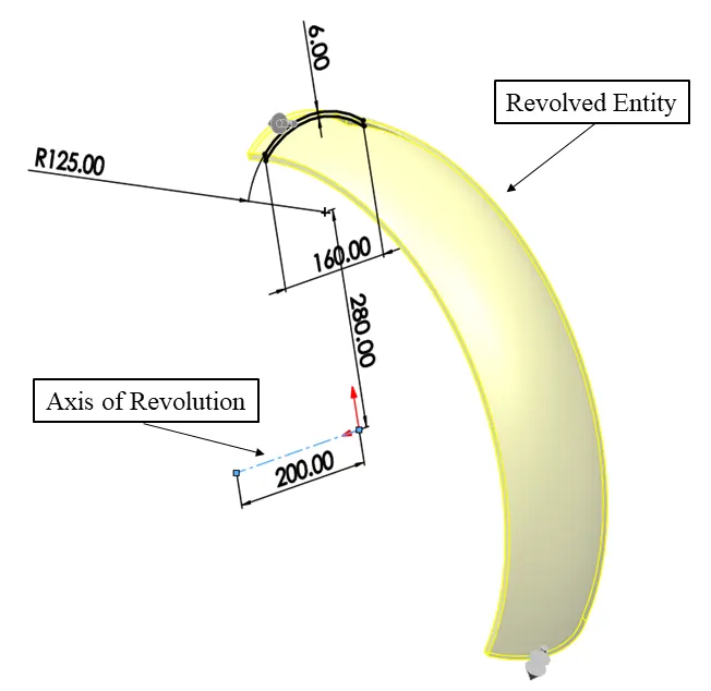
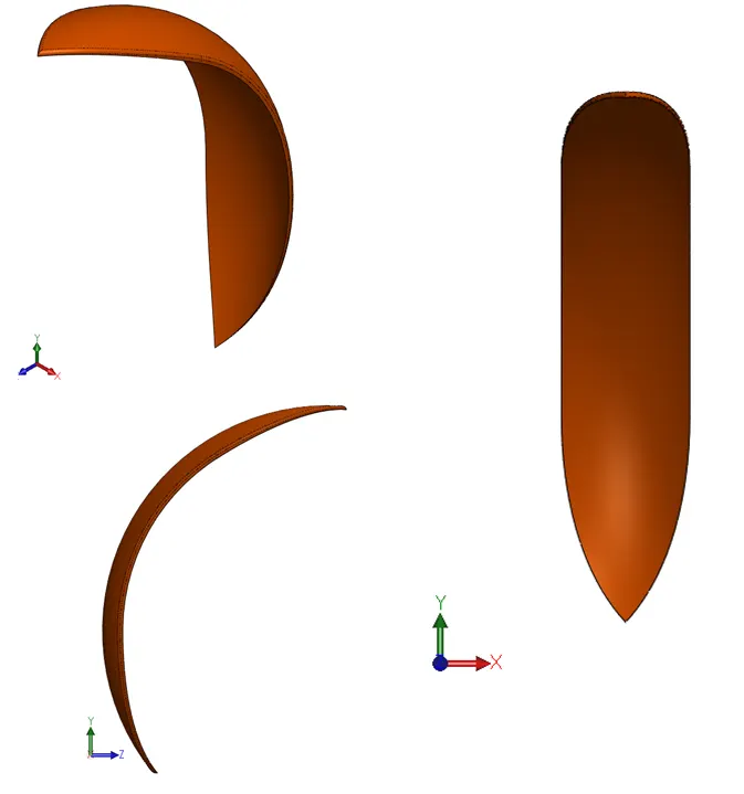
Views and rendered images are displayed below.
· Rear Fender 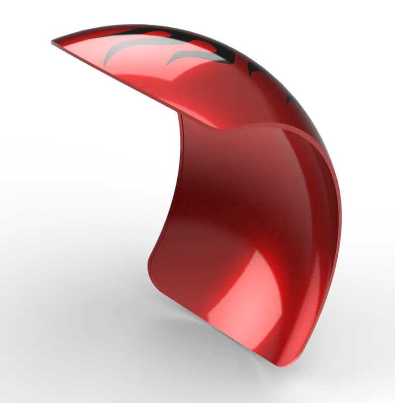
The rear fender also serves the same purpose as the front fender which is protecting from road debris. It also helps to keep the chopper clean as the rotating tire may splash water towards the rider from the back. In chopper culture, this also plays a great role in displaying art and aesthetics. A kind of low stance is also portrayed by the rear fender since usually it is wider. For this project, the rear fender has been given some flame decals just to give a much more aesthetic look to it.
Trim Entities : It trims the sketch entity to be coincident with another sketch entity. It has a power trim option that easily trims the adjacent entities just by dragging the mouse cursor over them.
Extend Entities : Located under the trim entities, extends any short sketch entity to be coincident to another sketch entity.
Shell  : It creates a hollow part, the selected part open and other profiles have a thin wall.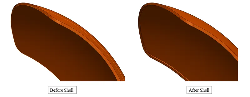
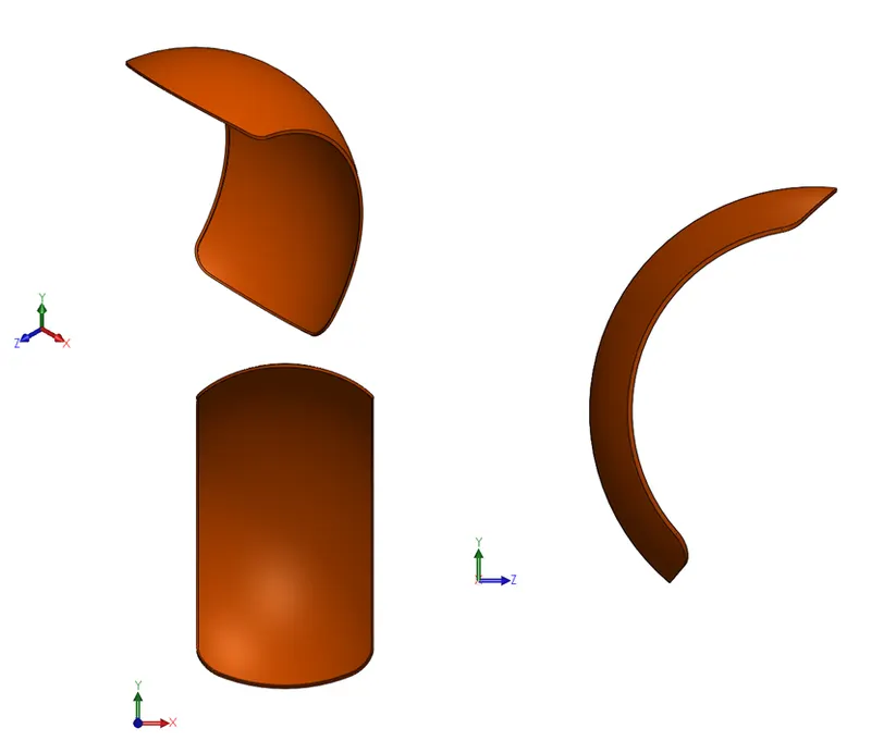
Revolve feature has been used exactly as the front fender. The profile has been created with the help of a 3-point arc. During revolve feature, the 2 different directions are used and the angle is specified to create the revolve till that particular point. Other than all these tools and features the smart dimension, spline, split and fillet.
Views and rendered images are displayed below.
· Pedal 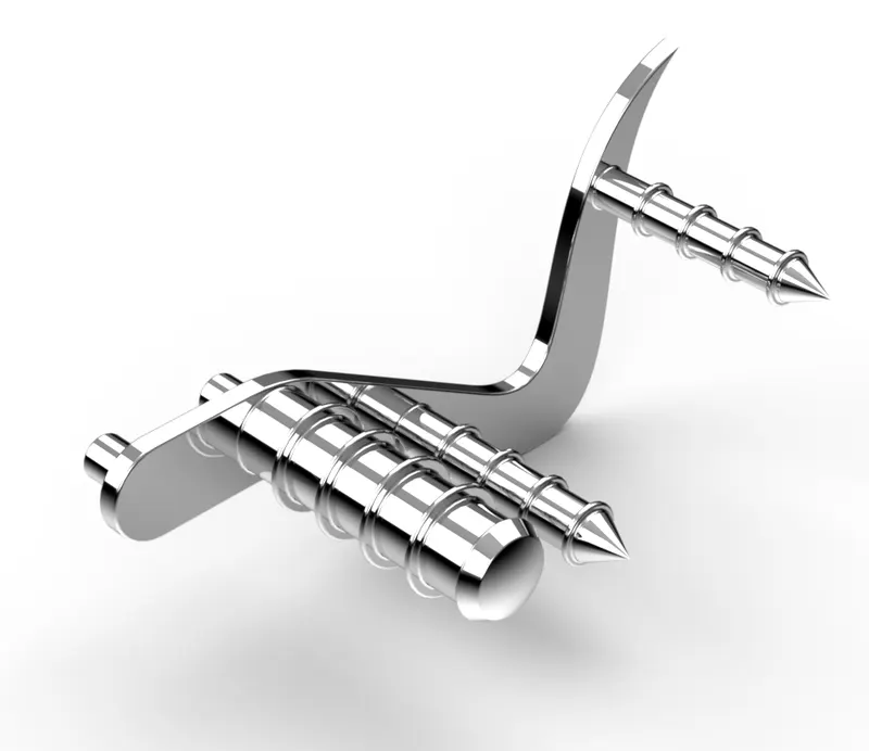
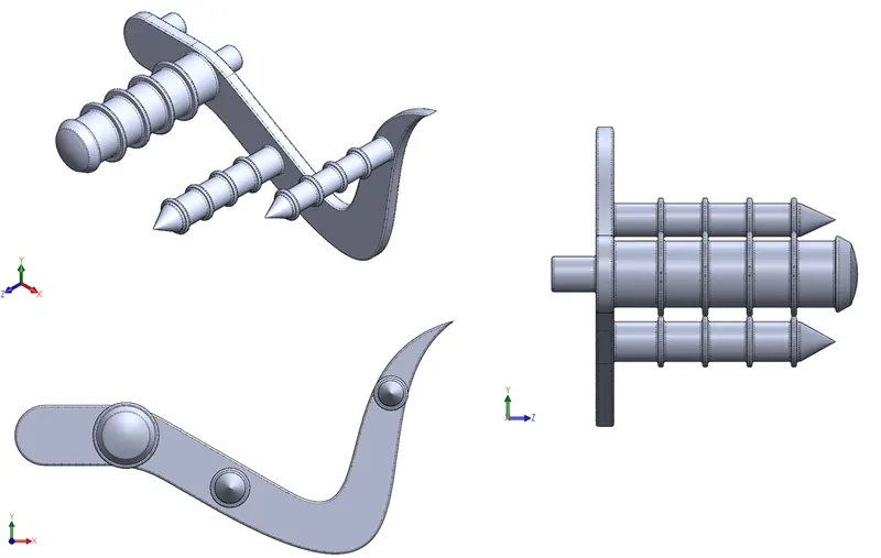
Pedal is a very crucial component for the rider as it gives the rider a lot of control over the chopper. Pedal is generally used for shifting gears by changing the gear ratio. Also used as a footrest during the rest of the journey.
Linear Pattern : Creates a pattern of any sketch, feature, faces and bodies in any linear direction. The number of instances can be specified and the distance between two consecutive entities can also be defined.
The manipulation of spline handles can be done by activating the handle of the splines. After activating the handles can be given an angle dimension and the weight can be specified in order to achieve the desired curve.
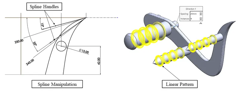
Circle : Creates a circle
Distance - Distance Chamfer  : Creates a flat face along any particular edge by specifying the distance that needs to be flattened on both the adjacent faces.
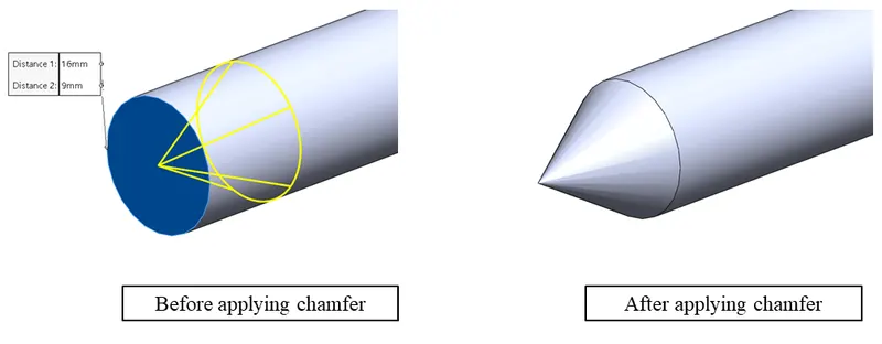
Other than the mentioned tools and features lines, revolve, dome, boss extrude, fillet and spline has been used.
Views and rendered images are displayed below
· Oil Tank 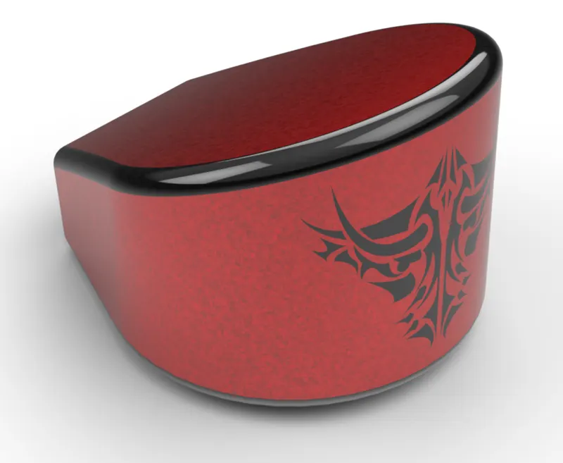
Any moving machinery requires lubrication to run smoothly and to reduce the wear and tear caused due to friction between moving parts. The oil tank acts as a reservoir for lubrication oil. Depending on the system requires the oil tank is provided with a pump to circulate the fluid in the whole drivetrain (engine, gearbox)
Combine : Combines two different solid bodies which are not merged. Combine feature provide 3 ways to combine: add, subtract, common.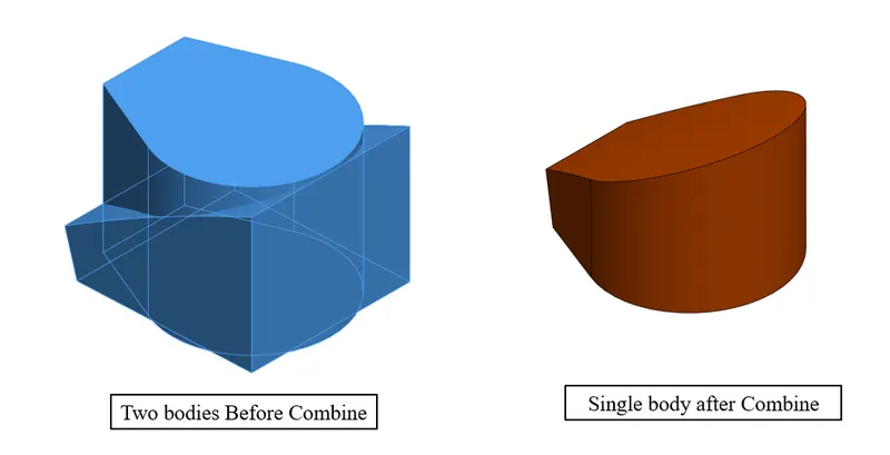
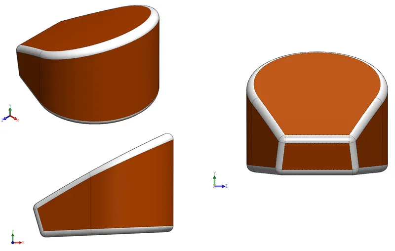
For the oil tank, a common combine feature was selected to combine the two different shaped solids resulting in a gas tank shape. The shell feature was selected without selecting any face making it hollow from inside with all sides closed. Other tools and features included: line, 3-point arc, boss extrude and fillet.
Views and rendered images are displayed below
· Chain 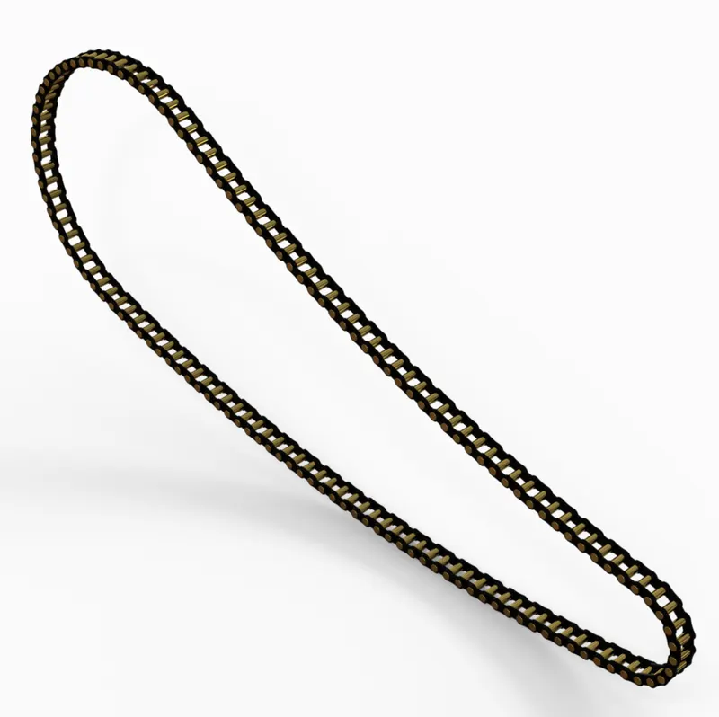
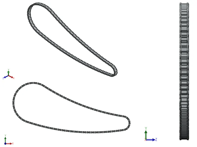
For the final drive section majority of the bike and choppers are dependent on the chain drive system. The power that is transmitted by the engine to the gearbox is further provided to the rear wheel with the help of a chain sprocket system, making it one of the crucial components of the chopper. The chain consists of chain links and pins for connecting them. The length of the chain can be adjusted by increasing or decreasing the chain links. A loose chain can cause vibrations and may create wobble, on the other hand too tight a chain can also be problematic as it causes stress on several components and can increase the rate of wear and tear on the sprocket. For this project, a roller type chain has been used.
Straight Slot  : A straight slot is created by defining the centre point of both the end arcs and the radius of those arcs.
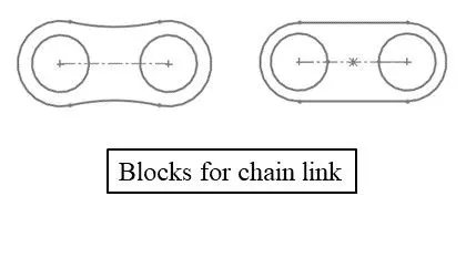
Sketch Block
 : When a particular sketch is required multiple times or is used quite often it can be saved as a sketch block making it easier to use. Anytime that particular sketch is required, the block can be imported and be worked on.
Curve Driven Pattern : Creates a pattern of bodies, faces, features along a defined curve.
Mirror : Mirrors the feature, bodies, sketches about a planar face or plane.
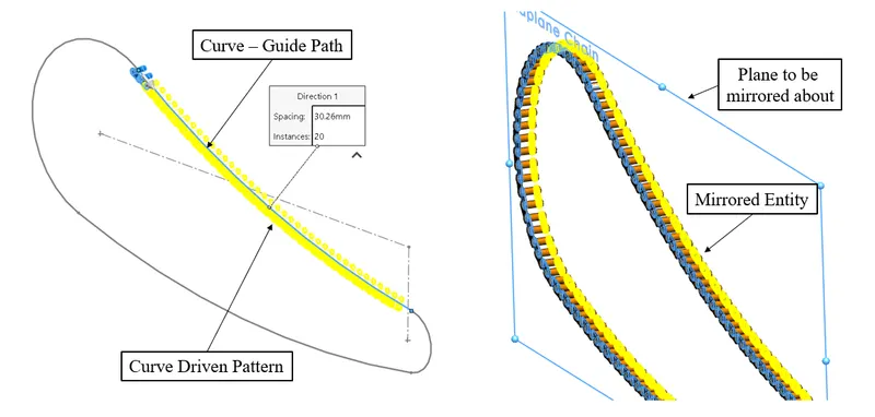
The sketch block was used quite extensively as the chain links needed to be placed perfectly. If curve driven pattern was used in the sketch, then it would have created problems every time the curve changed. To counter this issue the process was divided into segments each segment being a new curve. This helped to create almost perfect geometry. Line, circle, spline, boss extrude, and fillet were among the other tools and features used.
Views and rendered images are displayed below
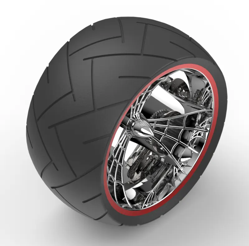
· Front Wheel 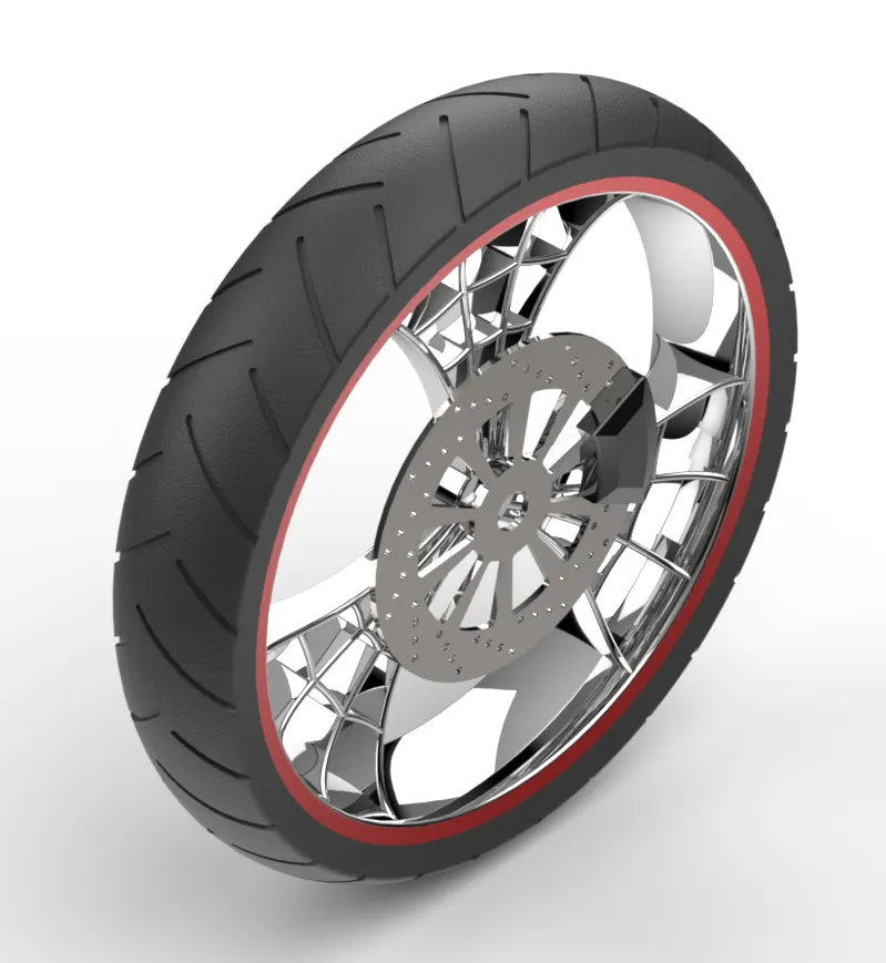
The wheel is the part where any vehicle connects to the ground making it one of the most crucial components. Design of the wheel depends on the rolling radius, the material, tire material. The tire material should be such that it creates enough traction as per the engine, otherwise may result in the spinning of the tires. Usually, softer tire materials provide better grip but at the cost of tire wear. The treads allow easy passage for any fluids under the tire to move out of the path, hence creating more footprint for the tire to grip on. The front tire is also subject to different loads as the steering turns the direction every now and then.
Circular Pattern : Circular pattern creates a pattern of anybody, face, feature along a defined circular path.
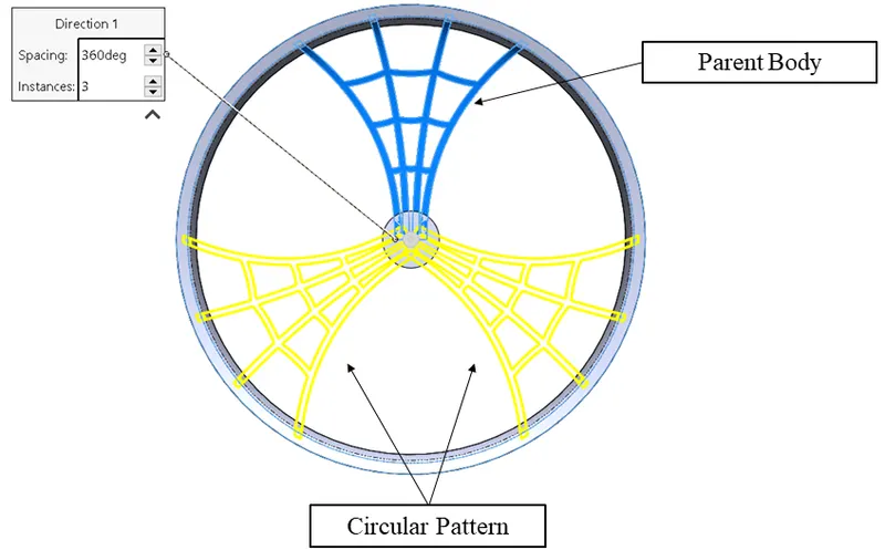
The wheel modelling goes through a lot of extruding and cut features to get the desired profile. In order to make the process simpler, the option of merging the bodies was often skipped in order to gain much more control over the modelling and was later combined. The calliper and rotor have also been modelled in the same file. Tools and features used: line, arc, trim, extend, boss, extrude, extrude cut, combine. Chamfer.
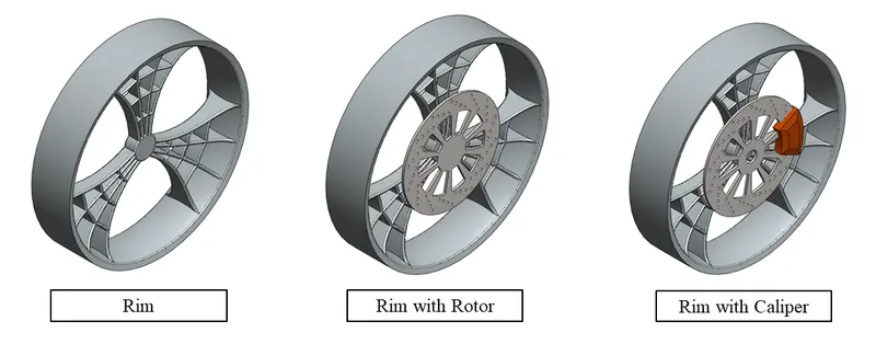
Views and rendered images are displayed below
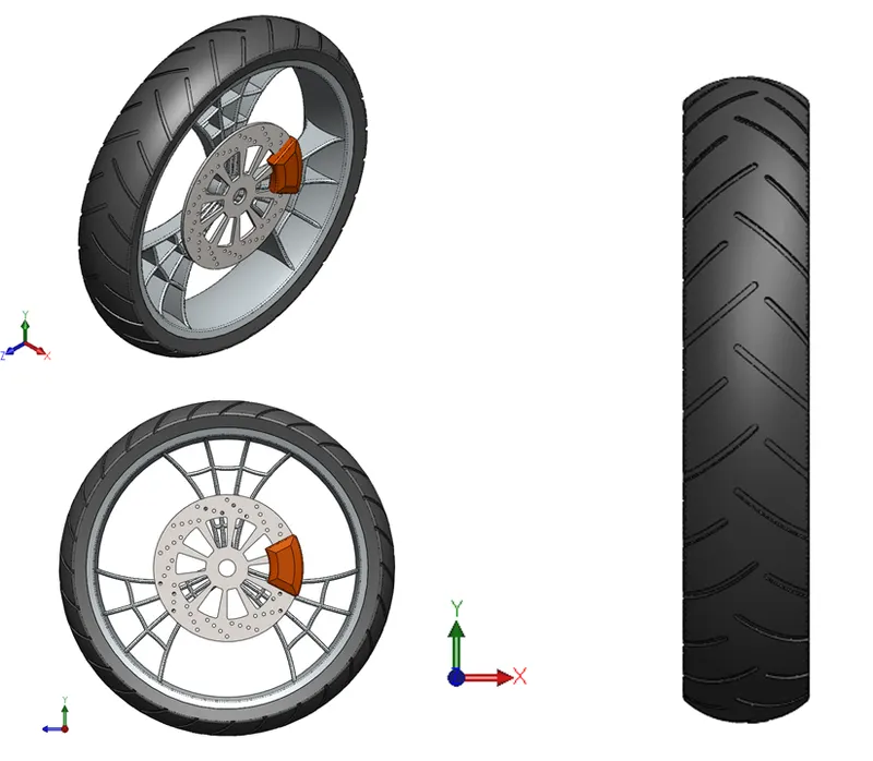
· Rear Wheel
The real wheel also requires the same factors for design as the front wheel. The rear wheel is usually connected to the final drive system (in this case chain). In addition to the calliper and rotor assembly as the front wheel, it also has a sprocket that meshes with the final chain drive. Since the power is transmitted to this wheel, the wheel is much wider than the front wheel in order to provide a much wider footprint to increase the grip. Also, it gives an aesthetic low stance to the chopper making it look much closer to the ground.
The design process of the front wheel and rear wheel are relatively the same. It changes a bit as the sprocket solid body comes into play while designing the rear wheel. The tools and features are the same as the front wheel.
Revolve Cut : Revolve cut removes the material about an axis for any particularly defined sketch entity.
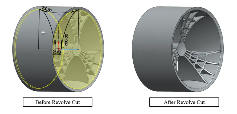
Views and rendered images are displayed below
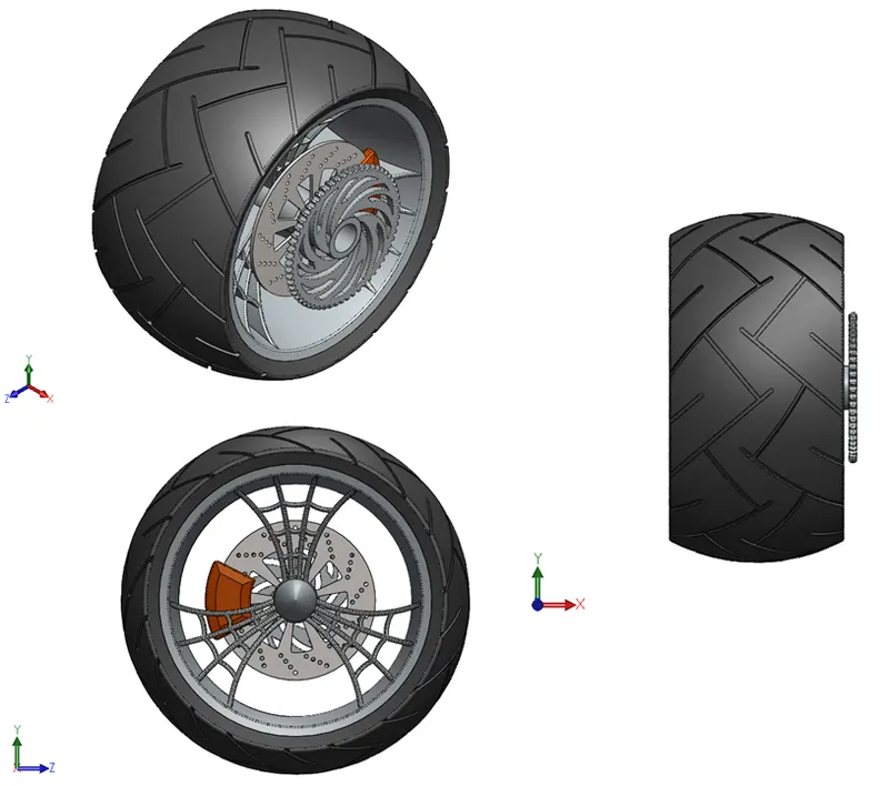
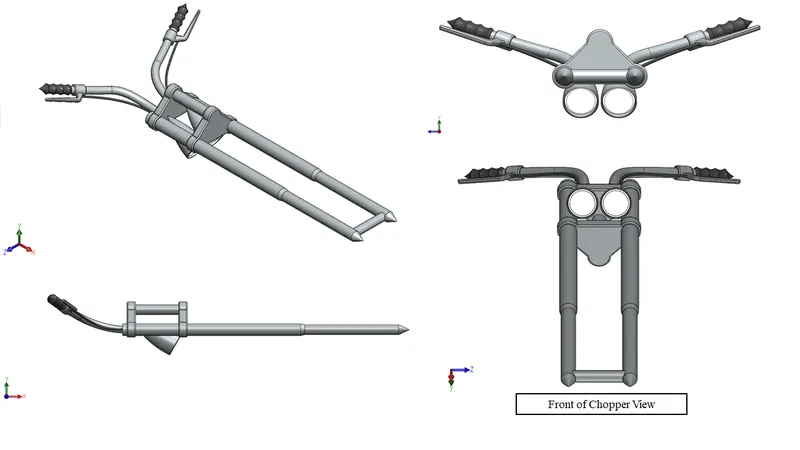
· Front Fork 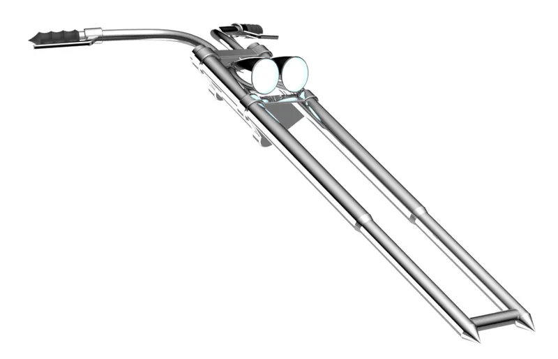
Front fork encompasses the handlebars for turning the direction of the front wheel, light bucket. In the case of a chopper, it is very long which aids in aesthetics as well.
Reference Plane : When the sketch requires some different plane that does not fall under the category of top, mid and front plane then a new reference plane is generated by applying some constraints in order to achieve the desired plane.
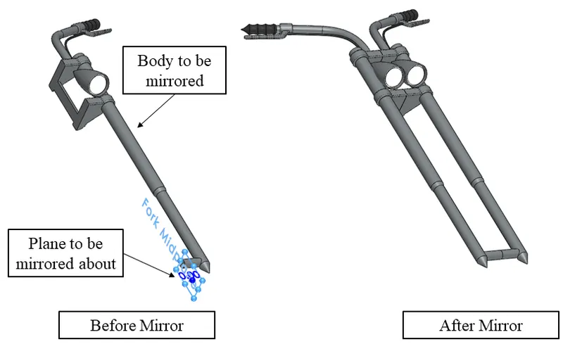
Move/Copy : When dealing with multiple solid bodies move/copy feature comes into action to tweak the design as desired. It can move, copy and rotate any slid body in any direction.
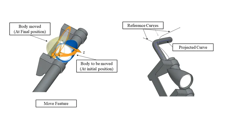
Project Curve : When dealing with complex geometry which requires the curve to travel in almost 3D space then project curves come into action. Two curves are drawn in two different planes and then a curve is projected with the help of those two curves. To make it easy to understand the individual curve can have a surface attached to them, and the intersection of those two surfaces makes the projected curve.
The light bucket is made on a conventional plane and then moved along in order to fit it in the right place. This saves the user from creating another plane and makes modelling much easier. Handlebars and the brake lines involve complex geometry which involves the curves to travel in XYZ coordinates. In order to achieve it, two different curves are used in separate planes and a projected curve is generated. Mirror, line, spline, arc, circle, revolved extrude, extrude boss are among the other tools and features used.
Views and rendered images are displayed below
· Chassis 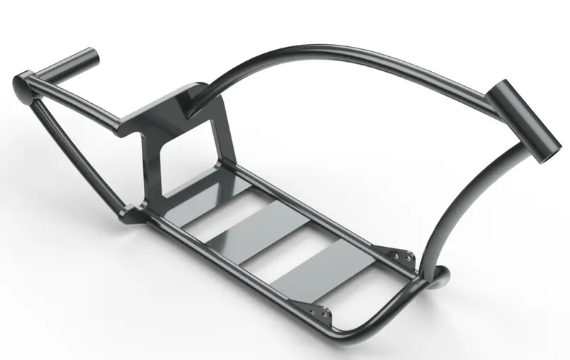
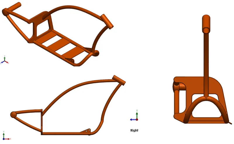
Chassis is the component where all the parts of the vehicle are placed on. It usually provides the framework for all the components that need to be on board a vehicle/chopper. Bikes and choppers most often use the tube frame chassis.
Sweep Boss Extrude : Any given closed profile is swept along an open or closed path resulting in creating a solid body.
The bottom part of the chassis has been made with the help of a projected curve in order to lift the front end of the chassis. The split part was utilized to cut the sections of the pipe which were coinciding with each other. One half of the chassis was made and the mirror feature was complete the chassis. Just the rear axle part was not includ3ed in the mirror. Line, spline, arc, curve, split, fillet, dome, boss extrude, revolve were the other features and tools used.
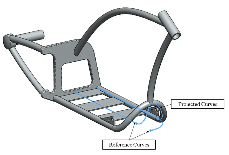
Views and rendered images are displayed below
· Engine 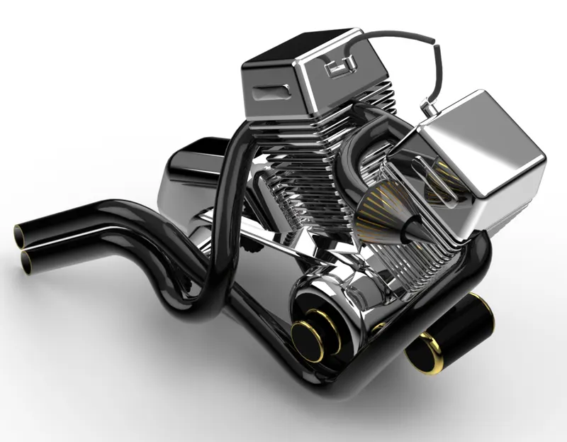
The engine is the main source of power making it a powerhouse for the chopper. It transmits the power to the gear box with the help of a transmission belt which further powers the tire with the help of a chain. In choppers and bikes, the engine is one of the biggest components that need to be carefully placed. The placement plays a crucial role as it can imbalance the chopper if placed wrongly. Also, the engine becomes hot when the chopper is operational, so the cooling system needs to be in a place where it isn’t obstructed by anything. Bike and chopper engines usually use an air cooling system so if there is any obstruction in the air path, it can lead to overheating and resulting in engine failure. The exhaust needs to be carefully paved and snuck around the engine as it is hot can harm the rider if it is protruding outside and also the pollutant gases might be in direct contact with the rider. The engine in the project is just a dummy model engine just for the representation purpose and is not functional.
Composite Curves : When two or more curves need to be joined together in order to make one complete curve then composite curves are used. These curves can be projected curves or independent curves. Makes handling complex geometry a simple task.
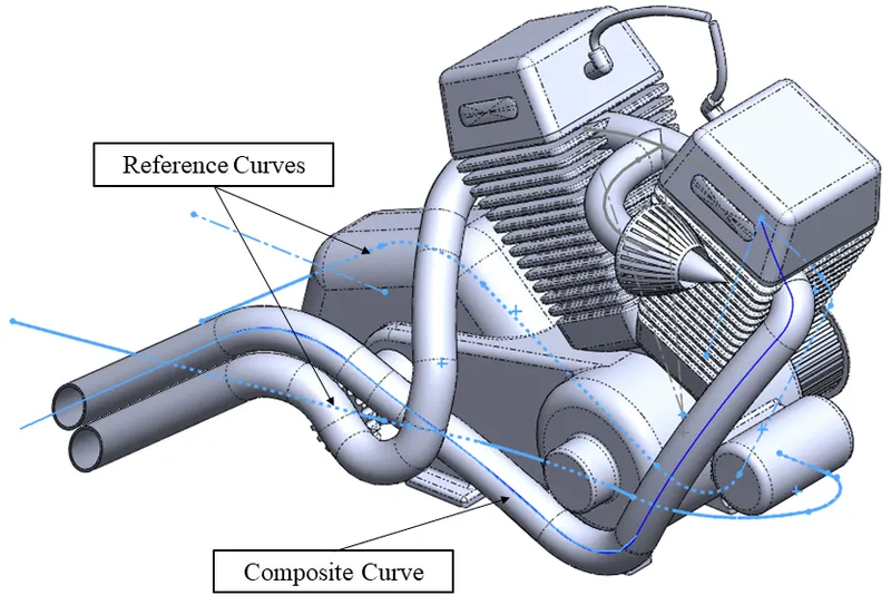
Pierce : Used for creating relations between different sketch entities when working on different planes 3D space. It pierces any sketch entity on a plane into a sketch entity on another plane so that a proper connection is established among the profiles. Mostly used while using sweep, boundary and loft features.
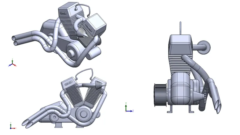
The engine had one of the most complex geometry. Initial parts like the gearbox, pulleys, cylinder heads and fins were made using normal boss extrude and extrude cut features. The complex geometry came into the picture when the exhaust system was designed. Since the exhaust system needed to be swivelled around the engine compactly, multiple curves were used to direct its path. The curves acted as a guide curve/path for the sweep feature.
Views and rendered images are displayed below
· Gastank 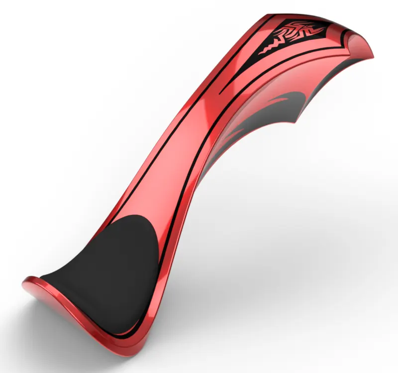
Gastank is the fuel reservoir for the chopper. It is nothing but a hollow tank just for placing the fuel and the submersible fuel pump. Since the project involves working on a chopper the gas tank is having a more designer gas tank which aids in amplifying the beauty of the chopper.
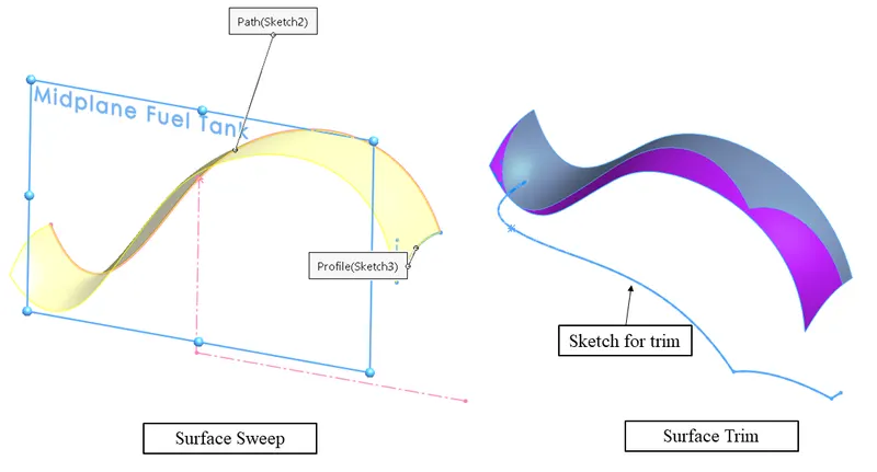
The gastank introduced the surface section and was initially modelled using the surface features and was later converted into a solid body.
Surface Sweep : It creates a swept boss along the path by moving the intended profile. It requires two curves one defining the width of the profile and other defining the length of the profile.
Surface Trim : It removes the unwanted part from the surface. User can also select the option to keep the selected part when using the feature.
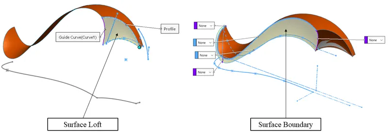
Loft Surface : A loft surface is created between two or more profiles.
Boundary Surface : It creates a surface between profiles that are having either tangent relation or are curvature continuous in all directions. The loft surface may follow a defined path and might create some geometry issues that boundary surface tends to eliminate resulting in better quality.
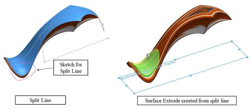
Split Line : It projects the profile or sketch entity onto any selected surface. The profile then automatically takes the shape according to the surface it is placed on.
Surface Extrude : Extrudes a sketch into a surface as per the direction. It automatically includes the edges side curves in order to create one seamless entity.
Knit Surface : Multiple surfaces are knit together into a single surface resulting in a single surface entity.
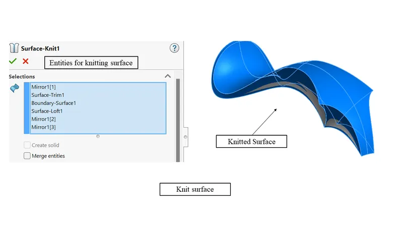
A boundary surface was also used to close the lower part of the gas tank. After that, all the surfaces are knitted together into one making it one complete entity. Now the knitted surface is converted into a solid body so that a profile can be cut for the part where the gas tank sits on the chassis. Shell feature was used in order to make the gas tank hollow.
Cut Sweep : It is just like cut extrude, just it can remove the material along a curve. It requires two sketches. One being the profile to be removed and the other being the path for it.
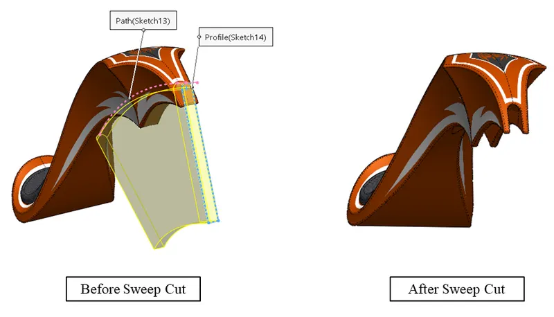
Views and rendered images are displayed below
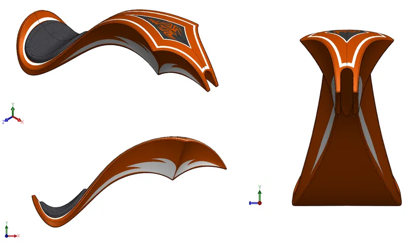
Assembly 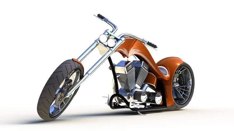
The assembly involves the mating of all the designed part models to one complete unit. This project also aims to make sure that the user learns to use the assembly feature. SolidWorks® can help the user to create full prototypes by making assemblies. These prototypes can both be working and non-working. SolidWorks® assembly offers a variety of mates that can help the user in applying normal static mates to advance mates which can help the user to create the prototype as intended.
Mate : It creates a geometric relationship between the components to define their direction and motion.
Coincident : Coincident relation was used to align planes of different parts to a single plane to have a single point of reference. All the planes were made coincident with the chassis mid plane to achieve a center alignment for all the parts.
Distance : Some parts were aligned by defining a distance between them. This can be done by defining the distance between different planes, or faces.
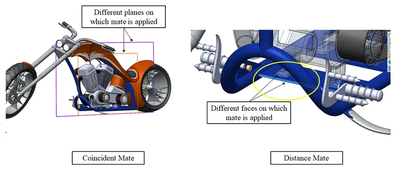
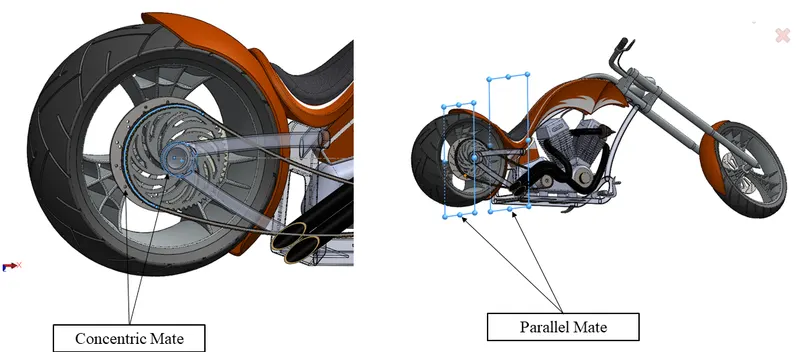
Concentric : The circular objects can be perfectly aligned by making the circles of different parts coincident with them. This can also work as a pivot point by defining the limit angle at which the part can travel.
Parallel : The parts can also be aligned by giving a parallel relation which will ensure that the two bodies never intersect each other and also a linear path can be defined for the travel.
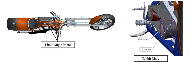
Width : When there is a gap between any two planar faces and a different solid body need to be placed between them width tool can be used. It centres one part within another. This also helps eliminate the distance issues that sometimes create trouble while applying distance mate.
Limit Angle : It limits the mate to just between a particular specified angle. Initial and the final limit is specified which act as the starting point and the endpoint for the limit angle.
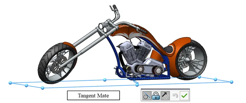
Tangent : The tangent relation comes very handy when dealing with a planar surface and a circular surface. In order to make them aligned to each other without intersecting at any point then tangent relation works wonders. In this case, the tangent relation was also used to make the chopper grounded.
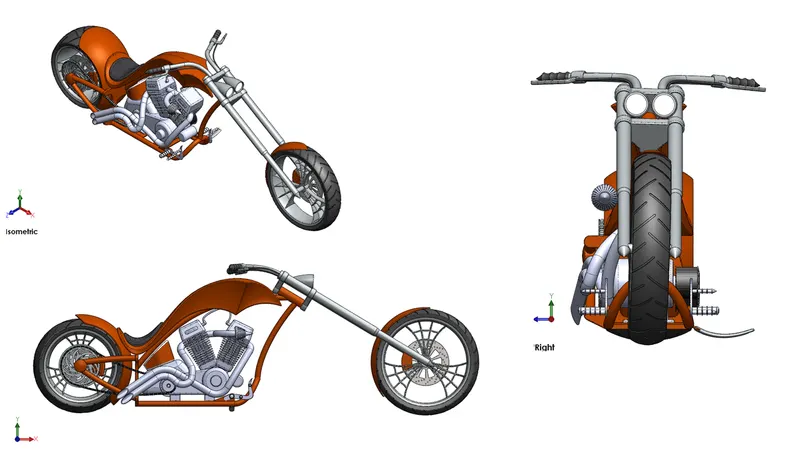
Views are displayed below
Rendering 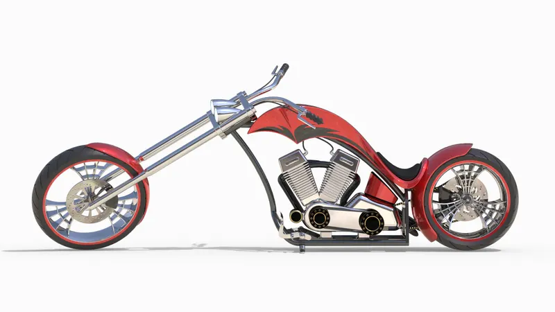
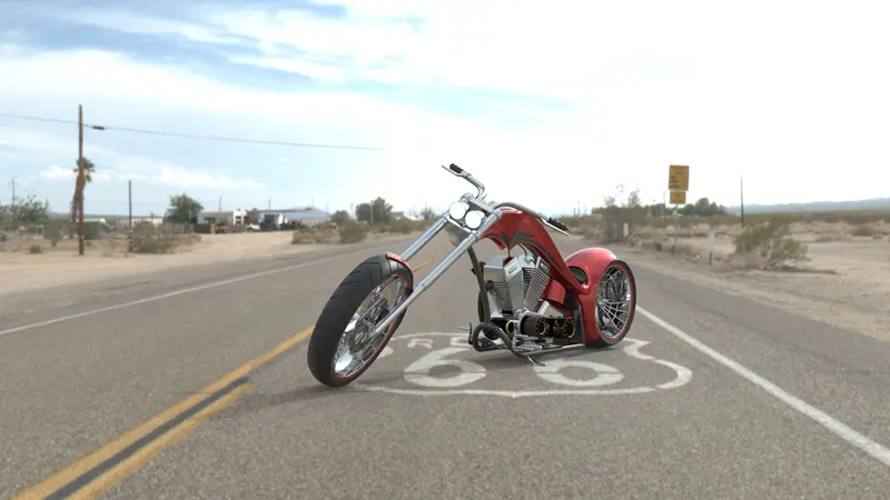
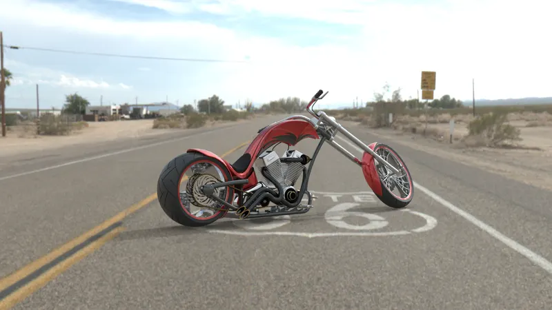
The term rendering refers to the process of creating a photorealistic image from a 3D model by undergoing a computer program. SolidWorks® offers the user to present their designed products in a photorealistic manner to the world. This allows the product to be seen in the final form. It has been a lot of help for all the engineers and designers as the product can be seen in the final form instead of spending a lot of money to make real prototypes. SolidWorks® offers to render the product in various ways. This report will be explaining only for two of them one being SolidWorks® Photoview 360 which is an add-in to SolidWorks® and the other being SolidWorks® Visualize which is a standalone software just for rendering purposes. SolidWorks® Visualize however offers much more depth in rendering and offers much more realism to the rendered photo. For this report, all the renders have been done on SolidWorks® Visualize.
Modifications have been done in almost all the part files for the rendering section in order to create a photorealistic model. For ease of understanding and to make the model clutter-free, separate display states by the name of ‘For Render’ have been created in all part file. This gives the user much more control over the part and assembly file, giving the power to make the render photo-realistic and at the same time can also be viewed in plain sight while working on the CAD file.
All the parts have been provided with a suitable appearance to make the model more realistic.
SolidWorks® Photoview 360
SolidWorks® Photoview 360 offers rendering of solid bodies in photo-like quality. It's an add-in feature in SolidWorks®. It offers to apply decals, setup camera, background, appearance, scene and lighting options.
Appearance : The appearance feature allows to apply any appearance of choice to any face, feature, solid body or the whole part. The customization can be done in a number of ways. The appearance can be in form of paints which can further be tuned as per any colour or any material like finish which can also be given any colour. SolidWorks® Photoview 360 allows a variety of options to tweak the appearance.
Scenes : Scenes are a great way to showcase the products in a real environment. How the product would look in a particular environment can be managed by scenes. Scenes also provide natural lighting and the reflections caused due to it giving it a much more realistic look.
Lighting
 : The way the user wants the light to fall on the product can be done easily with the lighting section. User can place a lighting source and also tweak the amount of light that would be omitted from that particular source. The reflectivity of the scene can also be adjusted from the lighting section.
Decals : Any 2D image that the user wants to be displayed on the model can be done with decals. The decals can be placed on the model in numerous ways. The image can be manipulated by applying a mask, selecting the alpha channel. Products that require instructions for use, general warning signs can have them placed on the product in form of decals.
Camera : Adjusts the position from which the render needs to be done or the chopper needs to be viewed. There are different perspective settings, different cameras lens, rotation also the field of depth.
Options : This allows the user to adjust the render quality and the size of the image.
SolidWorks® Visualize 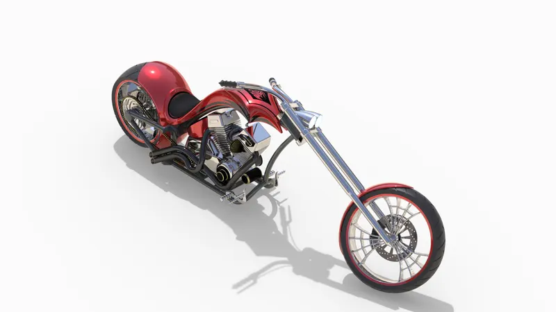
SolidWorks® Visualize is a standalone software made just for rendering. It offers much more features to render any model and the image output is also much better than SolidWorks® Photoview 360. Not only SolidWorks® CAD files but CAD files from other software can also be imported to create renders. The renders can also be done on different computers by using a network offered by the Boost service.
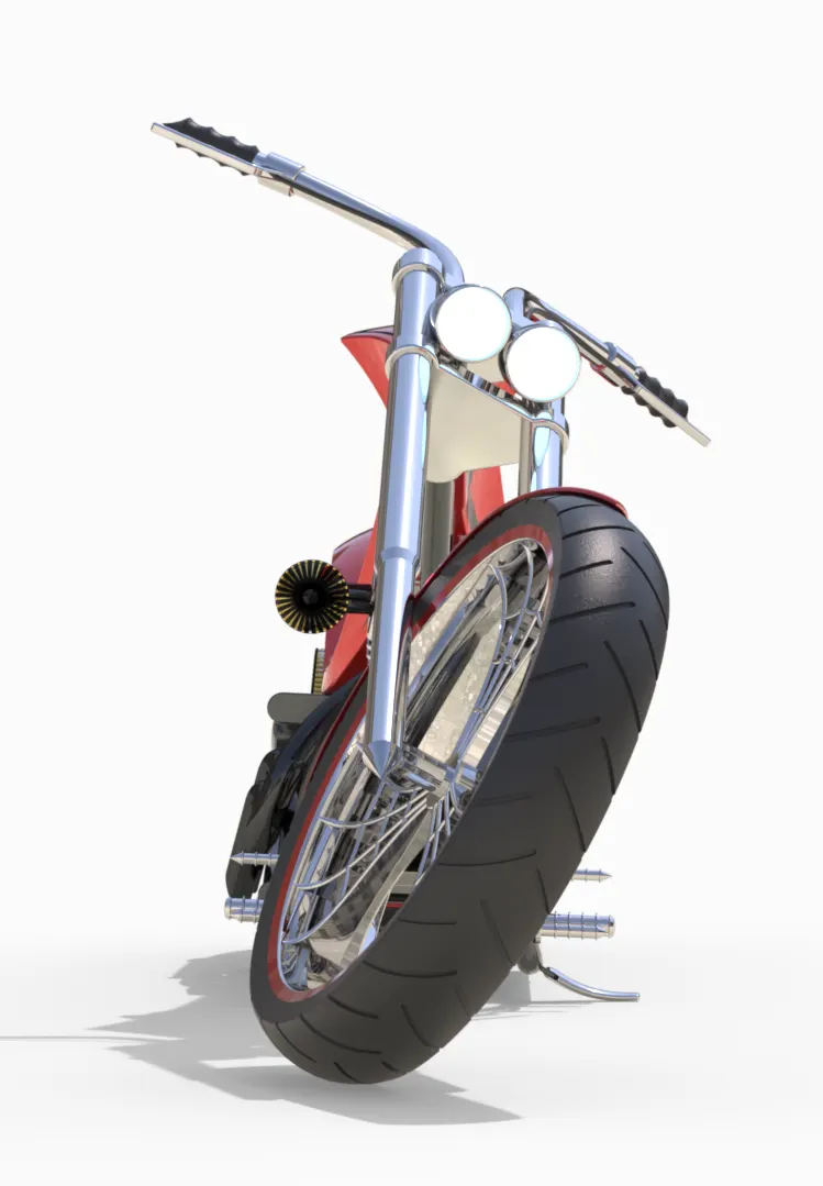
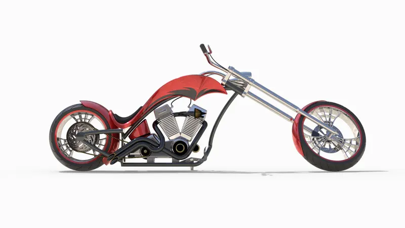
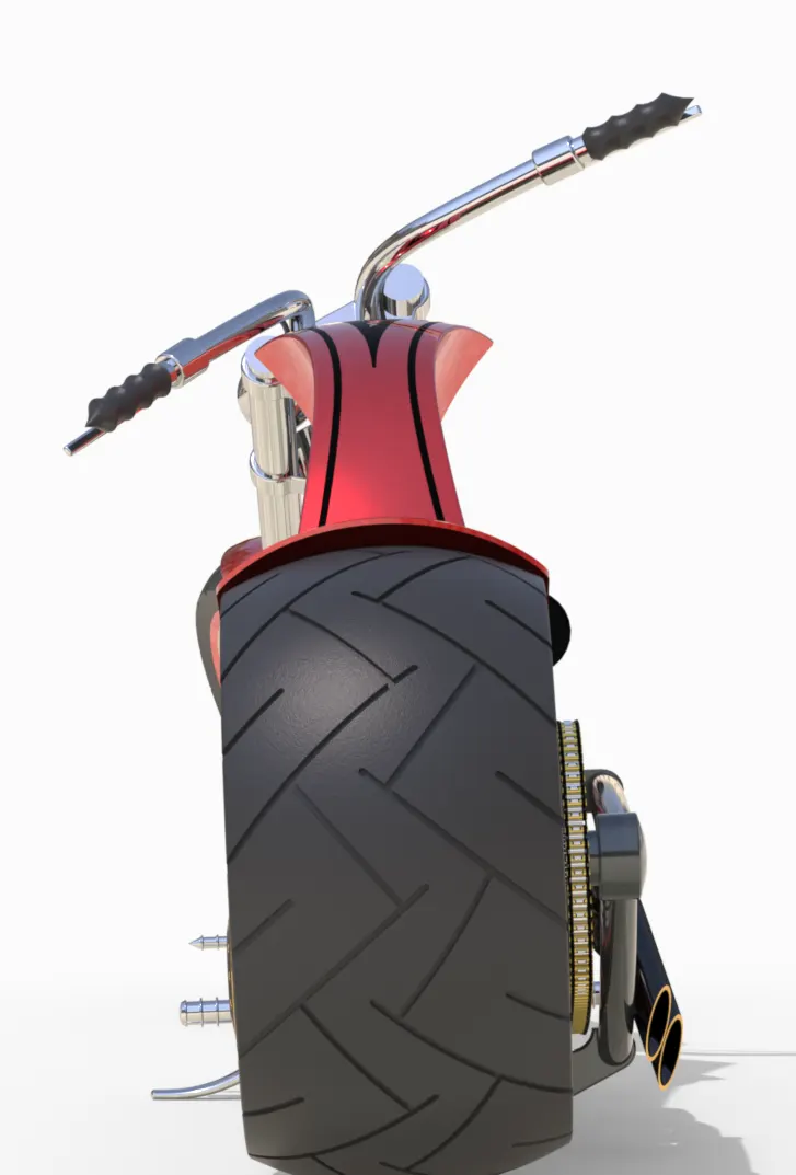
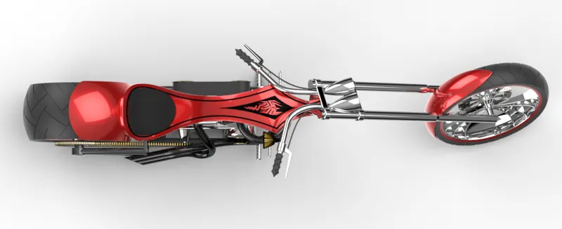
Camera Setup View with Route 66 HDRi environment. No backplates were used.
Conclusion
- All the tools and features required to do part modelling were learnt thoroughly while modelling all the parts.
- Assembly feature was clear by using all types of mates and constraints that are needed to create a completely error-free model.
- Showcasing the chopper in a photorealistic manner was made possible by learning all the features and tools offered by SolidWorks® Photoview 360 and SolidWorks® Visualize
- This particular project has enabled to design of an American Chopper right from sketch to a photorealistic quality model.