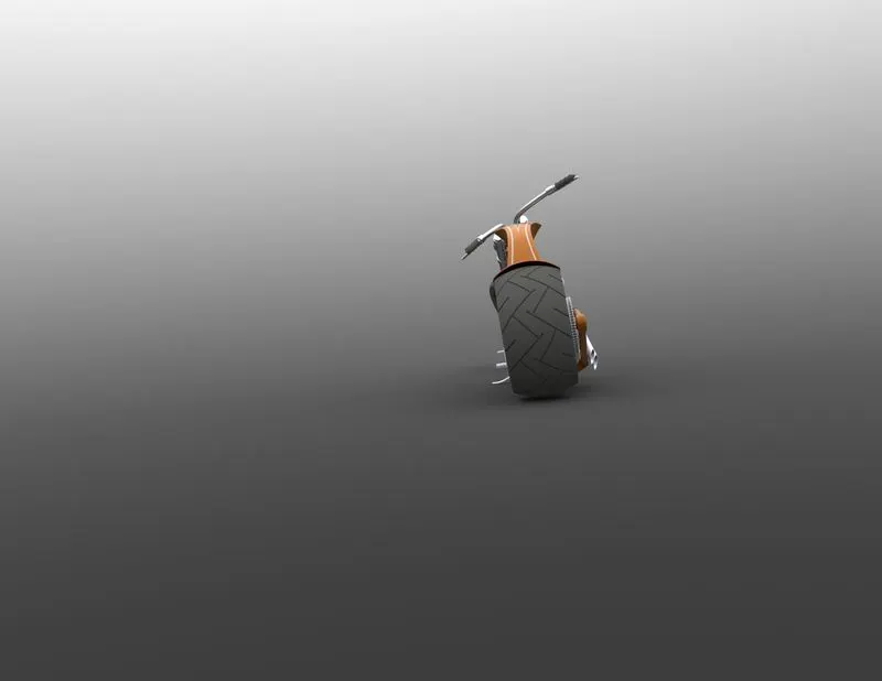
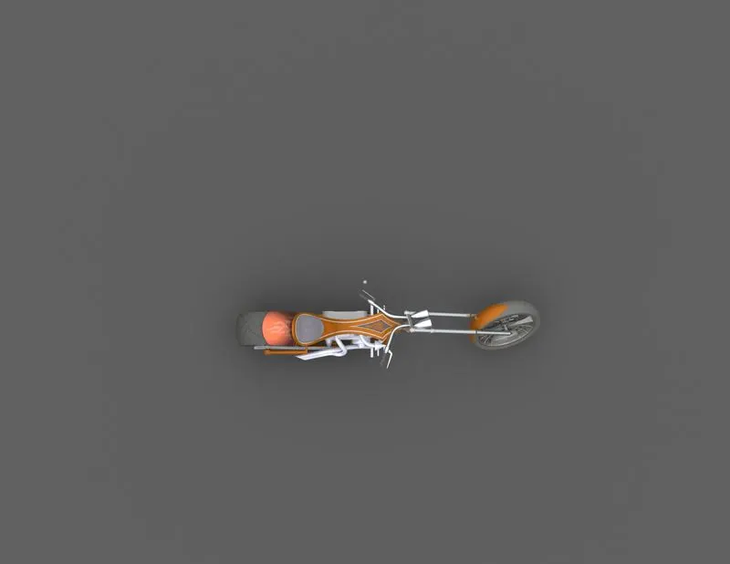
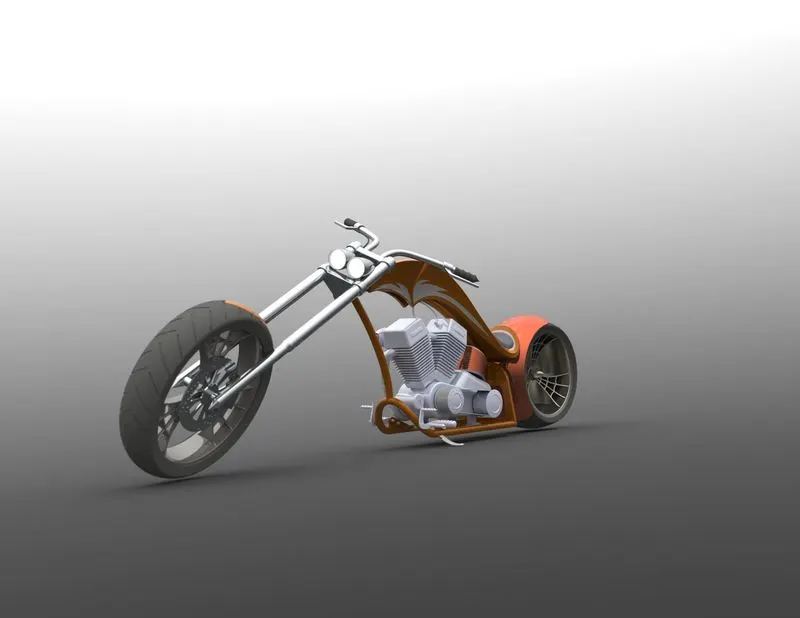
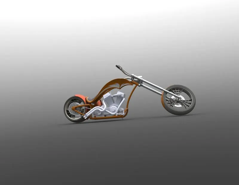
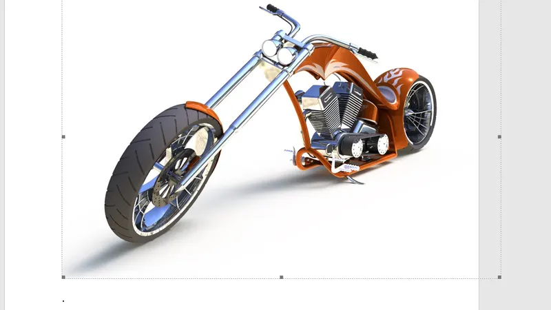
Photo Realistic Rendering
- MODELING OF AMERICAN CHOPPER OF SOLIDWORKS
GODWIN PRABHU.
Introduction
A chopper is a type of custom motorcycle. The chopper is perhaps the most extreme of all custom styles, often using radically modified steering angles and lengthened forks for a stretched-out appearance. Some of the characteristic features of choppers are long front ends with extended forks often coupled with an increased rake angle, hardtail frames very tall "ape hanger" or very short "drag" handlebars, lengthened or stretched frames, and larger than stock front wheels.
The first choppers were built in America and tended to be based on Harley-Davidson motorcycles.
So the purpose of this project is to create an aesthetic model of a chopper using Solidworks and Solidworks Visualize.
Objectives
- To design and model the exterior parts of an American Chopper(motorcycle).
- To assemble the parts.
3. To create a photorealistic render of the Chopper
- Extrude boss
- Fillet
- Revolve boss feature
- Extrude cut
- Shell
- Linear pattern
- Mirror
- Reference geometry
- Projected curve
- Knit
- Mate
Extrude Boss
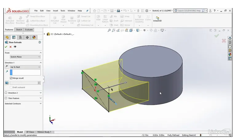
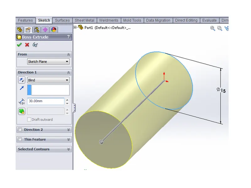
In this blog we will be covering the Extruded Boss/Base feature, this is one of the most common and universal features used within the 3D modeling world. This is a handy feature for creating 3D solid models within SolidWorks.
Using the modeled 2D sketch created (see Creating Sketches a how to blog), you are ready to turn the 2D sketch element into a 3D solid feature. The Extruded Boss/Base feature can be found on the features tab in the Command Manager interface
Fillet
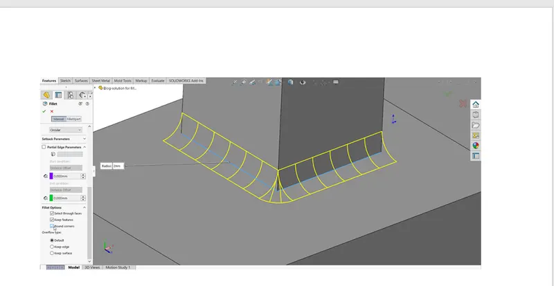
When we draw a solid part it is having some sharp edges. To give the roundness to those edges we add fillets. It makes the sharp edges or corners round shape of having different sizes or radius. The material can be added or removed according to conditions whether edges are internal or external. Fillets are used to solid bodies to hide the corners and edges and also it gives nice appearance to the part. Various types of fillets are used according to the given condition or it depends upon the part.
Revolve boss feature
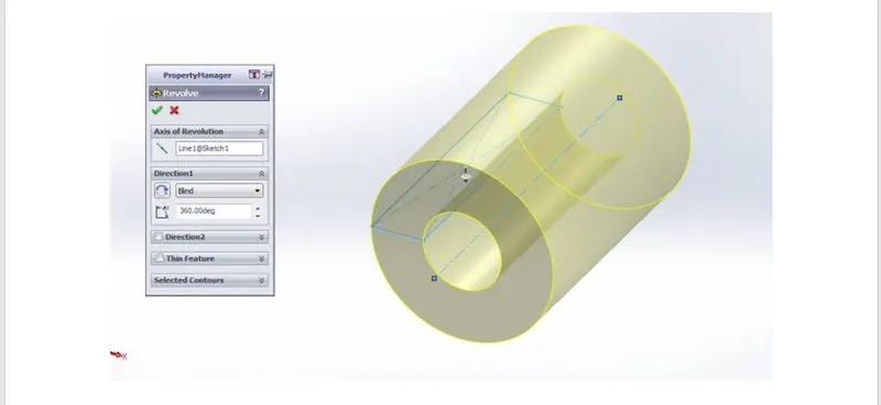
This feature works around an axis, by selecting axis of a sketch it adds a round material by revolving around that axis. If there is no axis we can select an edge of a sketch and it gives us appropriate geometry
Extrude cut
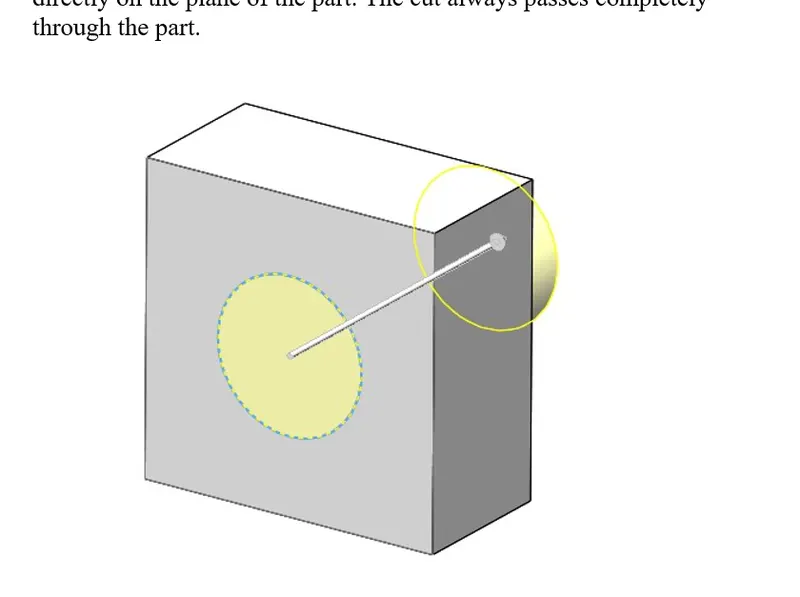
You create an extruded cut in a two-dimensional or axisymmetric planar part by sketching the two-dimensional cross-section of the cut directly on the plane of the part. The cut always passes completely through the part.
Shell
It is very handy tool in SOLIDWORKS. It gives some sort of idea that how inside geometry of a part will appear. In this tool we give inside thickness to the geometry and material removed from the body and it becomes hollow.
Linear pattern
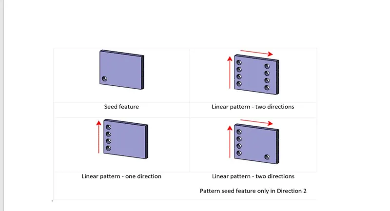
Use linear patterns to create multiple instances of one or more features that you can space uniformly along one or two linear paths. ... To create a linear pattern: Create one or more features to replicate. Click Linear Pattern (Features toolbar) or Insert > Pattern/Mirror > Linear Pattern.
Mirror
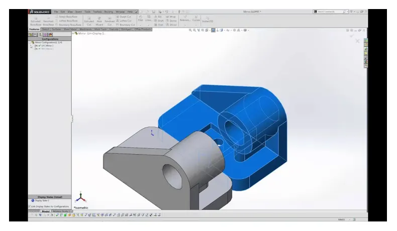
The mirror entities feature can be found under the ‘sketch’ tab in the command manager or in tools > sketch tools > mirror. When selected the mirror feature will ask you to pick the entities you want to mirror (in this example the blue entities), the line of symmetry you want to mirror about (the construction lines), and whether or not you want the mirror to copy or clear the original entities. Dimensions can be added before or after the mirror depending on preference.
Reference geomet
It defines the shape or form of a surface or a solid. This includes features such as planes, axes, co-ordinate system and points. This can be used according to need in a sketch.
Use of reference geometry example:
- Axis: If we want to pattern something and axis is not available by using reference geometry axis it gets easier to make pattern.
- Plane: If we need to sketch and there is need of plane by using reference geometry plane we can draw it and complete the sketch.
Projected curve
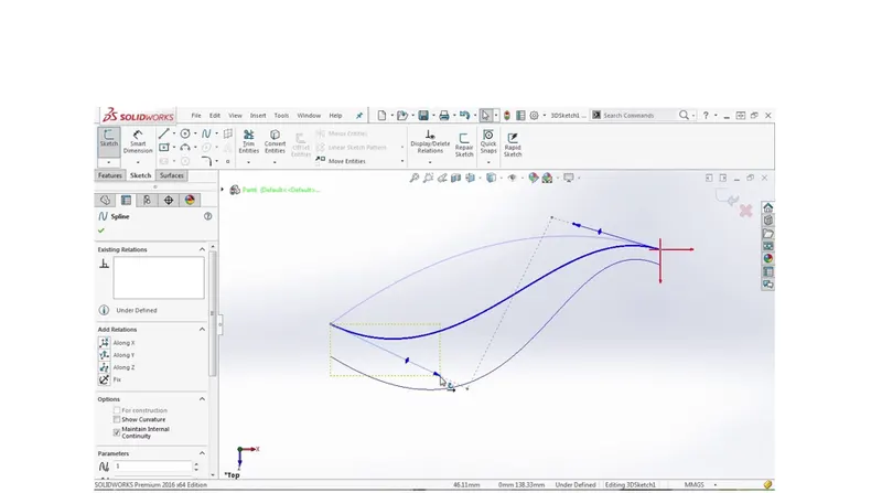
The curve can be project by a sketch into a model to create a 3D curve. We can create multiple closed or open contour projected curves from a single sketch. Generally the curve can be intersection of two extruding surfaces. The curve which is created can be use as a path for the sketch of the part. Note: It do not create curve of an intersecting curves.
Knit
Use of knit surface tool to combine two or more faces and surfaces into one. It create a solid body when the knit surfaces form a closed volume or leave as a surface body.
Mate
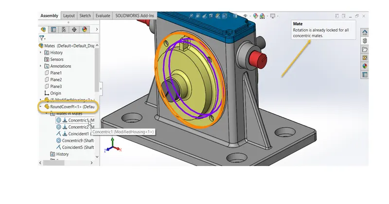
Mate creates geometric relationship between assembly and component. When we add mates, it defines the allowable direction of linear or rotational motion of component within its degree of freedom, visualizing the assembly’s behavior.
This feature includes:-
Coincident mate: Coincident mate make two planar faces to become coplanar. This mate can move along one another but cannot be separated.
- Concentric mate: This makes two circular faces to become concentric and can move along the common axis.
- Tangent: This feature can be use between a face and plane to make tangent mate.
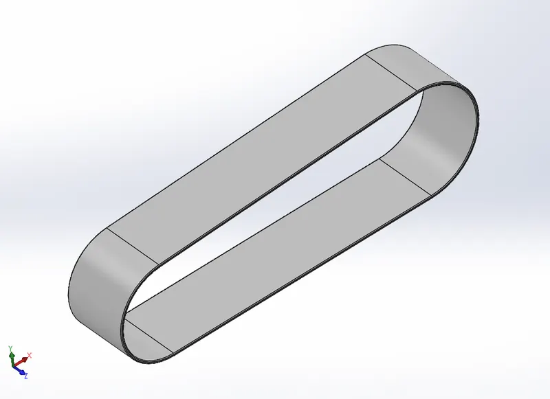
- Transmission Belt
Transmission Belt is a loop of flexible material used to link the two rotating shafts mechanically.
Commands used- Sketch, Extruded Boss, Offset Entities, Fillet
2. Kickstand
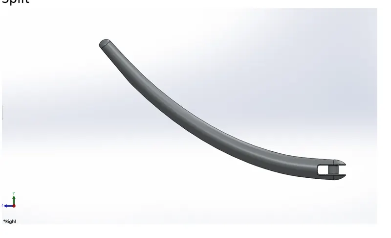
Kickstand is used to support the vehicle by keeping it upright. Commands used- Sketch, Lofted Boss, Dome, Extruded Cut, Split body, Extruded Boss, FilletSome design changes were made to the kickstand during the Assembly for getting the desired
3. Front Fender
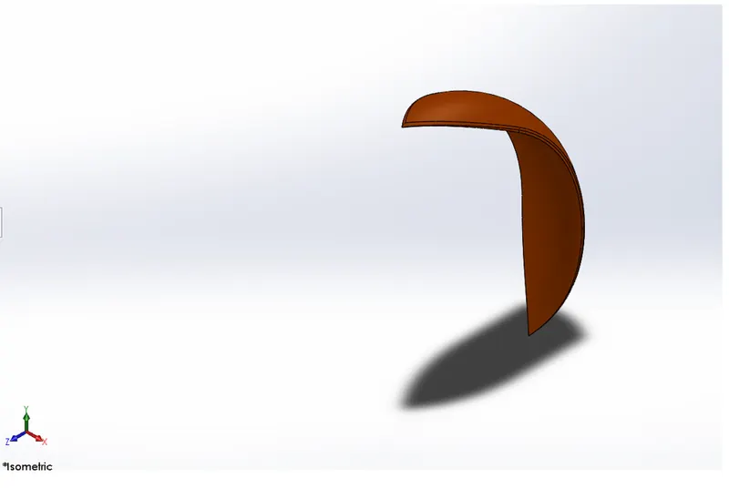
Fenderis a body that frames the wheel well. Its primary purpose is to prevent sand, mud, rocks, liquids, and other road spray from being thrown into the air by the rotating tyre.Commands used- Sketch, Offset Entities,Revolved Boss, Split body, Fillet.
4. Rear Fender
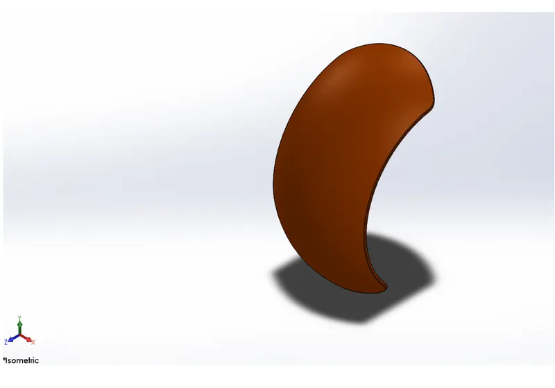
Fender is a body that frames the wheel well. Its primary purpose is to prevent sand, mud, rocks, liquids, and other road spray from being thrown into the air by the rotating tyre.
Commands used- Sketch, Offset Entities, Revolved Boss, Split body, Fillet, Shell.
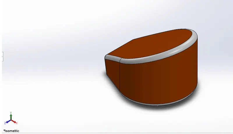
5. Oil Tank
Stores the oil for lubrication and cooling purposes.
Commands used- Sketch, Extruded Boss, Combine, Fillet, Shell (Internal).
6. Chain
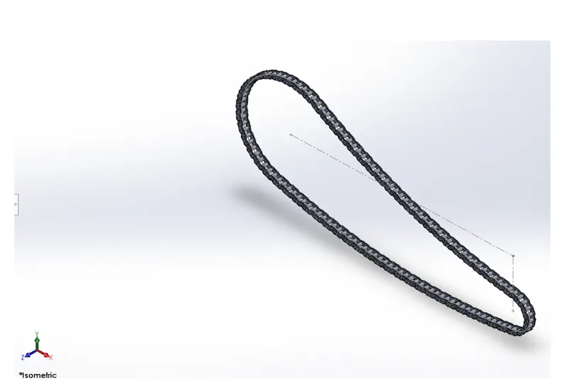
Chain drive is used for transmission of mechanical power, in this case the power from the engine to the wheels of a vehicle.
Chain drive design was a lengthy process as it required repetition of various commands. But the Curve Driven Pattern and Mirror commands in Solidworks came handy in this case.
Commands used- Sketch, Make block, Extruded Boss, Fillet, Curve Driven Pattern (repeat for each path), Mirror
7. Pedal
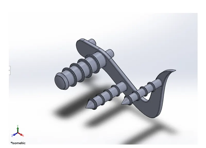
Used for placing the foot, applying brakes and shifting the gear in a motorcycle.
Commands used- Sketch, Extruded Boss, Fillet, Revolved Boss, Dome, Chamfer, Linear Pattern.
8. Front Wheel
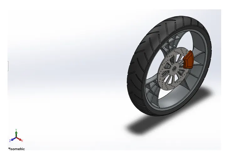
The front wheel consists of the unique spider web shaped rims, tyre, brake rotor and caliper.Commands used- Sketch, Offset Entities, Convert Entities, Trim Entities, Revolved Boss, Extruded Boss, Extruded Cut, Revolved Cut, Circular Pattern, Combine, Fillet, Chamfer.
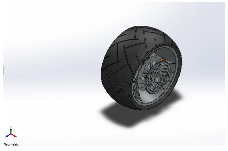
- Rear Wheel
The wider but stockier rear wheel consists of the unique spider web shaped rims, tyre, brake rotor, caliper and sprocket.
Commands used- Sketch, Offset Entities, Convert Entities, Trim Entities, Revolved Boss, Extruded Boss, Extruded Cut, Revolved Cut, Circular Pattern, Combine, Fillet, Chamfer
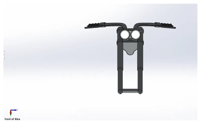
- Front Fork
The fork connects the front wheel and axle to its frame, typically via a yoke, also known as a triple clamp, which consists of an upper yoke joined to a lower yoke via a steering stem, a shaft that runs through the steering head, creating the steering axis.
Commands used- Sketch, Revolved Boss, Extruded Boss, Fillet, Linear Pattern, Extruded Cut, Dome, Revolved Cut, Move/Copy
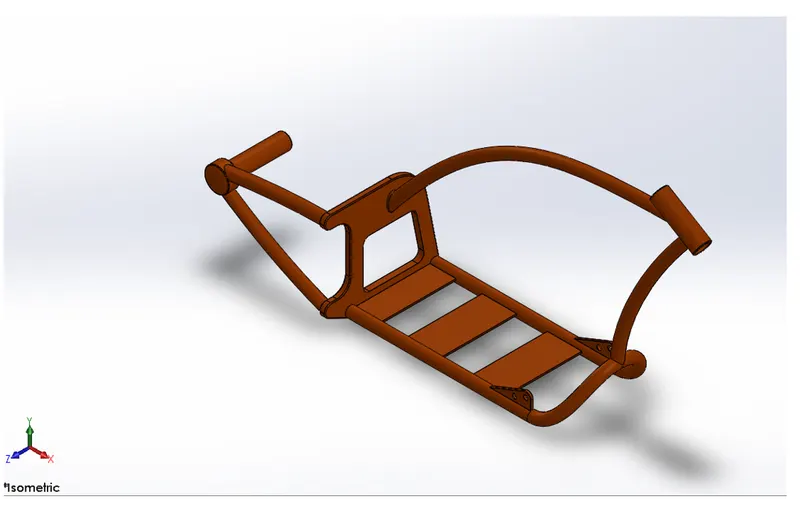
- Chassis
Chassis/frame is the motorcycle's core structure. It supports the engine, provides a location for the steering and supports the rear end and the rider along with any passenger or luggage. The fuel tank is attached to the frame.
Commands used- Sketch, Convert Entities, Project Curve, Swept Boss, Mirror, Extruded Boss, Extruded Cut, Chamfer, Fillet, Dome, Split Body,
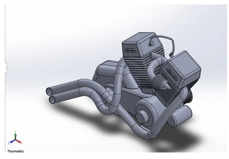
12. Engine
An engine powers a motorcycle. Here, a V-twin engine, also called a V2 engine is used. It is a two- cylinder piston engine where the cylinders share a common crankshaft and are arranged in a 'V' configuration. The Vee configuration generally reduces the overall engine length, height and weight compared with an equivalent inline configuration.
13. Gas Tank
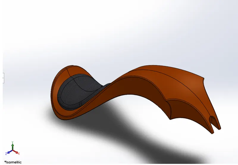
Unlike other parts where Solid Modelling was used, gas tank was majorly designed using Surface modelling, given its curvy geometry.
Commands used- Sketch, Convert Entities, Swept Surface, Trim Surface, Project Curve, Lofted Surface, Boundary Surface, Mirror, Knit Surface, Split Line, Extruded Surface, Fillet, Swept Cut, Shell.
2.Assembly
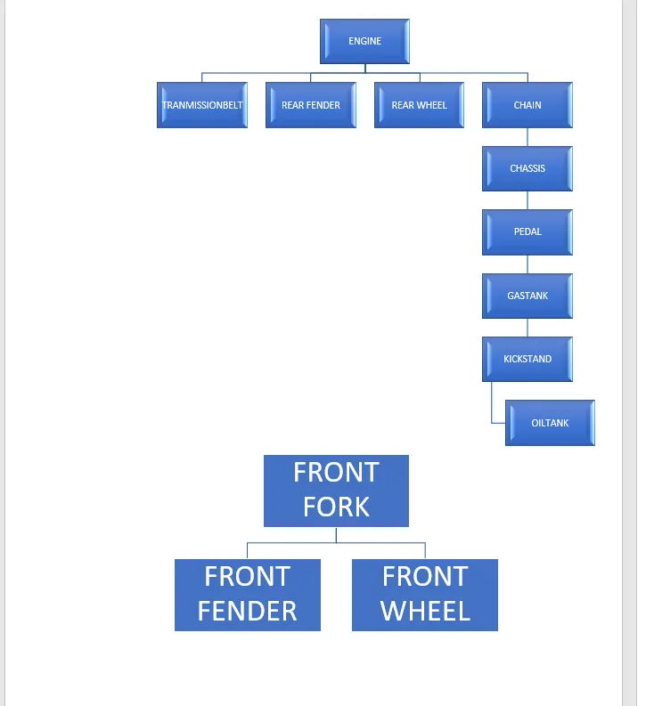
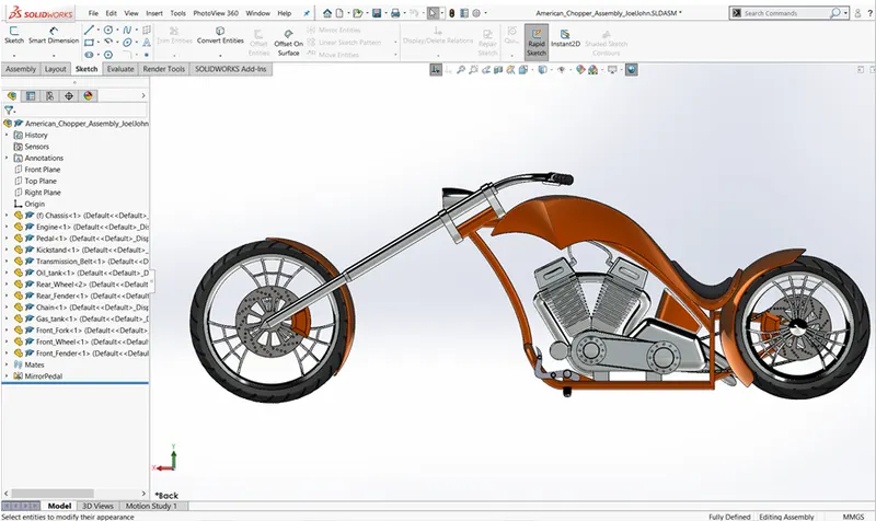
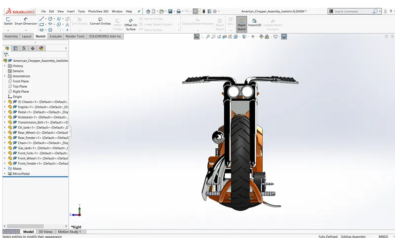
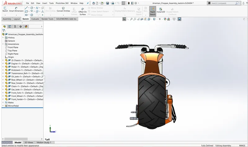
Assembled the parts of the chopper using relations, Standard Mates(Coincident, Parallel, Tangent, Perpendicular, etc) , Advanced Mates (Symmetric, Width, Angle, etc) and Mirroring.
Plane orientation/alignment was taken care of while performing the mating.
Some parts like kickstand and front fork needed a limiting angle which was set while applying mates. Some parts had to be edited to avoid any bad geometry from showing up in the assembly
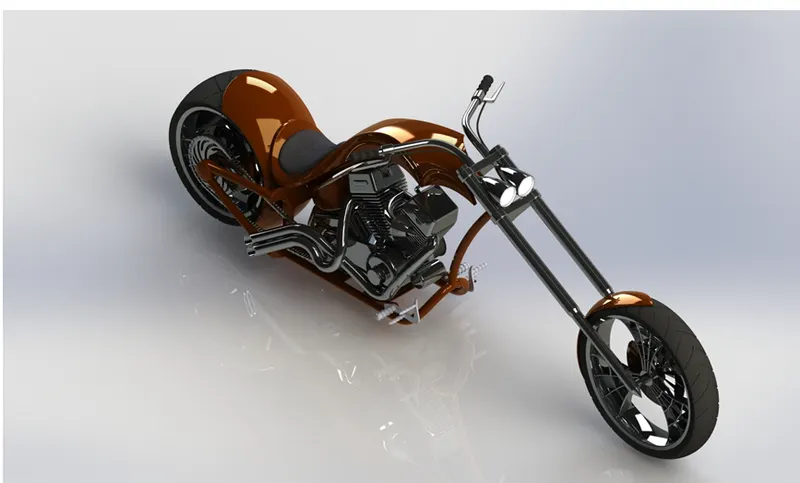
1. Photoview 360
Rendering using Photoview 360 involved setting the Scene, Environment, Camera, Perspective and Lights by adjusting various parameters. Extra mates were added to give a realistic view of the scene.
Colour adjustments were done if required.
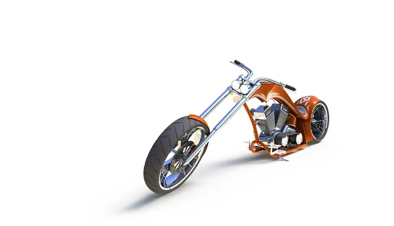
- Solidworks Visualize
The assembly was imported to Solidworks Visualize and various adjustments in colour were done in case of multiple renderings. The Environment, Backplate and Camera positions were chosen and tweaked accordingly to give the image a photorealistic finish.
Three renderings were done using different views and scenes