Photo Realistic Rendering
CHOPPER DESIGN & RENDERING
OBJECTIVE:
To design all major parts of an American chopper model and assembly every part with all constraints. Finally, Render the assembly of the chopper in different scenes and environments.
Introduction:
A Chopper is kind of modified motorcycle which has characteristic features of long front ends with extended forks often coupled with an increased rake angle, hardtail frames (frames without rear suspension), very tall "ape hanger" or very short "drag" handlebars, lengthened or stretched frames, and larger than stock front wheels.
One famous example of chopper is Harley-Davidsons chopper used in the movie Captain America.
DESIGN METHODOLOGY
PARTS DESIGN ---> COLOR AND MATERIAL ASSIGN ---> CREATE ASSEMBLY ---> IMPORT AND FIX CHASSIS FIRST ---> ONE BY ONE IMPORT OTHER PARTS DESIGNED SEPARATELY AND ASSEMBLE WITH CHASSIS ---> MAKE PEDAL MIRROR FOR OTHER SIDE AFTER GIVING CONSTRAINTS TO ONE SIDE DESIGNED SEPARATELY ---> SAVE THE ASSEMBLY FILE ---> PREPARE LIGHTING AND VIEW REQUIRED FOR CHOPPER RENDERING ---> ADD CAMERA VIEW AND ADJUST LIGHT SETTINGS ---> PREVIEW THE RENDERING OF CHOPPER ---> ADJUST RENDERING SETTING IF REQUIRED OR ELSE GIVE FINAL RENDER ---> DOWNLOAD THE RENDER IMAGE AND KEEP REPEATING FOR VARIOUS VIEWS AND BACKGROUND IF NEEDED.
DESCRIPTION
A Chopper usually consists of many mechanical and electronic parts. In this project, we have designed major mechanical parts required and rendered to project a complete good-looking chopper model with decals.
The main parts design of chopper design and rendered in this project are
- Engine w few harness wire and Exhaust
- Chassis frame
- Front-wheel w disc brake unit and fender
- Rear-wheel w disc brake unit and fender.
- Front Suspension fork w headlight unit.
- Side stand
- Fuel Tank
- Oil Tank
- Chain sprocket
- Propeller belt (Tran’s belt).
- Pedal.
Most of the design approaches are explained in each part design submission.
So I would like to explain the assembly and rendering procedure mainly below for the above parts.
Assembly Sequence
- First Chassis is imported and fixed at all constraints.
- Then the engine is fixed on the provision made in the chassis and locked in to prevent any direct movement from the chassis with coincident, distance, and concentric mate commands.
- Then kickstand is imported and locked in chassis with a limit angle mate option so that it can still move between two angles as it will in an actual vehicle.
- Then Tran’s belt is fixed to the engine with concentric, Width, and angle mate options.
- Then oil tank is placed between chassis and engine with a coincident mate option.
- Then Rear wheel is placed in the rear end of the chassis with a Concentric, coincident, and parallel mate option along with a few more mate commands to interlock the Chain sprocket with the Rear-wheel hub.
- Now Fuel tank is mounted on the chassis with distance, coincident mate option.
- The next Front fork is assembled to chassis with concentric, width, and limit angle mate option. This will enable the front fork to lock and move in the chassis as it will be in the actual vehicle.
- The next Front-wheel is assembled to the front fork with a concentric, coincident mate option.
- Finally, the Pedal is assembled to the chassis with a coincident, concentric mate option. The other side of the pedal is mirrored to keep on both sides of the chassis.
RENDERING SEQUENCE
- After all, parts are assembled in the chassis, the chopper is ready for rendering. Switch on photo view 360 render tools to start rendering the chopper.
- First, assign of material of each component if not assigned in each part.
- Then we prepare the screen and view required for the chopper. We tilt and set the view of the chopper and save it a new camera view. Then we add a camera and adjust its location until the image is positioned properly on the screen.
- Then prepare the screen and background required for chopper rendering. We manually can select the background or choose the default background available in Solidworks.
- Then we adjust light settings and background advanced settings, get a preview window of rendering, and again settings until we find the right balance of color setting and reflection required in parts, background, and floor, etc.
- Finally, we give full rendering and see the image in rendered format and download it or once again go back adjust setting to correct we feel to update setting.
- Similarly, we can the follow procedure for many views and backgrounds if required.
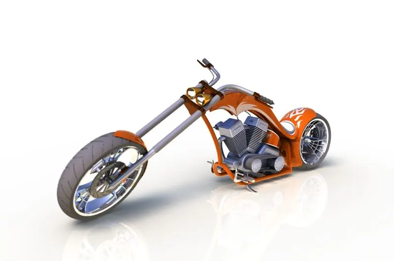
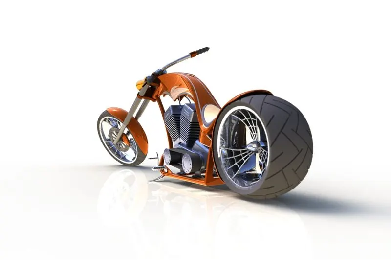
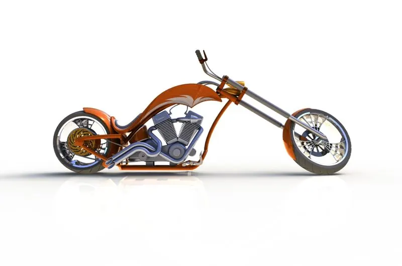
- I have attached three views of the chopper rendered for this project.
IMAGES OF ASSEMBLY MODEL
| VIEW | FRONT VIEW | SIDE VIEW | ISOMETRIC VIEW | CAMERA SETUP VIEW | TOP VIEW |
|
ASSEMBLY IMAGES |
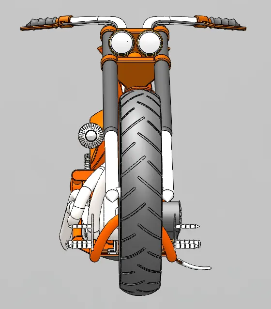 |
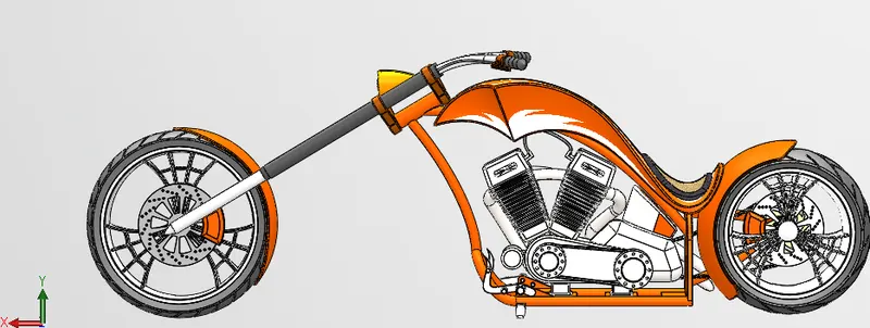 |
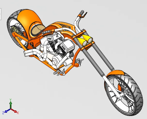 |
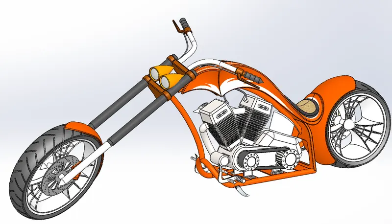 |
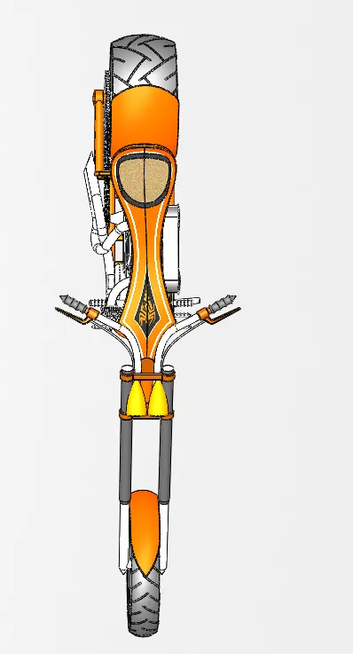 |
RENDERED IMAGES OF ASSEMBLY
| VIEW | VIEW - I | VIEW - II | VIEW - III |
|
ASSEMBLY IMAGES |
 |
 |
 |
RENDERED IMAGES OF INDIVIDUAL PARTS
| NAME OF PARTS | CHASSIS | Engine | Front Fork Suspension | REAR-WHEEL |
| IMAGES | 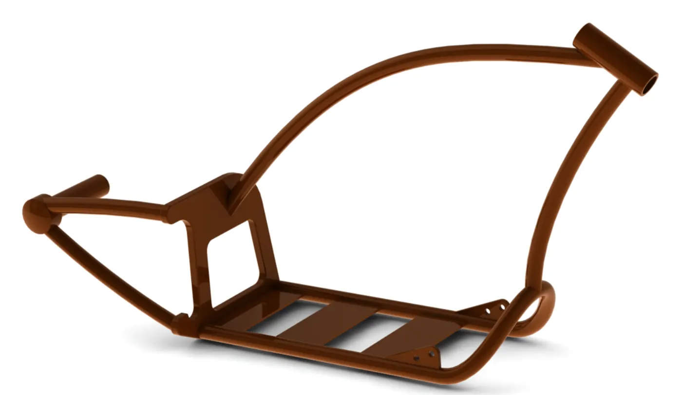 |
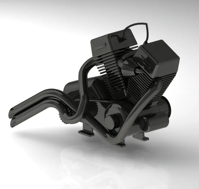 |
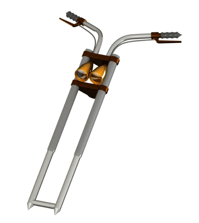 |
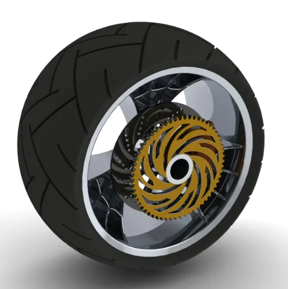 |
CONCLUSION:
Finally, a good-looking and complete chopper is designed, assembled, and rendered using the Solidworks tool.