Advanced Sheet Metal Design Using NX Cad Challenge_2_Box Assembly
BOX ASSEMBLY
Objective
To design a box assembly in NX12 using sheet metal application and its features.
Introduction
The box assembly designed is usually used for garbage collections or electronic devices and so on.
Box assembly is designed with many features like bead, simple, flange, close loop to provide more strength in-wall region.
Design Methodology
Commands/features are used as mentioned below
- Tab/Sketch - Rectangle
- Flange - Material Inside/Outside
- Closed corner
- Hem Flange - Open/ Close
- Mirror Body/ Feature
- Dimple - Sketch
- Bead - Sketch
- Datum Plane - Sketch
- Break corner
- Normal Cutout/Sketch - Rectangle
- Rebend/Unbend
- Unite
DESCRIPTION
Some of the features used here are explained below
Hem Loop - Open: It's used to bend and have the strength to the flanges structures.
Bead - Used on the bottom face of this model gives a grip feature of the box and avoid slipping while moving or placing over the surface.
Dimple - Used on the wall of the box gives rigidity and maintains its strength on normal load application to box assembly.
MODEL IMAGES
| FRONT VIEW | SIDE VIEW | ISOMETRIC VIEW | TOP VIEW | |
| BOX ASSEMBLY PICTURE | 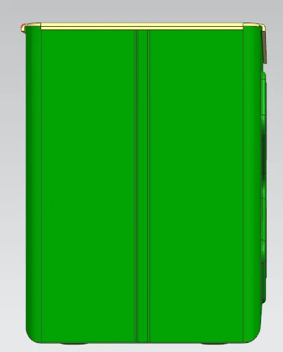 |
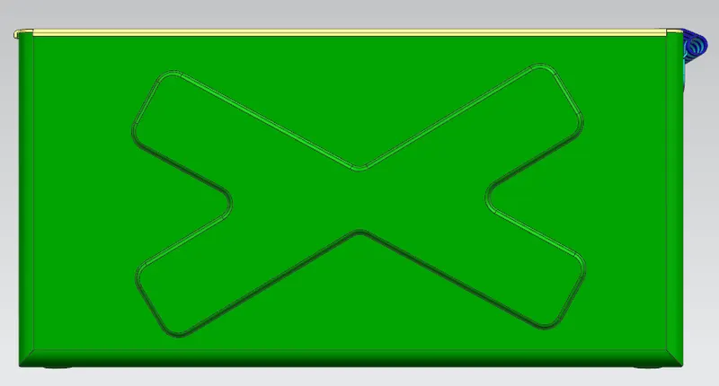 |
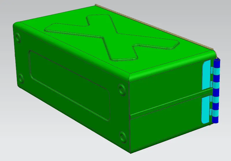 |
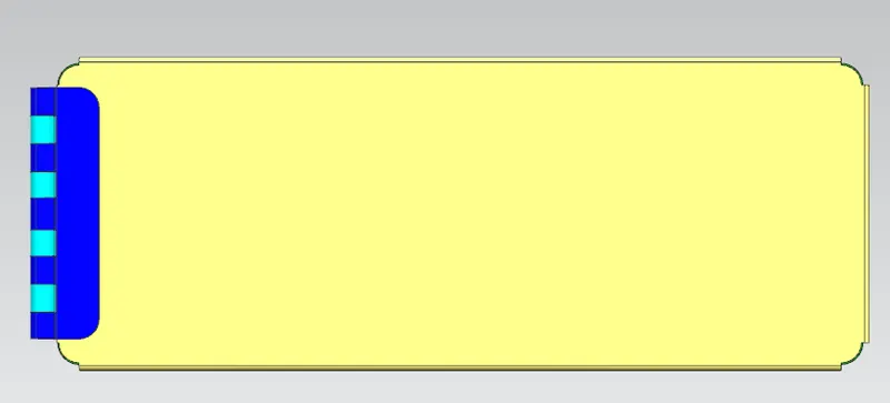 |
CONCLUSION
Box Assembly is modeled and design with various features and commands existing in the NX12 Sheet application.