Modeling & Rendering of an American chopper Bike
MODELING AND REBDERING OF AMERICAN CHOPPER USING SOLIDWORKS
OBJECTIVE:
- The main objective of this project is to model different parts of a custom designed American chopper using SOLIDWORKS.
- To assemble the different parts modeled for the American chopper.
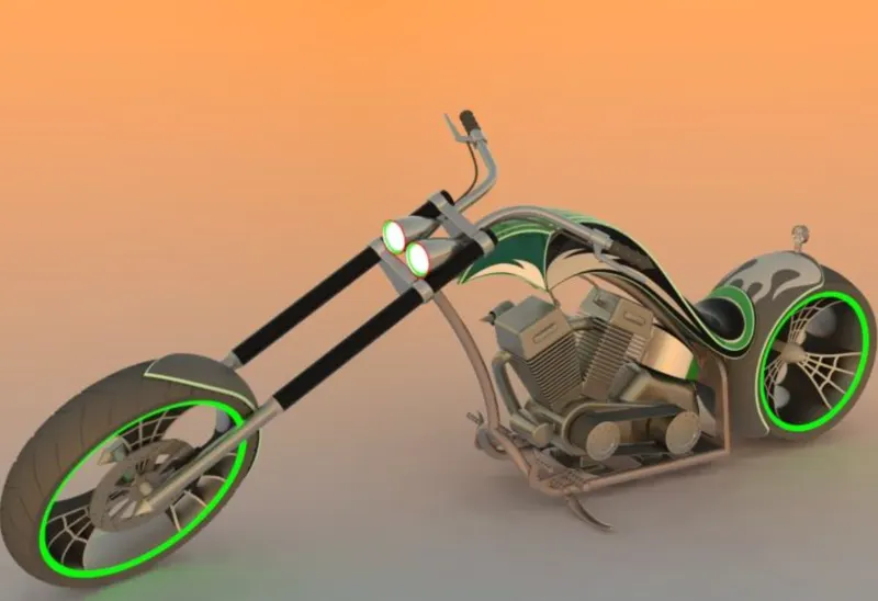
- To create a photo-realistic view of american chopper by rendering the model using solidworks photo view 360 and solid works Visualize.
PART MODELING
- Modeling in general means to create a virtual prototype of an item. it can be used for various purposes. consider an engine of a car. It has hundreds of parts. Each part can be assembled together to get the engine's final form. This type of modeling is called part modeling.
FEATURES DESCRIPTION:
SKETCH:
- Sketch is the two dimensional representation of the model with respect to plane/view from the outside of the model. In solidworks there are different sketch option available to create sketch.These are available known as Entities in solidworks. The following are the entities available in solid works Line ,arc and splines.
OFFSET:
- One or more sketch entites,selected model edges, or model faces by a specified distance. For example, you can offset entities such as spline or arcs, sets of model edges, loops, and so on. you can offset finite lines, arcs, and splines.
EXTRUDE BOSS/BASS:
- Extrude is a type of feature available in solid works to convert a 2d sketch into 3d model.
FILLET
- Fillet/Round creates a rounded internal or external face on the part. You can fillet all edges of a face, selected set of faces, selected edges or edge loops.
LOFTED BOSS/BASS:
- The loft feature allows you generates complex geometry in a single feature.It does this by interpolating surfaces between various cross-sections of the model. These cross-section can be sketches, faces, or edges. In the loft interface , these cross-section are considered "Loft profile".
DOME:
- Select one or more planar or non-planar faces. You can apply domes to faces whose centroid lies outside the face. This allows you to apply domes to irregulaly shaped contours.
EXTRUDE CUT:
- Extrude cut is another cool feature which helps to remove matreials from 3d model. it is just the opposite to extrude boss/base feature , because it cut in both direction and mainly useds for creating holes, channels, slots etc.
SPLIT
- The split tool is used to project an entity (sketch, solid, surface, face ,plane or surface spline) onto other surface or curved/planar faces. You are also able to split faces on multiple bodies with one command.
TRIM ENTITIES:
- Select the trim type based on the entites you want to trim or extend. All trim type are available with 2d sketches on 3d planes. You can use any of the following trim option:power trim.
REVOLVE:
- To create a revolve feature: create a sketch that contain one or more profiles and a centreline , line or edge to use as the axis around which the feature revolve. Click one of the following revolve tools.
DYNAMIC MIRROR:
- AN appearance defines the visual properties of the model, including color and texture. As you sketch the entities, they are mirrored about the pre-sketched sketch entity.
APPEARANCE:
- An appearance defines the visual properties of the model, including color and texture. Appearance do not affaect physical properties, which are defined by materials. Every materialis assigned a default appearance that emulates the look of the material.
COMBINE:
- Combine is the type of feature available in solidworks to manually combine two bodies.
SHELL:
- The shell defination property manager is used to define the thickness of thin and thick shell elements.
CHAMFER:
- A cut on the edge or crner of the something that makes it slope slight rather than being perfectly square.
CIRCULAR PATTERN:
- The circular parent bodies/feature are used to create a different number of instances required to create the pattern linearly.
LINEAR PATTERN:
- The linear parent bodies/features are used to create a different number of instance required to create the pattern linearly.
SURFACE MODELING:
- Surface modeling gives you the ability to build out a visual representation of an object's exterior and its contours. In other words, it's a surface.
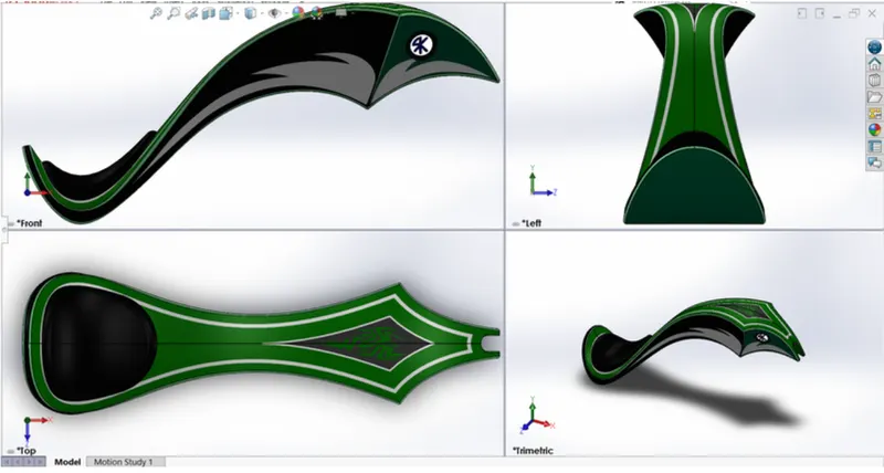
- Parts like seat, fuel tank of classic 350 are surface modeled.
FEATURES DESCRIPTION:
LOFTED SURFACE:
- Loft surfaces are surfaces generated by multiple 3D curves or exiting edges creating a smooth tangency between the selected curves.
SWEPT SURFACES:
- Sweep surfaces are surfaces that are generated from a section curve positioned along a path.
FILLED SURFACE:
- The filled surface feature constructs a surface patch with any number of sides, within a boundry defined by existing model edges, sketches, or curves,including composite curves.
SURFACE TRIM:
- Primarily used to cut away material from a surface, and provides two modes: Standard and Mutual.
EXTENDED SURFACE:
- Extended surface is used to extend the surface which is already created. Thereare different options available on the exrended surfaces. We can extend the surface tangent to the surface.
SURFACE KNIT:
- Surface knirt is used to knit the two free edges/open edges of the surface together. Also it reduces the gap between the two edges of the surface.
PARTS MODELED FOR AMERICAN CHOPPER:
- The following part of the American chopper are model in solid work and assemble together .
- Transmission belt
- Kick stand
- Front fender
- Rear fender
- Chain
- Oil tank
- pedal
- Front wheel
- Rear wheel
- Front fork
- Chassis
- Engine
- Gastank
DESCRIPTION OF THE PARTS AND FEATURE USED:
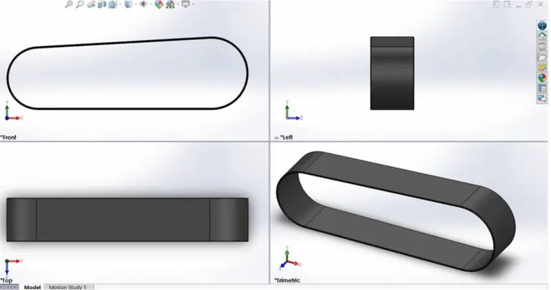
- TRANSMISSION BELT
It is the loop of flexible material used to link to or more rotating shafts mechanically ,most often parllel .Belt may be used as source of motion , to transmit power efficiently or to track relative movement .
FEATURES USED:
- Boss Extrude
- fillet
2. KICKSTAND:
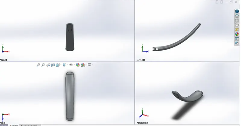
A kickstand is a device on a motercycle that allows the bike to be kept upright without leaning against another object or the aid of a person. A kickstand is usually a piece of a metel that flips down from the frame and makes contact with the ground. It is generally locoted in the middle of the bike or towards the rear.
FEATURES USED:
- Loft
- Dome
- Cut Extrude
- Split
- Boss Extrude
- Filet
3. FRONT FENDER:
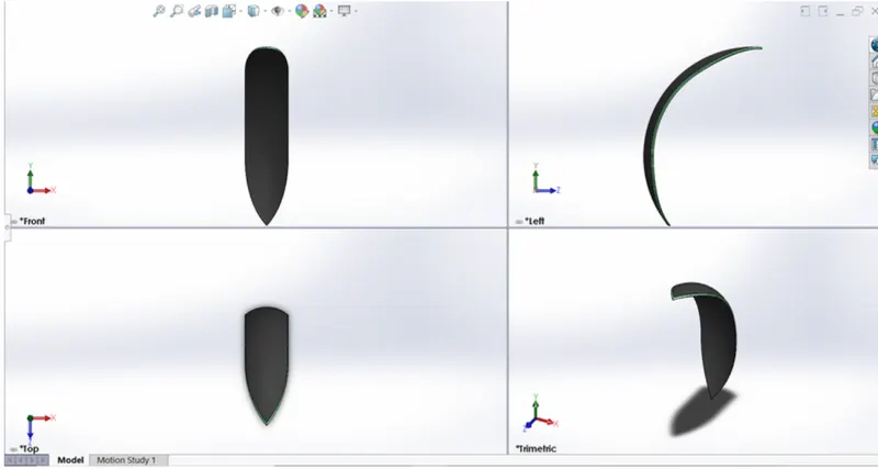
Fender is the American english term for the part of an automobile, motorcycle or other vehicle body that frames a wheel well ( the fender underside). Its primary purpose is to prevent sand , mud, rocks, liquids , and other road spray from being thrown into the air by the rotating tire.
FEATHER USED:
- Revolved boss
- Split
- Fillet
4. REAR FENDER:
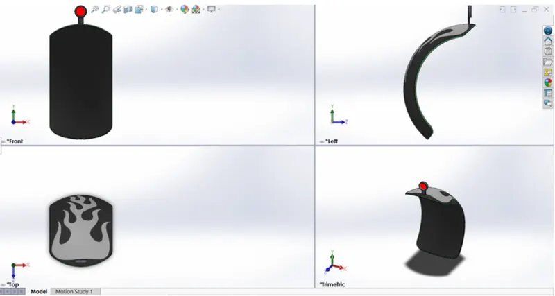
Fender is the american english term for the part of an automobile , motercycle or other vehicle body that frames a wheel well (the fender underside). Its primary purpose is to prevent sand , mud, rocks ,liquid and other road spray from being thrown into the air by the rotating tire.
FEATHER USED:
- Revolve Boss
- Split
- Filet
- Shell
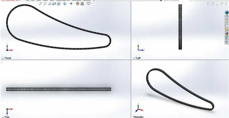
5. CHAIN:
The chain on the bike, is responsible for transferring the mechanical power from the engine to the rear wheel of the bike.
FEATURES USED:
- Extrude Boss
- Fillet
- Projected curves
- Curve pattern
- Mirror
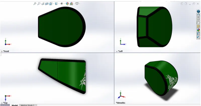
6. OIL TANK:
A oil tank has the purpose of storing lube oil to lubricate the engine parts to avoid wear and tear due to extreme heat.
FEATURES USED:
- Extrude Boss
- Filet
- Shell
- Combine
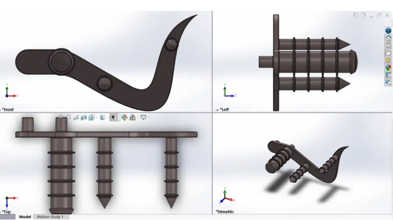
7. PEDAL:
A pedal has the function of shifting the gears the gears to get the desired the speed from the engine and also apply the breaking force.
FEATURES USED:
- Extrude Boss
- Fillet
- Revolved Boss
- Dome
- Chamfer
- Linear pattern
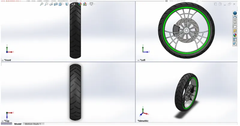
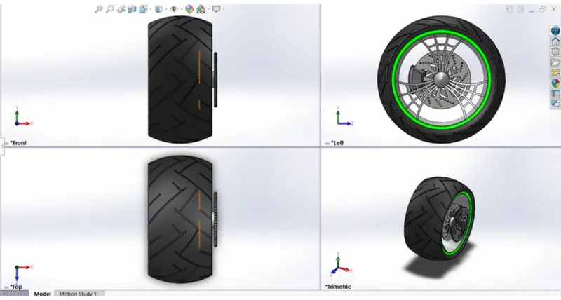
8. FRONT WHEEL
A wheel is a circular block of a hard and durable material where the center has been bored with a circular hole through an axle bearing about which the wheel rotates.
FEATURES USED:
- Extruded boss
- Cut Extrude
- Revolved cut
- Circular pattern
- Combine
- Fillet
- Chamfer
9. REAR WHEEL:
A wheel is a circular block of a hard and durable material where the center has been bored with a circular hole through an axle bearing about which the wheel rotates.
FEATURES USED:
- Extrude Boss
- Cut Extrude
- Revolved cut
- Circular Pattern
- Combine
- Fillet
- Chamfer
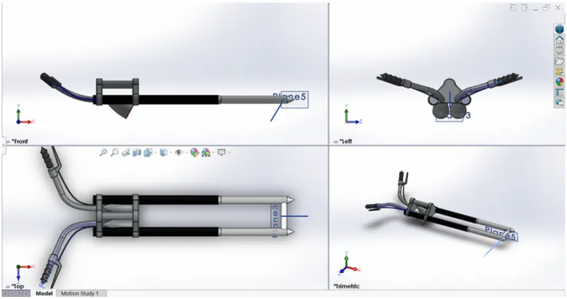
10. FRONT FORK:
A bicycle fork is the part of a bike that holds the front wheel. A fork typically consists of two blades which are joined at the top by a fork crown.
FEATURES USED:
- Extrude boss
- Revolved boss
- Fillet
- Extrude cut
- Dome
- Revove cut
- Swept boss
- Projected curve
- Mirror
- Combine
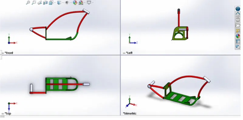
11. CHASSIS
The chassis mostly consists of hollow tube which serves as a skeleton for the gearbox, engine and front fork and rear wheel of a bike to be mounted.
FEATURES USED:
- Swept boss
- Projected curve
- Mirror
- Extrude boss
- Filet
- Extrude cut
- Dome
- Combine
- Chamfer
- Split
- Revolved boss
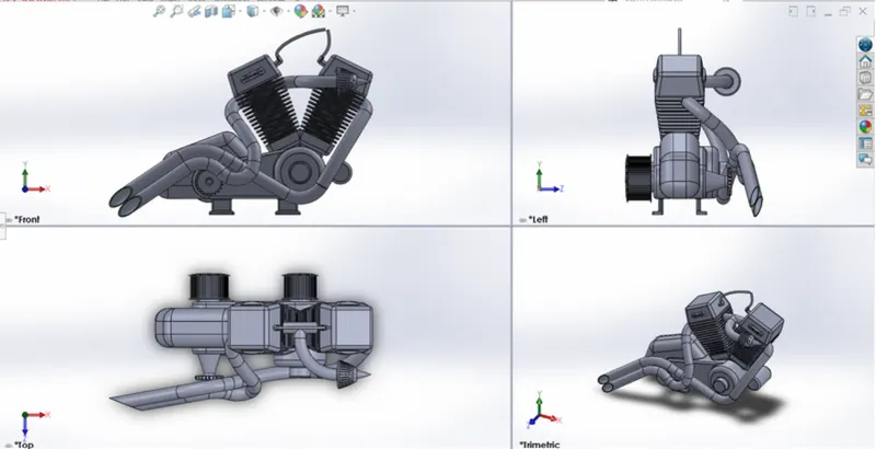
12. ENGINE:
An engine or moter is a machine designed to convert one form of energy into mechanical energy. Heat engines,like the internal combustion engine , burn a fuel to create heat which is then used to do work.
FEATURES USED:
- Swept boss
- Projected curve
- Mirror
- Extruded boss
- Filet
- Extruded cut
- Dome
- Chamfer
- Split
- Revolved boss
- Filet
- Extruded cut
- Dome
- Chamfer
- Split
- Revolved boss
- Linear pattern
- Circular pattern
- Composite curve
13. GAS TANK:
A gas tank(or petrol tank) is a safe container for flammable fluids. Though any storage tank for fuel may be so called the term is typically applied to part of an engine system in which the fuel is stored and propelled (fuel pump) or released (pressurized gas) into an engine.
FEATURES USED
- Surface loft
- Surface knit
- Project curve
- Fillet
- Swept surface
- Split
- Mirror
- Swept cut
- Plane
ASSEMBLY OF AMERICAN CHOPPER:
MAIN ASSEMBLY:
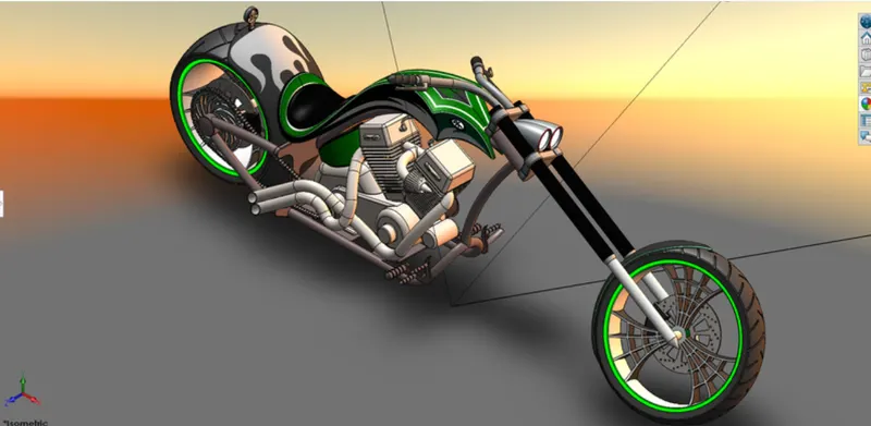
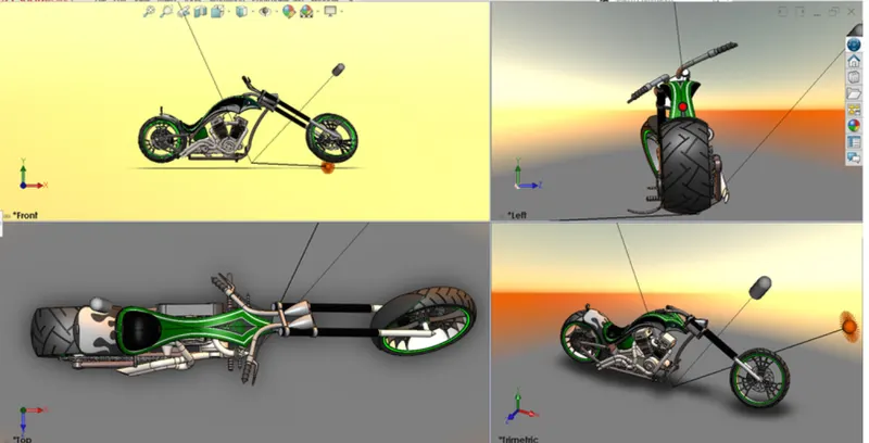
- Initially, the Chassis part is inserted in the assembly by using insert parts in the option. After that the part is inserted in the assembly environment and clicked ok to fix the chassis.
- After that the other parts of the chopper are inserted into the assembly and given possible mate conditions.
FEATURES USED TO ASSEMBLE AMERICAN CHOPPER:
- Mates
- Insert part
Mates
Mates create geometric relationships between assembly components. As we add mates, we define the allowable directions of linear or rotational motion of the components. We can move a component within its degrees of freedom, visualizing the assembly's behavior.
INSERT PARTS
We can insert the other components which need to be mated with the prime fixed component.
RENDERING:
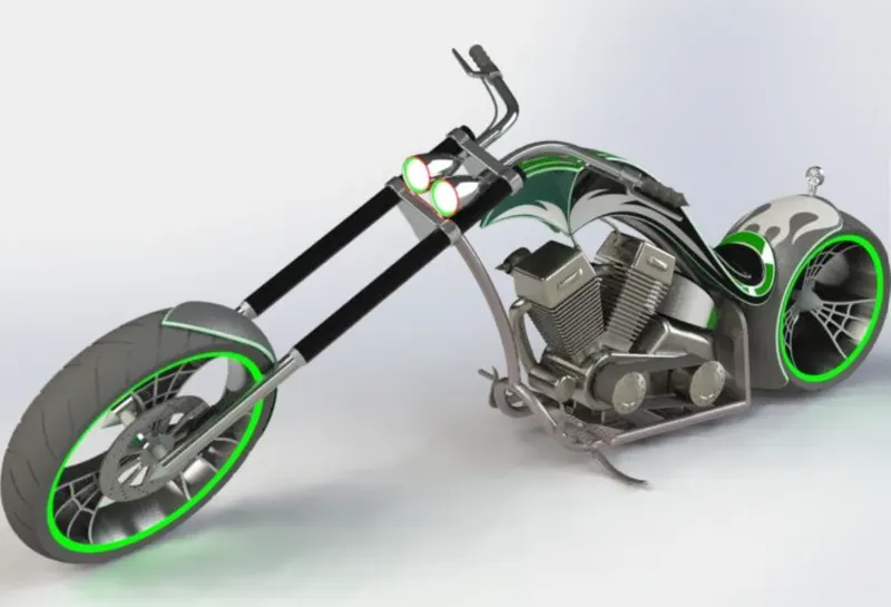
- Rendering is the process of creating realistic images of the photorealistic model with the environment.
- Rendering has been done in two ways in solid works. The following are the two ways,
- Photo views 360
- Solid-works visualize
3.In the photo-realistic model some of the mate conditions and positions are changed to render realistic models.
4.Then the photo-realistic model is rendered into realistic images with different views.
5.Here I have used both the photo-view 360 and Visualise for rendering the assembled model.
CONCLUSION:
1.The parts of the American Chopper are modeled.
2.The parts are inserted into the assembly environment and American Chopper is assembled.
3.The photo-realistic image was rendered with the use of the Photo-view 360 and Solidworks Visualise.
4.I would like to thank my mentor Mr. Soundar Rajan for helping me with the challenges I faced while modelling this beautiful beast.
5.I also attempted for CSWA examination after making this model and succesfully cleared it, thanks to the proficiency gained in this software while making this model.